Carrying manipulator for rock-soil drill rod production
Technical Field
The application relates to a drilling rod production and processing technology, in particular to a carrying manipulator for rock-soil drilling rod production.
Background
The drilling rod is one of necessary components when carrying out the probing operation in geotechnical engineering, and the drilling rod needs the vanning to handle after the workshop processing is accomplished, because drilling rod weight is great, needs two people to lift the both ends of drilling rod and put it into the transport case, not only causes workman intensity of labour big, and the operating efficiency is low, also has great potential safety hazard in addition.
Disclosure of Invention
In order to overcome above technical defect, the application provides a ground drilling rod production is with transport manipulator.
According to this application, a ground drilling rod production is with transport manipulator, the on-line screen storage device comprises a base, be equipped with the stand on the base, the upper end of stand is equipped with can the pivoted davit, be equipped with the removal frame that can lateral shifting on the davit, the lower extreme of removing the frame is equipped with the spliced pole, the lower extreme of spliced pole is rotated and is equipped with the mounting bracket, be equipped with first cylinder on the mounting bracket, the bottom of first cylinder piston rod is equipped with the lifter plate, the bottom of lifter plate is equipped with vertical arm, the lower extreme of vertical arm is equipped with horizontal arm, the one end that vertical arm was kept away from to horizontal arm is equipped with the installation arm, the lower extreme of installation arm is equipped with the removal arm that two distances can be adjusted, the lower extreme of removal arm is equipped with clamping mechanism.
Further, clamping mechanism includes the fixed upper fixed plate with the carriage boom bottom, four angles in upper fixed plate bottom all are equipped with the connecting rod, the lower extreme of connecting rod is equipped with the bottom plate, the below both ends of bottom plate all are equipped with two sets of guide holders, the lower extreme of guide holder slides and is equipped with the dead lever, the lower extreme of dead lever is equipped with presss from both sides tight arm, the inboard that presss from both sides tight arm is equipped with the clamp plate, form the clamping part between the clamp plate of the same group, the below of bottom plate is equipped with the adjusting part that can adjust two sets of clamping parts sizes simultaneously.
Further, the adjusting part is including setting up the lifing beam in bottom plate below, and the tip that is equipped with second cylinder and second cylinder piston rod on the bottom plate is fixed with the lifing beam upper end, and the both ends of lifing beam all are equipped with U type spare, and the both sides of U type spare all articulate the connecting rod that has two parallels, and the one end that U type spare was kept away from to homonymy connecting rod is articulated as an organic whole with the tight arm of clamp of homonymy.
Further, the installation arm is hollow structure, is equipped with two division boards in the installation arm, and two division boards divide into first installation cavity, drive chamber and second installation cavity with the installation arm inner chamber, rotate between two division boards and be equipped with the lead screw, and the both ends of lead screw rotate with installation arm inner chamber both ends respectively and be connected, are equipped with two screw thread portions that are located first installation cavity and second installation cavity respectively on the lead screw thread portion screw thread opposite direction, two removal arms threaded connection respectively on two screw thread portions, the upper end of first installation cavity and second installation cavity all is equipped with first guide rail, the upper end of removal arm be equipped with first slider with first guide rail sliding connection, and the lower extreme of installation arm is equipped with the bar hole that is used for the removal arm to pass.
Furthermore, be equipped with the first driven gear who is located the drive intracavity on the lead screw, horizontal arm is hollow structure and switches on each other between horizontal arm and the installation arm, and horizontal arm inner chamber rotates and is equipped with the drive shaft, and the outer end of drive shaft is equipped with changes the handle, is equipped with first drive gear on the drive shaft, is connected through the chain between first drive gear and the first driven gear.
Furthermore, the lower end of the suspension arm is provided with a vertical arm, the lower end of the vertical arm is provided with a motor base, the motor base is provided with a driving motor, an output shaft of the driving motor is provided with a second driving gear, and the stand is provided with a second driven gear meshed with the second driving gear.
Furthermore, two second guide rails are arranged on the suspension arm, a second sliding block in sliding fit with the second guide rails is arranged at the bottom of the moving frame, a transverse rack is arranged between the two second guide rails, a walking motor is arranged on the moving frame, and a power gear meshed with the transverse rack is arranged on an output shaft of the walking motor.
Furthermore, the front end of the mounting rack is provided with two guide strips, guide sleeve rods are slidably arranged on the guide strips, and the lower ends of the guide sleeve rods are fixedly connected with the lifting plate.
Furthermore, a handle is arranged at the bottom of the rear end of the mounting frame, and a remote controller is arranged on the handle.
The utility model provides a ground is transport manipulator for drilling rod production can press from both sides clamping mechanism to suitable direction through hand handle and can press from both sides in proper order a plurality of drilling rods and get and transfer to the transportation wooden case in, and convenient nimble has effectively alleviateed intensity of labour, and presss from both sides the stability that the mechanism every group all set up two clamping parts and guarantee to press from both sides, and the security is higher, can adjust the distance between two sets of clamping mechanism according to the length of drilling rod is nimble simultaneously, and the suitability is wider.
Drawings
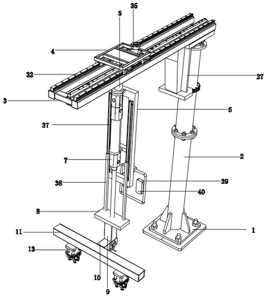
Fig. 1 is a schematic structural view of a handling robot for producing an earth boring bar according to an embodiment of the present application.
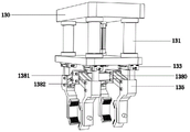
Fig. 2 is a schematic structural diagram of a clamping mechanism in a handling manipulator for producing geotechnical drill rods according to an embodiment of the application.
Fig. 3 is a schematic side view of a clamping mechanism in a handling manipulator for producing geotechnical drill rods according to an embodiment of the application.
Fig. 4 is a schematic view illustrating a bottom structure of a mounting arm in a handling robot for producing geotechnical drill rods according to an embodiment of the present application.
Fig. 5 is a schematic view illustrating an internal structure of a mounting arm in a handling robot for producing geotechnical drill rods according to an embodiment of the present application.
Fig. 6 is a schematic structural diagram of a boom and a stand column in a carrying manipulator for rock-soil drill rod production according to an embodiment of the application.
Fig. 7 is a schematic view illustrating a transmission structure of a movable frame in a handling robot for producing geotechnical drill rods according to an embodiment of the present application.
Reference numerals: 1. a base, 2, a column, 3, a boom, 4, a moving frame, 5, a connecting column, 6, a mounting frame, 7, a first cylinder, 8, a lifting plate, 9, a longitudinal arm, 10, a transverse arm, 11, a mounting arm, 12, a moving arm, 13, a clamping mechanism, 130, an upper fixing plate, 131, a connecting rod, 132, a lower fixing plate, 133, a guide holder, 134, a fixing rod, 135, a clamping arm, 136, a clamping plate, 137, a clamping part, 138, an adjusting component, 1380, a lifting beam, 1381, a U-shaped piece, 1382, a connecting rod, 14, a second cylinder, 15, a partition plate, 16, a first mounting cavity, 17, a driving cavity, 18, a second mounting cavity, 19, a lead screw, 20, a threaded part, 21, a first guide rail, 22, a first slider, 23, a strip-shaped hole, 24, a first driven gear, 25, a driving shaft, 26, a first driving gear, 27, a vertical arm, 28, a motor holder, 29, a driving motor, 30. the device comprises a second driving gear 31, a second driven gear 32, a second guide rail 33, a second sliding block 34, a transverse rack 35, a walking motor 36, a power gear 37, a guide bar 38, a guide sleeve rod 39, a handle 40, a remote controller 41 and a rotating handle.
Detailed Description
The technical solutions in the embodiments of the present application will be clearly and completely described below with reference to the drawings in the embodiments of the present application, and it is obvious that the described embodiments are only a part of the embodiments of the present application, and not all of the embodiments. All other embodiments, which can be derived by a person skilled in the art from the embodiments given herein without making any creative effort, shall fall within the protection scope of the present application.
As shown in the accompanying drawing 1, a carrying manipulator for rock-soil drill rod production, including a base 1, be equipped with stand 2 on the base 1, the upper end of stand 2 is equipped with can pivoted davit 3, be equipped with the removal frame 4 that can lateral shifting on the davit 3, the lower extreme of removal frame 4 is equipped with spliced pole 5, the lower extreme of spliced pole 5 rotates and is equipped with mounting bracket 6, be equipped with first cylinder 7 on the mounting bracket 6, the bottom of first cylinder 7 piston rod is equipped with lifter plate 8, the bottom of lifter plate 8 is equipped with vertical arm 9, the lower extreme of vertical arm 9 is equipped with horizontal arm 10, the one end that horizontal arm 10 kept away from vertical arm 9 is equipped with installation arm 11, the lower extreme of installation arm 11 is equipped with two removal arms 12 that can adjust apart from, the lower extreme of removal arm 12 is equipped with clamping mechanism 13.
In one embodiment, as shown in fig. 2, the clamping mechanism 13 includes an upper fixing plate 130 fixed to the bottom of the moving arm 12, four corners of the bottom of the upper fixing plate 130 are provided with connecting rods 131, a lower fixing plate 132 is provided at the lower end of the connecting rods 131, two sets of guide seats 133 are provided at both lower ends of the lower fixing plate 132, a fixing rod 134 is slidably provided at the lower end of the guide seat 133, a clamping arm 135 is provided at the lower end of the fixing rod 134, a clamping plate 136 is provided at the inner side of the clamping arm 135, a non-slip mat is provided at the inner side of the clamping plate 136, a clamping portion 137 is formed between the clamping plates 136 of the same set, and an adjusting assembly 138 capable of adjusting the sizes of the two sets of clamping portions 137 is provided below the lower fixing plate 132.
In one embodiment, as shown in fig. 3, the adjusting assembly 138 includes a lifting beam 1380 disposed below the lower fixing plate 132, the lower fixing plate 132 is provided with a second cylinder 14, the end of the piston rod of the second cylinder 14 is fixed to the upper end of the lifting beam 1380, both ends of the lifting beam 1380 are provided with a U-shaped member 1381, both sides of the U-shaped member 1381 are hinged to two parallel connecting rods 1382, one end of the connecting rod 1382 away from the U-shaped member 1381 on the same side is hinged to the clamping arm 135 on the same side, the second cylinder 14 is actuated, the piston rod of the second cylinder 14 is retracted, the retraction of the second cylinder 14 drives the lifting beam 1380 to ascend, the lifting beam 1380 simultaneously drives the U-shaped members 1381 on both ends to ascend, and the fixing rod 134 is slidably disposed in the guide seat 133, so that when the U-shaped member 1381 ascends, the connecting rod 1382 can drive the two clamping arms 135 of the same group to approach each other, and the clamping plates 136 of the same group approach each other, the reduced clamping portion 137 can clamp drill rods of different thicknesses.
In one embodiment, as shown in fig. 4-5, in order to clamp drill rods with different lengths, the mounting arm 11 is a hollow structure, two partition plates 15 are arranged in the mounting arm 11, the inner cavity of the mounting arm 11 is divided into a first mounting cavity 16, a driving cavity 17 and a second mounting cavity 18 by the two partition plates 15, a lead screw 19 is rotatably arranged between the two partition plates 15, two ends of the lead screw 19 are respectively rotatably connected with two ends of the inner cavity of the mounting arm 11, two threaded portions 20 respectively located in the first mounting cavity 16 and the second mounting cavity 18 are arranged on the lead screw 19, the thread directions of the two threaded portions 20 are opposite, the two moving arms 12 are respectively and threadedly connected to the two threaded portions 20, a first guide rail 21 is arranged at the upper end of each of the first mounting cavity 16 and the second mounting cavity 18, a first slider 22 slidably connected with the first guide rail 21 is arranged at the upper end of the moving arm 12, and the lower end of the mounting arm 11 is provided with a strip-shaped hole 23 for the moving arm 12 to pass through, and since the thread directions of the two thread portions 20 are opposite, the rotation of the screw rod 19 can drive the two moving arms 12 to approach each other or move away from each other, wherein the mutual matching of the first guide rail 21 and the first slider 22 can stabilize the moving direction of the moving arm 12.
In one embodiment, in order to conveniently and manually adjust the distance between the two moving arms 12, the screw rod 19 is provided with a first driven gear 24 located in the driving cavity 17, the transverse arm 10 is of a hollow structure, the transverse arm 10 and the mounting arm 11 are communicated with each other, the inner cavity of the transverse arm 10 is rotatably provided with a driving shaft 25, the outer end of the driving shaft 25 is provided with a rotating handle 41, the driving shaft 25 is provided with a first driving gear 26, the first driving gear 26 is connected with the first driven gear 24 through a chain, the rotating handle 41 is rotated to drive the driving shaft 25 to rotate, the driving shaft 25 can drive the first driving gear 26 to rotate, and the first driving gear 26 drives the first driven gear 24 to rotate through the chain, so that the rotation of the screw rod 19 can be driven.
In one embodiment, as shown in fig. 6, the lower end of the boom 3 is provided with an upright arm 27, the lower end of the upright arm 27 is provided with a motor base 28, the motor base 28 is provided with a driving motor 29, an output shaft of the driving motor 29 is provided with a second driving gear 30, the upright column 2 is provided with a second driven gear 31 engaged with the second driving gear 30, the driving motor 29 is started, the driving motor 29 drives the second driving gear 30 to rotate, the second driving gear 30 can drive the boom 3 to rotate in cooperation with the second driven gear 31, and the rotation of the boom 3 can adjust the clamping mechanism 13 at the lower end of the movable arm 12 to a proper position, so as to place the clamped drill rod in a designated transport box.
In one embodiment, as shown in fig. 7, in order to further adjust the transverse position of the clamping drill rod, two second guide rails 32 are provided on the boom 3, a second slider 33 slidably engaged with the second guide rails 32 is provided at the bottom of the movable frame 4, a transverse rack 34 is provided between the two second guide rails 32, a traveling motor 35 is provided on the movable frame 4, an output shaft of the traveling motor 35 is provided with a power gear 36 engaged with the transverse rack 34, the traveling motor 35 is started, the traveling motor 35 drives the power gear 36 to rotate, and the power gear 36 cooperates with the transverse rack 34 to drive the movable frame 4 to move transversely.
Two guide strips 37 are arranged at the front end of the mounting frame 6, guide sleeve rods 38 are arranged on the guide strips 37 in a sliding mode, and the lower ends of the guide sleeve rods 38 are fixedly connected with the lifting plate 8.
The bottom of the rear end of the mounting frame 6 is provided with a handle 39, the handle 39 is provided with a remote controller 40, and the remote controller 40 is provided with buttons for controlling the operation of the first cylinder 7, the second cylinder 14, the driving motor 29 and the walking motor 35.
The working principle is as follows: the base 1 is fixed at a designated position through a fixing screw, when a drill rod in a workshop needs to be boxed, a worker holds the handle 39 by hand, the clamping mechanism 13 at the lower end of the moving arm 12 is adjusted to a proper position through a corresponding knob on the remote controller 40, when the drill rod needs to be clamped, the first air cylinder 7 is started, a piston rod of the first air cylinder 7 extends to drive the lifting plate 8 to descend, and the descending of the lifting plate 8 drives the clamping mechanism 13 at the lower end of the moving arm 12 to descend to a proper position; the rotating handle 41 is rotated manually, the rotating handle 41 drives the driving shaft 25 to rotate, the driving shaft 25 can drive the first driving gear 26 to rotate, the first driving gear 26 drives the first driven gear 24 to rotate through a chain, so that the screw rod 19 can be driven to rotate, the rotation of the screw rod 19 can drive the two moving arms 12 to approach or separate from each other due to the opposite thread directions of the two thread parts 20, when the two clamping mechanisms 13 at the lower end of the moving arm 12 are adjusted to proper positions, the second air cylinder 14 is started, the piston rod of the second air cylinder 14 is contracted, the second air cylinder 14 is contracted to drive the lifting beam 1380 to ascend, the lifting beam 1380 can simultaneously drive the U-shaped parts 1381 at the two ends to ascend, and the fixing rod 134 is arranged in the guide seat 133 in a sliding manner, so when the U-shaped parts 1381 ascend, the two clamping arms 135 in the same group can be driven to approach each other under the action of the connecting rod 1382, at the same time, the same group of clamping plates 136 are also close to each other, and the reduced clamping parts 137 can clamp drill rods with different thicknesses; and starting the first air cylinder 7 again, wherein the piston rod of the first air cylinder 7 is shortened to lift the drill rod to a certain height, so that the drill rod can be lifted to a proper height, and the drill rod can be placed in a designated transport box by starting the driving motor 29 to drive the suspension arm 3 to rotate and rotating the mounting frame 6.
The above embodiments are only used for illustrating the technical solutions of the embodiments of the present application, and are not limited thereto; although the embodiments of the present application have been described in detail with reference to the foregoing embodiments, those skilled in the art will understand that: the technical solutions described in the foregoing embodiments may still be modified, or some technical features may be equivalently replaced; and such modifications or substitutions do not depart from the spirit and scope of the corresponding technical solutions, which are defined by the claims of this application.