Disclosure of Invention
The invention aims to: in order to solve the problem that dust cannot be effectively prevented, an intelligent manufacturing production line teaching equipment platform is provided.
In order to achieve the purpose, the invention provides the following technical scheme: an intelligent manufacturing production line teaching equipment platform comprises a main body, wherein two groups of supporting columns are fixedly connected to the top ends of two sides of the main body, first dustproof cloth is arranged above two sides of the main body, second dustproof cloth is arranged above two ends of the main body, limiting sliding plates which are mutually sleeved with the supporting columns are fixedly connected to the bottom ends of the first dustproof cloth and the second dustproof cloth, and winding mechanisms which are mutually sleeved with the first dustproof cloth and the second dustproof cloth are arranged on the upper surfaces of the supporting columns; the winding mechanism comprises a motor, a top plate, first winding shafts, first bevel gears, limiting cylinders, a lifting threaded rod, second winding shafts, second bevel gears, third bevel gears, limiting baffle plates and extending slide rods, the top plate is arranged on the upper surfaces of two groups of supporting columns, the motor is arranged at the top end of one side of the top plate and is positioned right above one supporting column, the second bevel gears are arranged in two groups, the two groups of second bevel gears are respectively arranged inside two sides of the top plate and are positioned right above the supporting column, one second bevel gear is fixed at the output end of the motor, the lifting threaded rod is fixed at the bottom end of the second bevel gear and is sleeved with the supporting column, the first winding shafts are respectively arranged inside two sides of the top plate and are sleeved with first dustproof cloth, the first bevel gears are fixed at two ends of the first winding shafts and are positioned on the upper surface of one end of the second bevel gear, the second winding shafts are respectively arranged inside two ends of the top plate and are sleeved with second dustproof cloth, the third bevel gears are fixed at two sides of the second winding shafts and are positioned on the upper surfaces of the second bevel gears, the limiting baffle plates, the limiting baffles are arranged on the upper surfaces of the second winding shafts and are connected with the limiting cylinders, the limiting baffle plates, the limiting baffles are arranged on the upper surfaces of the upper ends of the third bevel gears, and are connected with the limiting cylinders; the bottom of roof just is located the upper surface of support column and is provided with dust removal mechanism for carry out the dust absorption ash removal to the surface of first dustproof cloth, second dustproof cloth.
Thus, when the dust collection mechanism is used, the starting motor drives a second bevel gear to rotate, the second bevel gear drives a lifting threaded rod to rotate, the lifting threaded rod stably ascends in the supporting column through balls, the top plate is pushed to drive a plurality of lifting threaded rods to ascend synchronously, the lifting threaded rods rotate under the driving of the top plate through balls, the second bevel gear rotates under the driving of the lifting threaded rods, the second bevel gear drives a first bevel gear and a third bevel gear respectively through meshing of toothed blocks, the first bevel gear and the third bevel gear respectively drive a first winding shaft and a second winding shaft to rotate, the first winding shaft and the second winding shaft respectively roll first dust-proof cloth and second dust-proof cloth, the first dust-proof cloth and the second dust-proof cloth respectively drive limiting sliding plates to ascend stably, the limiting sliding plates slide and are limited through the limiting cylinders, when the limiting baffle plates are in contact with the limiting plates, the limiting sliding plates drive the limiting baffle plates to stably and synchronously ascend, the limiting baffle plates drive the extending sliding rods to extend to the top end of the limiting cylinders, and the limiting plates can slide the first dust-proof cloth and the second dust collection mechanism can conveniently and dust-collection mechanism can collect dust-proof cloth through the second dust-proof cloth.
As a still further scheme of the invention: the dust removal mechanism includes fourth bevel gear, universal driving chain, first dust suction box, spacing inserted block, dust removal scraper blade, containing box, second dust suction box, reciprocal threaded rod, extraction fan, gangbar and two-way bevel gear, first dust suction box fixes the both sides bottom at the roof, the bottom at the roof both ends is fixed to the second dust suction box, the containing box sets up the upper surface at the support column, and contacts with first dust suction box, second dust suction box, spacing inserted block fixes the top at the containing box, and cup joints each other with the roof, the extraction fan is provided with two sets ofly, and is two sets of the extraction fan sets up respectively inside the both ends of first dust suction box, and is located the one end of containing box, reciprocal threaded rod fixes the one end that a set of extraction fan is close to each other, and is located the inside of first dust suction box, the dust removal scraper blade sets up inside the one end of first dust suction box, and cup joints each other with reciprocal one end of first dust removal scraper blade, and the universal driving chain sets up the one end of first bevel gear and the one end of keeping away from the linkage belt, the linkage belt is connected with the bevel gear, and the linkage bar is connected with the four bevel gear, and the linkage bar is connected with the linkage bar.
Thus, the two-way bevel gear is driven to rotate by the second bevel gear, the four bevel gear is driven to rotate by the meshing of the toothed blocks, the linkage rod is driven to rotate by the fourth bevel gear, the linkage rod drives the linkage belt to rotate, the reciprocating threaded rod drives the reciprocating threaded rod to rotate by the rotating shaft, the reciprocating threaded rod drives the air suction fan to rotate by the rotating shaft, so that the internal air of the first dust suction box and the second dust suction box can be respectively sucked into the storage box to conveniently store dust, and the first dust suction box and the second dust suction box respectively suck dust on the outer walls of the first dustproof cloth and the second dustproof cloth through the dust suction holes, so that the outer walls of the first dustproof cloth and the second dustproof cloth can be conveniently dedusted, the utility model discloses a dust removal scraper blade, including the dust removal scraper blade, the reciprocating threaded rod drives the ball through the external screw thread simultaneously and makes the dust removal scraper blade respectively to first dust suction box, the inside of second dust suction box reciprocates and scrapes the wall, thereby can effectively assist the dust and accomodate, after imparting knowledge to students through the main part, carry out the reverse operation to above-mentioned operation, thereby carry out dust cover to the top equipment of main part, thereby be convenient for reduce the contact of dust and equipment, the lower surface that the storage box breaks away from the roof is stimulateeed to the pulling simultaneously, the storage box drives spacing inserted block and breaks away from the inside of roof this moment, thereby can carry out centralized processing to the dust of collecting, then make spacing inserted block insert the inside to the roof through promoting the storage box, thereby can carry out convenient installation to the storage box, so that the dustproof protection to equipment.
As a still further scheme of the invention: the support column is provided with the lifting chute that matches rather than the removal orbit each other with spacing slide, lift threaded rod department of meeting, a set of support column, second bevel gear are including two.
So, can make spacing slide, lift threaded rod carry out spacing slip in the inside of support column through the lift spout.
As a still further scheme of the invention: the support column is provided with a lifting threaded rod, the lifting threaded rod is connected with the support column through a first bevel gear, the first bevel gear is connected with a second bevel gear, the second bevel gear is connected with the lifting threaded rod through a third bevel gear, and the second bevel gear is fixedly connected with the lifting threaded rod through a rotating shaft.
So, make lift threaded rod rotate when the inside of support column goes up and down through the ball to can drive the second bevel gear and rotate.
As a still further scheme of the invention: the output end of the motor, the first winding shaft, the second winding shaft and the top plate are rotatably connected through bearings, the outer wall of the limiting baffle is slightly larger than the outer wall of the limiting cylinder, and a moving slot matched with the moving track of the top plate is formed in the position where the top plate is connected with the limiting insertion block.
So, through the limit baffle who slightly is greater than spacing section of thick bamboo outer wall, can make limit baffle under the drive of spacing slide, drive and extend the slide bar and carry out spacing extension.
As a still further scheme of the invention: reciprocating threaded rod and air exhaust fan pass through pivot fixed connection, the linkage area cup joints each other with the pivot, the one end that the air exhaust fan is close to reciprocating threaded rod is provided with cup joints each other and with main part fixed connection's support frame with the pivot.
So, make the fan of bleeding rotate under the drive of reciprocal threaded rod through the support frame.
As a still further scheme of the invention: the dust removal scraper blade is provided with the ball rather than the external screw thread department of meeting mutually supporting with reciprocal threaded rod, the one end that the gangbar is located the gangbar area has cup jointed the backup pad with first dust absorption case fixed connection.
So, make the dust removal scraper blade under the drive of reciprocal threaded rod through the ball, carry out reciprocal scraping at first dust absorption case, second dust absorption case to its inner wall adhesive dust respectively.
As a still further scheme of the invention: the two-way bevel gear is meshed with the fourth bevel gear and the second bevel gear through the tooth blocks, the two-way bevel gear is rotationally connected with the top plate through the rotating shaft, and a plurality of dust suction holes are formed in one sides, close to the first dustproof cloth and the second dustproof cloth, of the first dust suction box and the second dust suction box.
So, can make first dust absorption case, second dust absorption case carry out the dust absorption of conveniently bleeding to the surface of first dustproof cloth, the dustproof cloth of second through a plurality of dust absorption holes.
As a still further scheme of the invention: the inside fourth bevel gear, the gangbelt, the dust removal scraper blade, reciprocating threaded rod, the fan of bleeding, gangbar, two-way bevel gear that are the same with first dust absorption case that is provided with of both sides of second dust absorption case, a set of the fan of bleeding is including two, two the flabellum of the fan of bleeding is opposite direction.
So, make two extraction fans can conveniently take out the dust of first suction box, the inside of second suction box through being opposite direction's flabellum.
Compared with the prior art, the invention has the beneficial effects that:
1. by arranging the winding mechanism, the mechanism can realize dust prevention and protection on equipment, a motor is started, and the first winding shaft and the second winding shaft respectively wind first dustproof cloth and second dustproof cloth through mutual matching of the top plate, the first bevel gear, the lifting threaded rod, the second bevel gear and the third bevel gear;
2. through setting up dust removal mechanism, this mechanism can realize the centralized processing to the dust, drive two-way bevel gear through the second bevel gear and rotate, pass through fourth bevel gear this moment, the linkage area, reciprocal threaded rod, the fan of bleeding, the mutually supporting of gangbar and two-way bevel gear, make first suction box, the second suction box is respectively to first dustproof cloth through the dust absorption hole, the outer wall dust absorption of second dustproof cloth, simultaneously through the dust removal scraper blade, the containing box, reciprocal threaded rod, mutually supporting of the fan of bleeding, can be respectively to first suction box, the inside of second suction box removes dust and accomodates, and through spacing inserted block, the dust centralized processing can be carried out to the dust of collecting to the mutually supporting of containing box, so that the dustproof protection to equipment.
Detailed Description
The technical solutions in the embodiments of the present invention will be clearly and completely described below with reference to the drawings in the embodiments of the present invention, and it is obvious that the described embodiments are only a part of the embodiments of the present invention, and not all of the embodiments. All other embodiments, which can be obtained by a person skilled in the art without making any creative effort based on the embodiments in the present invention, belong to the protection scope of the present invention.
In the description of the present invention, it should be noted that the terms "center", "upper", "lower", "left", "right", "vertical", "horizontal", "inner", "outer", etc., indicate orientations or positional relationships based on the orientations or positional relationships shown in the drawings, and are only for convenience of description and simplicity of description, but do not indicate or imply that the device or element being referred to must have a particular orientation, be constructed and operated in a particular orientation, and thus, should not be construed as limiting the present invention. Furthermore, the terms "first," "second," and "third" are used for descriptive purposes only and are not to be construed as indicating or implying relative importance. In the description of the present invention, it should be noted that, unless otherwise explicitly specified or limited, the terms "mounted," "connected," and "disposed" are to be construed broadly, e.g., as meaning either a fixed connection, a removable connection, or an integral connection; can be mechanically or electrically connected; they may be connected directly or indirectly through intervening media, or they may be interconnected between two elements. The specific meanings of the above terms in the present invention can be understood in specific cases to those skilled in the art. The following describes an embodiment of the present invention based on its overall structure.
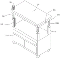
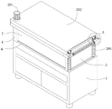
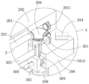
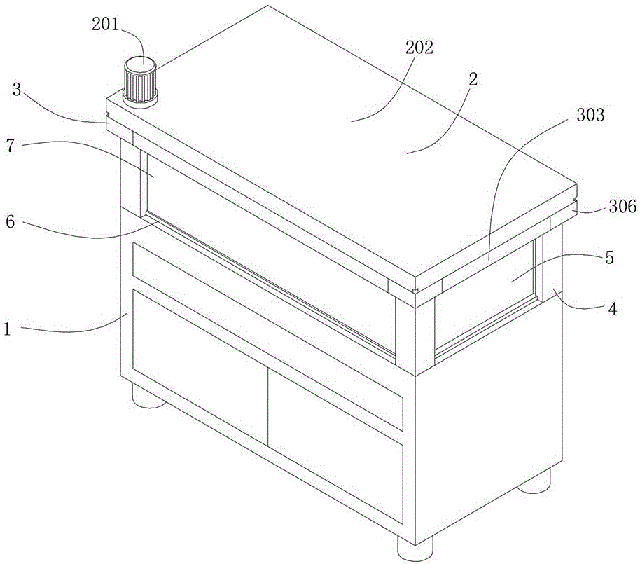
Referring to fig. 1 to 7, in the embodiment of the present invention, an intelligent manufacturing production line teaching equipment platform includes a main body 1, two sets of support columns 4 are fixedly connected to top ends of two sides of the main body 1, first dustproof cloths 5 are arranged above two sides of the main body 1, second dustproof cloths 7 are arranged above two ends of the main body 1, bottom ends of the first dustproof cloths 5 and the second dustproof cloths 7 are fixedly connected with limiting sliding plates 6 which are in sleeve joint with the support columns 4, and a winding mechanism 2 which is in sleeve joint with the first dustproof cloths 5 and the second dustproof cloths 7 is arranged on an upper surface of the support columns 4; the winding mechanism 2 comprises a motor 201, a top plate 202, a first winding shaft 203, a first bevel gear 204, a limiting cylinder 205, a lifting threaded rod 206, a second winding shaft 207, two groups of second bevel gears 208, a third bevel gear 209, a limiting baffle 2010 and an extending slide bar 2011, wherein the top plate 202 is arranged on the upper surfaces of two groups of supporting columns 4, the motor 201 is arranged at the top end of one side of the top plate 202 and is positioned right above one supporting column 4, the two groups of second bevel gears 208 are arranged, the two groups of second bevel gears 208 are respectively arranged inside two sides of the top plate 202 and are positioned right above the supporting column 4, one second bevel gear 208 is fixed at the output end of the motor 201, the lifting threaded rod 206 is fixed at the bottom end of the second bevel gear 208 and is mutually sleeved with the supporting columns 4, the first winding shaft 203 is arranged in two sides of the top plate 202, the two limiting cylinders 205 are arranged, the two limiting cylinders 205 are respectively arranged below the first bevel gear 204 and the third bevel gear 209 and are fixedly connected with the main body 1 and are mutually sleeved with the limiting sliding plate 6, the limiting baffle 2010 is arranged on the upper surface of the limiting cylinder 205, the extending slide bar 2011 is fixed at the bottom end of the limiting baffle 2010 and is mutually sleeved with the limiting cylinder 205; the bottom end of the top plate 202 and the upper surface of the support column 4 are provided with a dust removing mechanism 3 for dust collection and dust removal on the surfaces of the first dustproof cloth 5 and the second dustproof cloth 7.
In this embodiment: when the dustproof cloth winding machine is used, the motor 201 is started to drive the second bevel gear 208 to rotate, at the moment, the second bevel gear 208 drives the lifting threaded rod 206 to rotate, at the same time, the lifting threaded rod 206 stably ascends in the supporting column 4 through balls, the top plate 202 is pushed to drive the lifting threaded rods 206 to synchronously ascend, at the moment, the lifting threaded rods 206 are driven by the balls to rotate and ascend, at the same time, the second bevel gear 208 is driven by the lifting threaded rod 206 to rotate, at the moment, the second bevel gear 208 drives the first bevel gear 204 and the third bevel gear 209 to rotate through tooth meshing, at the same time, the first bevel gear 204 and the third bevel gear 209 drive the first winding shaft 203 and the second winding shaft 207 to rotate, at the moment, the first winding shaft 203 and the second winding shaft 207 respectively wind the first dustproof cloth 5 and the second dustproof cloth 7, simultaneously first dustproof cloth 5, second dustproof cloth 7 drives spacing slide 6 respectively and stably rises, spacing slide 6 slides spacingly through a spacing section of thick bamboo 205 this moment, when limit baffle 2010 contacts with spacing slide 6, limit baffle 6 drives limit baffle 2010 and stably rises in step this moment, limit baffle 2010 drives extension slide bar 2011 simultaneously and extends to the top outer wall of a spacing section of thick bamboo 205, thereby slide spacingly to limit slide 6, can realize to first dustproof cloth 5, the convenient rolling of second dustproof cloth 7, can be to first dustproof cloth 5 through dust removal mechanism 3 simultaneously, when rolling of second dustproof cloth 7, to first dustproof cloth 5, the outer wall of second dustproof cloth 7 carries out the dust absorption, thereby to first dustproof cloth 5, the outer wall of second dustproof cloth 7 carries out convenient dust removal.
As a preferred embodiment of the present invention, the dust removing mechanism 3 includes a fourth bevel gear 301, a linkage belt 302, a first dust suction box 303, a limiting insert block 304, a dust removing scraper 305, a storage box 306, a second dust suction box 307, a reciprocating threaded rod 308, suction fans 309, a linkage rod 3010, and a bidirectional bevel gear 3011, the first dust suction box 303 is fixed at the bottom end of both sides of the top plate 202, the second dust suction box 307 is fixed at the bottom end of both ends of the top plate 202, the storage box 306 is disposed on the upper surface of the supporting column 4 and is in contact with the first dust suction box 303 and the second dust suction box 307, the limiting insert block 304 is fixed at the top end of the storage box 306 and is in socket joint with the top plate 202, the suction fans 309 are provided in two sets, the suction fans 309 are respectively disposed inside both ends of the first dust suction box 303 and are located at one end of the storage box 306, the reciprocating threaded rod 308 is fixed at one end, close to each other, of the group of suction fans 309 and located inside the first dust collection box 303, the dust removal scraper blade 305 is arranged inside one end of the first dust collection box 303 and is sleeved with the reciprocating threaded rod 308, the linkage belt 302 is arranged inside one end of the first dust collection box 303 and is located at one end of the dust removal scraper blade 305 and penetrates through the first dust collection box 303 to the inside of the top plate 202, the linkage rod 3010 is arranged at one end of the linkage belt 302 and is sleeved with the linkage belt 302 and located inside the top plate 202, the fourth bevel gear 301 is fixed at one end, far away from the linkage belt 302, of the linkage rod 3010, the bidirectional bevel gear 3011 is arranged at one end, far away from the linkage rod 3010, of the fourth bevel gear 301 and is meshed with the second bevel gear 208 and is connected with the top plate 202 in a rotating mode.
In this embodiment: the two-way bevel gear 3011 is driven to rotate through the second bevel gear 208, the two-way bevel gear 3011 drives the fourth bevel gear 301 to rotate through meshing of toothed blocks, meanwhile, the fourth bevel gear 301 drives the linkage rod 3010 to rotate, at the moment, the linkage rod 3010 drives the linkage belt 302 to rotate, at the same time, the linkage belt 302 drives the reciprocating threaded rod 308 to rotate through a rotating shaft, at the moment, the reciprocating threaded rod 308 drives the suction fan 309 to rotate through the rotating shaft, so that the internal air of the first dust collection box 303 and the second dust collection box 307 can be respectively sucked into the storage box 306, so that the dust can be conveniently stored in the storage box, at the moment, the first dust collection box 303 and the second dust collection box 307 respectively scrape the inner parts of the first dust collection box 303 and the second dust collection box 307 through dust suction holes, so as to effectively and auxiliarily store the dust, after the main body 1 is used for teaching, the operation is performed on the operation of the main body, so that the dust collection box 305 respectively scrapes the inner parts of the first dust collection box 303 and the second dust collection box 303 and the inner parts of the first dust collection box 303 and the second dust collection box 307 through external threads, so that the dust collection box 306 can be conveniently and the dust collection box 202 can be conveniently stored in the top plate, so that the main body 202 can be conveniently pushed to be conveniently and the top plate 202, and the top plate 202 can be conveniently pulled to be conveniently stored in the storage box, and the top plate 202, and the top plate 306 can be conveniently pushed to be conveniently stored in the storage box 306, and the storage box 202, and the storage box can be conveniently.
As the preferred embodiment of the invention, the connecting position of the supporting column 4, the limiting sliding plate 6 and the lifting threaded rod 206 is provided with a lifting chute matched with the moving track of the lifting chute, and the group of supporting columns 4 and the second bevel gear 208 comprises two.
In this embodiment: the limiting sliding plate 6 and the lifting threaded rod 206 can slide in the supporting column 4 in a limiting way through the lifting sliding chute.
As a preferred embodiment of the invention, the position where the support column 4 is connected with the lifting threaded rod 206 is provided with balls matched with the external threads of the lifting threaded rod, the second bevel gear 208 is meshed with the first bevel gear 204 and the third bevel gear 209 through tooth blocks, and the second bevel gear 208 is fixedly connected with the lifting threaded rod 206 through a rotating shaft.
In this embodiment: the lifting screw rod 206 is rotated while being lifted inside the support column 4 by the balls, so that the second bevel gear 208 is rotated.
As a preferred embodiment of the present invention, the output end of the motor 201, the first winding shaft 203, the second winding shaft 207 and the top plate 202 are all rotatably connected through bearings, the outer wall of the limiting baffle 2010 is slightly larger than the outer wall of the limiting cylinder 205, and a moving slot matched with the moving track of the top plate 202 is arranged at the connecting position of the limiting insertion block 304.
In this embodiment: through the limit baffle 2010 slightly larger than the outer wall of the limit cylinder 205, the limit baffle 2010 is driven by the limit sliding plate 6 to drive the extension sliding rod 2011 to perform limit extension.
As the preferred embodiment of the invention, the reciprocating threaded rod 308 is fixedly connected with the air extracting fan 309 through a rotating shaft, the linkage belt 302 is sleeved with the rotating shaft, and one end of the air extracting fan 309 close to the reciprocating threaded rod 308 is provided with a support frame which is sleeved with the rotating shaft and is fixedly connected with the main body 1.
In this embodiment: the suction fan 309 is driven by the reciprocating threaded rod 308 to rotate through the support frame.
As a preferred embodiment of the present invention, a ball matched with the external thread of the dust removing scraper 305 is arranged at the position where the dust removing scraper 305 is connected with the reciprocating threaded rod 308, and a support plate fixedly connected with the first dust collecting box 303 is sleeved at one end of the linkage rod 3010 located on the linkage belt 302.
In this embodiment: the dust removing scraper 305 is driven by the reciprocating threaded rod 308 through the balls to scrape off dust adhered to the inner wall of the first dust box 303 and the second dust box 307 in a reciprocating manner.
In a preferred embodiment of the present invention, the bidirectional bevel gear 3011 is engaged with the fourth bevel gear 301 and the second bevel gear 208 through a toothed block, the bidirectional bevel gear 3011 is rotatably connected with the top plate 202 through a rotating shaft, and a plurality of dust suction holes are disposed on the sides of the first dust suction box 303 and the second dust suction box 307 close to the first dust cloth 5 and the second dust cloth 7.
In this embodiment: the first dust collection box 303 and the second dust collection box 307 can conveniently suck and collect dust on the surfaces of the first dustproof cloth 5 and the second dustproof cloth 7 through the plurality of dust collection holes.
As a preferred embodiment of the present invention, a fourth bevel gear 301, a linkage belt 302, a dust removal scraper 305, a reciprocating threaded rod 308, suction fans 309, a linkage rod 3010, and a bidirectional bevel gear 3011, which are the same as the first dust suction box 303, are disposed inside both sides of the second dust suction box 307, two suction fans 309 are included in one group, and blades of the two suction fans 309 are in opposite directions.
In this embodiment: the two suction fans 309 can conveniently suck out the dust in the first dust box 303 and the second dust box 307 through the fan blades in opposite directions.
The working principle of the invention is as follows: when the dustproof cloth winding machine is used, the motor 201 is started to drive the second bevel gear 208 to rotate, at the moment, the second bevel gear 208 drives the lifting threaded rod 206 to rotate, at the same time, the lifting threaded rod 206 stably ascends in the supporting column 4 through balls, the top plate 202 is pushed to drive the lifting threaded rods 206 to synchronously ascend, at the moment, the lifting threaded rods 206 are driven by the balls to rotate and ascend, at the same time, the second bevel gear 208 is driven by the lifting threaded rod 206 to rotate, at the moment, the second bevel gear 208 drives the first bevel gear 204 and the third bevel gear 209 to rotate through tooth meshing, at the same time, the first bevel gear 204 and the third bevel gear 209 drive the first winding shaft 203 and the second winding shaft 207 to rotate, at the moment, the first winding shaft 203 and the second winding shaft 207 respectively wind the first dustproof cloth 5 and the second dustproof cloth 7, meanwhile, the first dustproof cloth 5 and the second dustproof cloth 7 respectively drive the limiting sliding plate 6 to stably ascend, the limiting sliding plate 6 is limited by sliding through the limiting cylinder 205, when the limiting baffle 2010 is in contact with the limiting sliding plate 6, the limiting sliding plate 6 drives the limiting baffle 2010 to stably and synchronously ascend, and meanwhile the limiting baffle 2010 drives the extending slide rod 2011 to extend to the outer wall of the top end of the limiting cylinder 205, so that the limiting sliding plate 6 is limited by sliding, the first dustproof cloth 5 and the second dustproof cloth 7 can be conveniently rolled, convenient dust prevention of equipment can be realized through mutual matching of the parts, convenient use of the equipment is also realized, meanwhile, the bidirectional bevel gear 3011 rotates under the driving of meshing of the toothed blocks of the second bevel gear 208 through a rotating shaft, at the moment, the bidirectional bevel gear 3011 drives the fourth bevel gear 301 to rotate through meshing of the toothed blocks, and simultaneously the fourth bevel gear 301 drives the linkage rod 3010 to rotate, at the moment, the linkage rod 3010 drives the linkage belt 302 to rotate, meanwhile, the linkage belt 302 drives the reciprocating threaded rod 308 to rotate through the rotating shaft, at the moment, the reciprocating threaded rod 308 drives the suction fan 309 to rotate through the rotating shaft, so that the internal air of the first dust collection box 303 and the second dust collection box 307 can be respectively sucked into the storage box 306, so as to conveniently store the dust, at the moment, the first dust collection box 303 and the second dust collection box 307 respectively suck the dust on the outer walls of the first dust-proof cloth 5 and the second dust-proof cloth 7 through the dust suction holes, so as to conveniently remove the dust on the outer walls of the first dust-proof cloth 5 and the second dust-proof cloth 7, and at the same time, the reciprocating threaded rod 308 drives the balls through external threads so that the dust removal scraper 305 respectively scrapes the internal reciprocating walls of the first dust collection box 303 and the second dust collection box 307, thereby can effectively assist the dust and accomodate, after imparting knowledge to students through main part 1, carry out the reverse operation to above-mentioned operation, thereby carry out dust-proof cover to the top equipment of main part 1, thereby be convenient for reduce the contact of dust and equipment, pulling containing box 306 breaks away from the lower surface of roof 202 simultaneously, containing box 306 drives spacing inserted block 304 and breaks away from the inside of roof 202 this moment, and can carry out centralized processing to the dust of collecting, then make spacing inserted block 304 insert to the inside of roof 202 through promoting containing box 306, thereby can carry out convenient installation to containing box 306, so that the dustproof protection to equipment.
The above description is only for the preferred embodiment of the present invention, but the scope of the present invention is not limited thereto, and any person skilled in the art should be considered to be within the technical scope of the present invention, and the technical solutions and the inventive concepts thereof according to the present invention are equivalent to or changed within the technical scope of the present invention.