Detailed Description
[ embodiment ]
An embodiment of the present invention will be described with reference to fig. 1 to 10. The embodiments described below are also described as specific examples preferred in terms of carrying out the present invention, and there are some portions that specifically exemplify various technical matters that are technically preferred, but the technical scope of the present invention is not limited to the specific embodiments.
(Power cable connection structure 10)
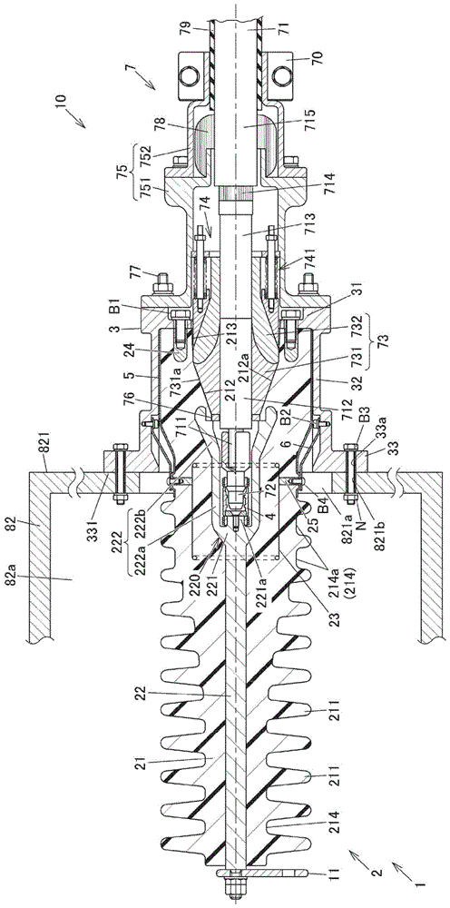
Fig. 1 is an exploded cross-sectional view of a power cable connection structure 10 according to the present embodiment, in which an insulating tube unit 1 and a cable assembly 7 are exploded. Fig. 2 is a sectional view of the power cable connection structure 10. Fig. 3 is an enlarged view of a part of fig. 2.
As shown in fig. 2, the power cable connection structure 10 is used by being attached to an equipment box 82, which is an attached member disposed on a roof of a railway vehicle or the like, for example. The power cable connection structure 10 is attached to the equipment box 82 in a state in which a part thereof protrudes into the internal space 82a in the equipment box 82, and the details thereof will be described below. The power cable connection structure 10 is used for connecting a power cable 71 to which a high voltage is applied and an unshown electrical path connected thereto while securing electrical insulation from the surroundings, and is formed by assembling an insulating tube unit 1 and a cable assembly 7 as shown in fig. 1 and 2.
(insulating tube Unit 1)
The insulating tube unit 1 includes an insulating tube structure 2 integrally formed with an insulating tube 21, and a flange member 3 fixed to the insulating tube structure 2. The insulating tube structure 2 is formed by embedding an internal conductor 22, a ground electrode 23, and the like in an insulating tube 21 made of epoxy resin. The insulating tube structure 2 is formed by integrally forming the insulating tube 21, the inner conductor 22, the ground electrode 23, and the like by disposing the inner conductor 22, the ground electrode 23, and the like inside a molding die of the insulating tube 21 and by pouring a molten epoxy resin into the molding die and curing the epoxy resin.
Note that the axial direction of the insulating tube unit 1 (i.e., the axial direction of the inner conductor 22 and the axial direction of the insulating tube 21, the left-right direction in fig. 1 to 3) is simply referred to as the axial direction. One side in the axial direction, that is, one side (for example, the right side in fig. 1 to 3) of the inner conductor 22 connected to the power cable 71 is referred to as an axial base end side, and the opposite side (for example, the left side in fig. 1 to 3) is referred to as an axial tip end side. In addition, the term "circumferential direction" refers to a circumferential direction around the center axis of the power cable connection structure 10, and the term "radial direction" refers to a radial direction of the power cable connection structure 10 about the center axis.
The inner conductor 22 is formed in a substantially rod shape elongated in the axial direction. The inner conductor 22 is embedded in the insulating tube 21 with its end portion on the axial tip side protruding from the insulating tube 21. The end of the inner conductor 22 protruding from the insulating tube 21 is electrically connected to an unshown electrical path to which the power cable 71 is connected, via the terminal fitting 11 fixed to the exposed portion.
As shown in fig. 3, a bottomed tubular portion 220 that opens on the axial base end side is formed at the end portion on the axial base end side of the inner conductor 22. The bottomed cylindrical portion 220 includes a bottom wall portion 221 and a hollow cylindrical wall portion 222 extending from the bottom wall portion 221 toward the axial base end side.
The outer peripheral surface of the bottom wall 221 is tapered so as to have a larger diameter toward the base end side in the axial direction. The bottom wall 221 is formed with a boss portion 221a that protrudes toward the axial base end side. The boss portion 221a is provided with a female screw hole, and a contact member 4 for detachably connecting the inner conductor 22 and the power cable 71 is fastened by a bolt.
The cylindrical wall portion 222 extends from the outer peripheral edge of the bottom wall portion 221 toward the axial base end side, and surrounds the connection portion between the power cable 71 and the inner conductor 22 via the contact member 4. The cylindrical wall portion 222 includes a cylindrical portion 222a formed straight in the axial direction from the bottom wall portion 221, and an enlarged diameter portion 222b having both an inner diameter and an outer diameter that increase toward the axial base end side from the cylindrical portion 222 a. The inner peripheral surface of the cylindrical wall portion 222 is exposed from the insulating tube 21. The contact member 4 is disposed in the axial cylindrical portion 222a of the bottomed cylindrical portion 220.
As shown in fig. 3, the contact member 4 may be, for example, a Tulip contact (Tulip contact), and detachably connects the inner conductor 22 and the power cable 71. The contact member 4 has: a main body 41 in which conductors elongated in the axial direction are circularly arranged; a fastening spring portion 42 that fastens the body portion 41 to the inner peripheral side; and an annular fixed plate portion 43 fitted to the inner peripheral portion of the main body portion 41. The end portion on the base end side in the axial direction of the body 41 is fitted externally to a connection terminal 72 described below connected to the power cable 71, and the end portion on the tip end side in the axial direction is fitted externally to the boss portion 221a of the inner conductor 22, thereby electrically connecting both the connection terminal 72 and the inner conductor 22. A fastening spring portion 42 is wound around the outer peripheral side of each of the axial both end portions of the contact member 4. The fixing plate portion 43 is fitted to the inner peripheral portion of the body portion 41 at a position on the axial front end side of the connection terminal 72. The contact member 4 is fixed to the inner conductor 22 by inserting a bolt B6 through the through hole 431 formed in the fixing plate portion 43 and screwing it into the female screw hole 22a of the inner conductor 22. The contact member 4 may be configured other than a tulip contact as long as it can electrically relay the power cable 71 and the inner conductor 22.
As shown in fig. 1 and 2, the insulating tube 21 is formed of an epoxy resin in a substantially tubular shape elongated in the axial direction. In particular, when the power cable connection structural body 10 is installed outdoors such as on the roof of a railway vehicle, an epoxy resin having excellent weather resistance is preferably used as the resin constituting the insulating tube 21.
Annular umbrella portions 211 protruding to the outer peripheral side are provided at a plurality of positions in the axial direction X on the outer peripheral portion of the insulating tube 21 at predetermined intervals. By forming the plurality of umbrella-shaped portions 211 in the insulating tube 21, a creeping distance along the outer peripheral surface of the insulating tube 21 can be ensured, and generation of creeping discharge along the surface of the insulating tube 21 can be suppressed. In the present embodiment, the outer diameters of the plurality of umbrella-shaped portions 211 are equal to each other. When the outer diameter of the umbrella portion 211 having the largest outer diameter among the plurality of umbrella portions 211 is set to the largest outer diameter and the outer diameter of the umbrella portion 211 having the smallest outer diameter among the plurality of umbrella portions 211 is set to the smallest outer diameter, the ratio of the largest outer diameter to the smallest outer diameter, that is, "largest outer diameter/smallest outer diameter" is preferably 1.1 or less, and more preferably 1.05 or less. In the present embodiment, the outer diameter of each umbrella-shaped portion 211 is equal to the outer diameter of the end portion on the axial base end side of the insulating tube 21.
An electric field shielding layer 5 is formed on the outer peripheral surface of the insulating tube 21. The electric field shielding layer 5 is formed from the position of the end portion on the axial base end side of the insulating tube 21 to the position in front of the umbrella portion 211 located closest to the axial base end side among the plurality of umbrella portions 211 of the insulating tube 21. In the present embodiment, the electric field shielding layer 5 is formed to the axial front end side of the below-described embedded conductive member 25. The electric field shielding layer 5 is formed on the entire outer peripheral surface of the insulating tube 21. The electric field shielding layer 5 has a function of shielding an electric field in a region on the inner peripheral side thereof to suppress an increase in the electric field strength around the insulating tube 21. The electric field shielding layer 5 is made of, for example, a conductive paint applied to the outer peripheral surface of the insulating tube 21. By providing the electric field shielding layer 5 with a layer made of a conductive coating material, the electric field shielding layer 5 can be reduced in weight and thickness.
The inner peripheral surface of the insulating tube 21 has an arrangement surface 212 for arranging the stress cone 73 in contact therewith. The disposition surface 212 has a shape corresponding to the outer shape of the stress cone 73 disposed inside, and in the present embodiment, has an inclined disposition surface 212a that faces the outer circumferential side at least toward the axial base end side. The inner peripheral surface of the insulating tube 21 includes a cylindrical surface 213 formed in the axial direction from the inclined surface 212a toward the base end side in the axial direction. The axial distal end of the cylindrical surface 213 is also configured as an arrangement surface 212 for the stress cone 73 to be arranged in contact therewith. A plurality of nut members 24 for fixing the insulating tube 21 to the flange are embedded in the insulating tube 21 on the outer peripheral side of the disposition surface 212.
As shown in fig. 3, the nut member 24 is a cap nut that is elongated in the axial direction and is provided with a female screw hole 240 that opens at an end surface on the axial base end side. The end of the nut member 24 on the proximal end side in the axial direction is exposed from the insulating tube 21. The flange member 3 is fastened to each nut member 24 by a bolt B1.
As shown in fig. 2, the flange member 3 is attached to the equipment box 82. The equipment box 82 is at ground potential when installed on the roof of a railway, and accordingly, the flange member 3 is at the same potential as the equipment box 82, that is, at ground potential when the cable connection device is used.
Fig. 4 is a side view of the flange member 3. Fig. 5 is a sectional view of the flange member 3. Fig. 6 is a front view of the flange member 3. Fig. 7 is a rear view of the flange member 3. The flange member 3 is cup-shaped and has a flange bottom wall 31, a flange side wall 32, and a flange mounting wall 33. The flange bottom wall 31 is formed in a disc shape having an opening 311 at the center, and axially faces the end surface of the insulating tube 21 on the axial proximal end side as shown in fig. 3. The bolt B1 is inserted through the through hole 310 provided in the flange bottom wall 31 and screwed into the female screw hole 240 of the nut member 24, thereby fixing the flange member 3 to the insulating tube 21. The flange member 3 is disposed on the axial base end side of the mounting surface 331 with respect to the fixing portion of the insulating tube 21. Therefore, the projecting length of the insulating tube unit 1 projecting from the mounting surface 331 toward the axial front end side (i.e., the internal space 82a of the equipment box 82) can be reduced. In many cases, a plurality of wires are mounted in the equipment box 82, and when the insulating tube unit 1 protrudes largely into the equipment box 82, there is a possibility that electrical insulation from the nearby wires is reduced, but by reducing the protruding length of the insulating tube unit 1 protruding into the internal space 82a of the equipment box 82, reduction in electrical insulation from the nearby wires of the insulating tube unit 1 can be suppressed. Further, it is possible to suppress an increase in size of a portion of the insulating tube unit 1 on the axial front end side of the mounting surface 331 (that is, a portion inserted into the internal space 82a of the equipment box 82). Accordingly, the mounting hole 821a of the equipment box 82 for inserting the mounting surface 331 of the insulating tube unit 1 toward the axial front end can be reduced. In the present embodiment, the mounting surface 331 of the flange member 3 is disposed on the axial base end side of the fixing portion of the insulating tube 21, whereby the mounting hole 821a can be further reduced in size. In other words, the power cable connection structure 10 according to the present embodiment can be inserted into the internal space 82a of the equipment box 82 through the small-diameter mounting hole 821a, and contributes to the demand for downsizing specific to the use of the railway vehicle.
As shown in fig. 4 and 5, the flange side wall 32 is formed in a cylindrical shape. At three circumferential locations on the flange side wall 32, component arrangement portions 321 are formed, the outer circumferential surface of which is raised toward the outer circumferential side and the inner circumferential surface of which is depressed toward the outer circumferential side. A female screw hole 321c that opens to a bottom surface 321b of a recess 321a formed on the inner circumferential side of the member arrangement portion 321 is formed in the member arrangement portion 321. As shown in fig. 3, a bolt B2 is screwed into the internal screw hole 321c, and the below-described link member 6 is fixed to the flange member 3 using this bolt B2.
The axial front end side of the recess 321a is closed by an inclined surface 321 d. The inclined surface 321d is a surface inclined toward the inner peripheral side as it goes toward the axial front end side. By forming the surface on the axial distal end side of the blocking recess 321a as the inclined surface 321d, the space around the connection member 6 can be enlarged, and the connection member 6 can be prevented from interfering with the flange member 3, the insulating tube 21, and the like in the work of fixing the connection member 6 to the flange member 3 and the below-described embedded conductive member 25.
The pair of flange mounting walls 33 are provided so as to protrude from the end portion on the axial front end side of the flange side wall 32 to both sides in the direction orthogonal to the axial direction. The axial front end side surface of each flange mounting wall 33 constitutes a mounting surface 331 on which the equipment box 82 is mounted. As shown in fig. 2 and 3, the insulating tube unit 1 is inserted into the internal space 82a of the equipment box 82 from the mounting hole 821a provided in the equipment box 82, and the mounting surface 331 of the flange mounting wall 33 faces a wall portion around the mounting hole 821a of the equipment box 82.
Bolt insertion holes 33a and 821b communicating with each other are formed in the flange mounting wall 33 and the equipment box 82, respectively. The flange mounting wall 33 and the equipment box 82 are fastened by bolts by inserting the bolts B3 into the bolt insertion holes 33a and the bolt insertion holes 821B and screwing the nuts N to the bolts B3 that protrude from the bolt insertion holes 821B toward the axial base end side. In a state where the flange mounting wall 33 is fastened to the equipment box 82 provided on the roof of the railway, the flange mounting wall 33 has the same potential as the equipment box 82, that is, a ground potential. The ground electrode 23 is embedded in the insulating tube 21 so as to be electrically connected to the flange member 3.
The ground electrode 23 is formed in a cylindrical shape along the axial direction, and surrounds a part of the inner conductor 22 from the outer circumferential side. The ground electrode 23 is entirely embedded in the insulating tube 21 and is not exposed to the outside of the insulating tube 21. In the present embodiment, the ground electrode 23 is formed by forming a metal mesh into a cylindrical shape, and has a plurality of holes (i.e., mesh portions) formed therein. By forming the ground electrode 23 as a member having a plurality of holes formed therein, a molding failure of the insulating tube 21 can be suppressed. That is, the insulating tube 21 is formed by insert molding in which the ground electrode 23 and the like are disposed in a molding die, and during insert molding, the molten epoxy resin constituting the insulating tube 21 flows sufficiently into the inner and outer peripheries of the ground electrode 23 through the mesh of the metal mesh, thereby suppressing the occurrence of molding failure. Both end portions of the ground electrode 23 in the axial direction have a shape wound toward the inner circumferential side. The ground electrode 23 is not limited to a metal mesh, and may be configured such that a plurality of holes such as slits or punched holes are formed in a cylindrical conductor, or a cylindrical conductor without a hole, or may be configured in other structures as long as it can shield an electric field around it.
The end portion of the ground electrode 23 on the axial proximal end side is positioned farther from the axial distal end side than the disposition surface 212. The end portion of the ground electrode 23 on the proximal end side in the axial direction is formed slightly closer to the distal end side in the axial direction than the boundary position between the cylindrical portion 222a and the enlarged diameter portion 222 b. Further, the end portion of the ground electrode 23 on the axial proximal end side is positioned on the axial proximal end side of the mounting surface 331. When viewed in the radial direction, the base end side portion in the axial direction of the ground electrode 23 overlaps the front end side portion in the axial direction of the electric field shielding layer 5.
The end portion of the ground electrode 23 on the axial distal end side is positioned on the axial distal end side of the mounting surface 331. The end portion of the ground electrode 23 on the axial distal end side is positioned on the axial distal end side of the bottom wall portion 221 of the bottomed cylindrical portion 220 of the inner conductor 22. Further, without being limited thereto, the position of the end portion of the ground electrode 23 on the axial distal end side may be located on the axial proximal end side of the boundary between the bottom wall portion 221 of the bottom cylindrical portion 220 and the cylindrical portion 222a, for example.
Further, the position of the end portion on the axial distal end side of the ground electrode 23 is located on the axial proximal end side with respect to the position of the end portion on the axial distal end side of the large-diameter umbrella-like surface 214a described below. The large-diameter umbrella-shaped space 214a is an umbrella-shaped space 214 having an outer diameter larger than other umbrella-shaped spaces 214 among the umbrella-shaped spaces 214 connecting the umbrella-shaped portions 211 adjacent to each other in the axial direction in the outer peripheral surface of the insulating tube 21. In the present embodiment, the large-diameter umbrella surface 214a is the umbrella surface 214 located at the end on the axial base end side of the plurality of umbrella surfaces 214 and the umbrella surface 214 adjacent to the axial tip end side of the umbrella surface. The ground electrode 23 is configured to be able to be electrically connected to the outside of the insulating tube 21 via the embedded conductive member 25 connected thereto.
As shown in fig. 3, the embedded conductive member 25 is a columnar conductor extending radially outward from the ground electrode 23, and is embedded in the insulating tube 21 with its radially outer end exposed. The embedded conductive member 25 is exposed in a region of the outer peripheral surface of the insulating tube 21 where the electric field shielding layer 5 is formed.
Fig. 8 is a side view of the ground electrode 23, the plurality of embedded conductive members 25, and the plurality of connection members 6. The end portion of the embedded conductive member 25 on the ground electrode 23 side is joined to the ground electrode 23 by welding or the like. In the present embodiment, the ground electrode 23 is connected to the embedded conductive members 25 at three circumferential positions. The three embedded conductive members 25 are formed at the same position in the axial direction and are formed at intervals of 90 ° in the circumferential direction. A female screw hole 251 that opens radially outward is formed in the embedded conductive member 25. The connecting member 6 is fastened to the embedded conductive member 25 with a bolt B4.
As shown in fig. 8, three connecting members 6 are provided, and are connected to the three embedded conductive members 25, respectively. The connecting member 6 is formed by bending a long plate-shaped conductor, and includes a first connecting portion 61, an inclined portion 62, and a second connecting portion 63.
As shown in fig. 3, the first connection portion 61 is formed in the axial direction to overlap the embedded conductive member 25 in the radial direction via the electric field shielding layer 5. The first connecting portion 61 is fastened to the embedded conductive member 25 by inserting a bolt B4 through the through hole 611 formed in the first connecting portion 61 and screwing it into the female screw hole 251 of the embedded conductive member 25. In the state where first connection portion 61 is fastened to embedded conductive member 25 with bolt B4, connection member 6, electric field shield layer 5, embedded conductive member 25, and ground electrode 23 are electrically connected to each other.
The inclined portion 62 is formed so as to connect the first connection portion 61 and the second connection portion 63, and is formed so as to be inclined radially outward toward the axial base end side. The inclined portion 62 faces the inclined surface 321d of the flange member 3.
The second connecting portion 63 is formed in the axial direction so as to overlap with a bottom surface 321b of the concave portion 321a of the component arrangement portion 321. The second connecting portion 63 is fastened to the flange member 3 by inserting a bolt B2 through a through hole 631 formed in the second connecting portion 63 and screwing it into a female screw hole 321c provided in the member arrangement portion 321. The second connection portion 63 and the bolt B2 are disposed so as to be received in the member disposition portion 321 of the flange side wall 32. The cable assembly 7 is connected to the insulating tube unit 1 from the proximal end side of the flange member 3.
(Cable component 7)
As shown in fig. 1 and 2, the cable assembly 7 includes a power cable 71, a connection terminal 72, a stress cone 73, a compression device 74, and a cover member 75. The power cable 71 includes, in order from the center, a cable conductor 711, a cable inner semiconductive layer (not shown), a cable insulator 712, a cable outer semiconductive layer 713, a cable shield layer 714, and a cable jacket 715. The power cable 71 is separated into sections so that a cable conductor 711, a cable insulator 712, a cable outer semiconductive layer 713, and a cable shield layer 714 are exposed in this order from the axial front end side.
The connection terminal 72 is crimped to the cable conductor 711 and is fixed to the cable conductor 711 in an attachable and detachable manner. The connection terminal 72 is a terminal for connecting the power cable 71 to the contact member 4, and an end portion on the axial front end side thereof is inserted and fitted into the contact member 4. The connection terminal 72 is detachably connected to the contact member 4 so as to be capable of being press-fitted into the contact member 4 and also capable of being pulled out from the contact member 4.
The stress cone 73 is fitted to the outer periphery of the cable insulator 712 and the cable outer semiconductive layer 713. The stress cone 73 is compressed in the axial direction by the compression device 74, and contacts both the power cable 71 and the arrangement surface 212 of the insulating tube 21.
In the present embodiment, the stress cone 73 is formed of two members, and includes an insulating portion 731 on the axial tip side and a semi-conductive portion 732 on the axial base end side. The outer peripheral surface of the insulating portion 731 has an inclined outer peripheral surface 731a that is inclined from the end on the axial distal end side toward the axial proximal end side, and the inclined outer peripheral surface 731a contacts the inclined arrangement surface 212a of the insulating tube 21. The inner periphery of the semi-conductive portion 732 is in contact with the cable outer semi-conductive layer 713, and is connected to the ground potential via the cable outer semi-conductive layer 713. An annular stopper 76 is fitted to the outer peripheral portion of the power cable 71 on the axial distal end side of the stress cone 73. The stopper 76 receives a compressive force acting on the stress cone 73 in the axial direction from the compression device 74, and abuts against an end surface of the inner conductor 22 on the axial base end side.
The compression device 74 is used to compress the stress cone 73 in the axial direction. The axial distal end of the compression device 74 abuts against the stress cone 73, and the axial proximal end is locked to the cover member 75. Then, the compression device 74 presses the stress cone 73 toward the axial distal end side by the reaction force of the coil spring 741, for example. In the present embodiment, the entire compression device 74 is made of a material having electrical conductivity, but at least a part thereof may be made of a material having no electrical conductivity.
The cover member 75 has a first cover 751 and a second cover 752 fixed to each other. The first cover 751 is fastened to the flange member 3 using a stud bolt 77 or the like screwed to the flange bottom wall 31. In the power cable connection structure 10, the first cover 751 surrounds, from the outer peripheral side, the power cable 71, the stress cone 73, and the compression device 74 protruding from the flange member 3 toward the axial direction base end side. The end of the first cover 751 on the axial proximal end side is sealed from the power cable 71 by a seal 78. The sealing portion 78 is formed by winding a polyethylene tape, an epoxy tape, or the like provided with an adhesive material, and liquid-tightly seals between the first cover 751 and the power cable 71.
The second cover 752 is fixed to the first cover 751 from the axial base end side of the first cover 751, and surrounds the sealing portion 78 from the outer peripheral side. The end portion of the second cover 752 on the proximal end side in the axial direction is fastened by the fastening member 70 and is in close contact with the power cable 71 via the elastic piece 79.
(mounting structure for mounting the power cable connection structure 10 to the roof 81 of the railway vehicle 8)
Fig. 9 is a plan view of the railway vehicle 8 to which the power cable connection structural body 10 is attached. Fig. 10 is a side view of the railway vehicle 8 to which the power cable connection structural body 10 is attached. In fig. 9 and 10, for convenience of explanation, a bolt (see symbol B3 in fig. 2 and 3) and a nut (see symbol N in fig. 2 and 3) for fastening the power cable connection structural body 10 to the equipment box 82 are not shown.
In the railway vehicle 8 to which the power cable connection structural body 10 is to be attached, an equipment box 82 is provided on a roof 81. The equipment box 82 includes a side wall 821 extending in the vertical direction and a lid 822 closing the side wall 821 from above. The side wall 821 is provided with the above-described mounting hole 821a for inserting the power cable connection structure 10.
As shown in fig. 10, since the overhead wire 100 is present on the upper side of the roof 81 of the railway vehicle 8, the height of the side wall 821 is limited. Accordingly, the diameter of the mounting hole 821a that can be formed in the side wall 821 is also limited. Therefore, in particular, in the power cable connection structure 10 to which the equipment box 82 disposed on the roof 81 of the railway vehicle 8 is attached, the demand for downsizing is remarkable so that the installation hole 821a having a small diameter can be inserted into the internal space 82a of the equipment box 82.
Although not shown, various high-voltage devices, high-voltage electrical paths (for example, bus bars), and the like are housed in the internal space 82a of the device case 82, and therefore it is desirable to reduce the amount of protrusion of the insulating tube unit 1 into the internal space 82 a. In particular, in the equipment box 82 disposed on the roof 81 of the railway vehicle 8, since the height is restricted as described above, the restriction of the space of the internal space 82a is significant. Therefore, in the power cable connection structural body 10 mounted to the equipment box 82 disposed on the roof 81 of the railway vehicle 8, in particular, a requirement for reducing the amount of protrusion into the internal space 82a is remarkable.
The power cable 71 exposed outside the equipment box 82 in the power cable connection structure 10 is fixed to the roof 81 of the railway vehicle 8 by using the clip 83. The clamp 83 covers the power cable 71 outside the equipment box 82 from the upper side, and is fastened to the fixed portion 811 of the roof 81 with a bolt B5. The position of the fixed portion 811 on the roof 81 of the railway vehicle 8 may be predetermined for each railway vehicle 8. Therefore, when the position P of the end portion on the axial distal end side of the power cable 71 exposed in the cable assembly 7 is excessively separated from the attachment surface 331 toward the axial proximal end side, it is difficult to fix the power cable 71 to the fixed portion 811 using the clip 83. For example, when the position P is too far apart from the attachment surface 331 toward the axial base end side, and when the cover member 75 or the like having an outer diameter larger than that of the power cable 71 is disposed above the fixed portion 811, it is assumed that the power cable 71 cannot be fixed to the fixed portion 811 by using the clip 83. Therefore, the position P is required not to be excessively separated from the mounting surface 331. Further, since the space above the roof 81 of the railway vehicle 8 is limited, it is also required that the position P is not excessively separated from the mounting surface 331 toward the axial base end side.
In order to satisfy the above-described requirements, in the present embodiment, the positional relationship between the mounting surface 331 and each part of the power cable connection structural body 10 is examined. This will be explained below.
(positional relationship between the mounting surface 331 and each part of the power cable connection structure 10)
Next, the positional relationship between the mounting surface 331 and each part of the power cable connection structural body 10 will be described. The predetermined portion located on the axial front end side or the axial base end side with respect to the mounting surface 331 means: unless otherwise specified, at least a part of the predetermined member is located on the axial front end side or the axial base end side with respect to the mounting surface 331.
As shown in fig. 1 to 3, in the present embodiment, the flange member 3 is positioned on the axial base end side of the mounting surface 331. This can prevent the portion of the insulating tube unit 1 on the axial distal end side of the mounting surface 331 (i.e., the portion inserted into the internal space 82a of the equipment box 82) from becoming larger. Accordingly, the mounting hole 821a of the equipment box 82 for inserting the portion of the insulating tube unit 1 on the axial front end side of the mounting surface 331 can be reduced. In the present embodiment, the mounting hole 821a can be further reduced in size by disposing the entire flange member 3 on the axial base end side of the mounting surface 331.
The disposition surface 212 is located on the axial base end side of the attachment surface 331. In order to allow the stress cone 73 to be inserted, the arrangement surface 212 needs to have a somewhat larger inner diameter, and accordingly, unless otherwise specified, the outer diameter of the axial region of the insulating tube 21 in which the arrangement surface 212 is formed also becomes larger. Therefore, by disposing the disposition surface 212 on the axial proximal end side of the attachment surface 331 with respect to the attachment surface 331, it is possible to suppress the portion of the insulating tube unit 1 on the axial distal end side of the attachment surface 331 (i.e., the portion inserted into the internal space 82a of the equipment box 82) from becoming large. Along with this, the mounting hole 821a of the equipment box 82 can be reduced. In the present embodiment, the mounting hole 821a can be further reduced in size by disposing the entire disposition surface 212 on the axial base end side of the mounting surface 331.
Further, by disposing the flange member 3 and the disposition surface 212 at the axial base end side of the attachment surface 331, the portion of the insulating tube unit 1 from the attachment surface 331 to the axial tip end side can be suppressed from becoming long in the axial direction. This can prevent the insulating tube unit 1 from protruding largely into the internal space 82a of the equipment box 82.
The contact member 4 is located on the axial front end side of the mounting surface 331. This allows the entire position of the cable assembly 7 to be arranged closer to the axial distal end side with respect to the mounting surface 331. Accordingly, the position P closest to the axial distal end side of the power cable 71 exposed in the cable assembly 7 can be prevented from being largely separated from the mounting surface 331 toward the axial proximal end side. In the present embodiment, the entire contact member 4 is disposed on the axial front end side of the mounting surface 331. Therefore, the position P can be set closer to the mounting surface 331.
The ground electrode 23 is located on the axial front end side of the mounting surface 331. The ground electrode 23 relaxes the electric field around the insulating tube 21 by shielding the electric field in the region on the inner peripheral side thereof, and therefore by burying the ground electrode 23 in the insulating tube 21, the outer diameter around the ground electrode 23 in the insulating tube 21 can be reduced. Therefore, by disposing the ground electrode 23 on the axial distal end side of the mounting surface 331, it is possible to suppress the portion of the insulating tube 21 on the axial distal end side of the mounting surface 331 (that is, the portion inserted into the internal space 82a of the equipment box 82) from becoming larger. Accordingly, the mounting hole 821a of the equipment box 82 can be reduced. In the present embodiment, the region of the ground electrode 23 that exceeds half of the region in which the ground electrode 23 is formed in the axial direction is disposed on the axial direction leading end side of the mounting surface 331. Accordingly, the electric field around the insulating tube 21 can be further relaxed in the region on the axial front end side of the mounting surface 331, and the outer diameter of the insulating tube 21 from the mounting surface 331 to the axial front end side can be reduced to a smaller diameter. Accordingly, the mounting hole 821a can be further reduced.
The ground electrode 23 is disposed at a position across the mounting surface 331 in the axial direction. That is, the end portion on the axial distal end side of the ground electrode 23 is positioned on the axial distal end side of the mounting surface 331, and the end portion on the axial proximal end side thereof is positioned on the axial proximal end side of the mounting surface 331. Therefore, leakage of an electric field from the axial direction base end side of the ground electrode 23 to the vicinity of the mounting surface 331 outside the insulating tube 21 can be suppressed, and the electric field in the vicinity of the mounting surface 331 can be further alleviated.
The mounting surface 331 is disposed on the axial front end side of the connection terminal 72 connected to the contact member 4. As a result, the entire position of the cable assembly 7 can be arranged closer to the axial distal end side than the mounting surface 331, and as a result, the position P can be prevented from being largely separated from the mounting surface 331 toward the axial proximal end side. The connection terminal 72 is formed so as to straddle the mounting surface 331 at a position in the axial direction. That is, the end on the axial distal end side of the connection terminal 72 is positioned on the axial distal end side of the mounting surface 331, and the end on the axial proximal end side thereof is positioned on the axial proximal end side of the mounting surface 331. More specifically, the connection terminal 72 is inserted into the contact member 4 at a position on the axial front end side of the mounting surface 331, and is crimped to the cable conductor 711 of the power cable 71 at a position on the axial base end side of the mounting surface 331. The connection terminal 72 is formed so as to straddle the position of the mounting surface 331 in the axial direction, and therefore, it is possible to suppress the position of the connection terminal 72 from being excessively separated toward the axial tip side with reference to the mounting surface 331 and to suppress the insulating tube unit 1 from excessively protruding from the mounting surface 331 toward the axial tip side.
Further, the inner conductor 22 has an axial cylindrical portion 222a disposed on the axial distal side of the mounting surface 331, and has an enlarged diameter portion 222b disposed on the axial proximal side of the mounting surface 331. That is, the axial cylindrical portion 222a having a smaller outer diameter is positioned on the axial distal end side of the attachment surface 331, and the enlarged diameter portion 222b having a larger outer diameter is positioned on the axial proximal end side of the attachment surface 331. This can suppress an increase in the outer diameter of the portion of the insulating tube unit 1 from the mounting surface 331 to the axial distal end side (i.e., the portion inserted into the internal space 82a of the equipment box 82). As a result, the mounting hole 821a can be reduced. The axial cylindrical portion 222a is disposed at a position in the axial direction across the mounting surface 331, and the entire diameter-expanded portion 222b is disposed on the axial base end side of the mounting surface 331.
The embedded conductive member 25 is exposed from the insulating tube 21 at a position closer to the axial front end side than the mounting surface 331. In the present embodiment, the entire embedded conductive member 25 is disposed on the axial front end side of the mounting surface 331. Therefore, in a state where the flange member 3 is fixed to the insulating pipe 21, the connecting member 6 can be fastened to the embedded conductive member 25 using the bolt B4.
The connecting member 6 electrically connected to the embedded conductive member 25 and the flange member 3 is fixed to the inner peripheral side of the flange side wall 32. Therefore, a region in which the electric field strength becomes high can be prevented from being formed in the equipment box 82. For example, when the connection member 6 is fixed to the mounting surface 331 of the flange member 3, a bolt or the like for fixing the connection member 6 may protrude from the mounting surface 331 into the equipment box 82, and the electric field intensity around the bolt may be increased. Accordingly, by fixing the connection member 6 to the inner peripheral side of the flange side wall 32, it is possible to suppress formation of a portion in the equipment box 82 where the electric field strength increases due to the bolt B2 or the like for fixing the connection member 6 to the flange member 3 projecting largely into the equipment box 82.
(operation and Effect of the embodiment)
In the present embodiment, the end portion of the ground electrode 23 on the axial proximal end side is positioned on the axial distal end side with respect to the arrangement surface 212 on which the stress cone 73 is arranged. Therefore, the insulating tube 21 can be downsized. This will be explained below.
First, the arrangement surface 212 needs to have a somewhat larger inner diameter in order to be inserted into the stress cone 73 attached to the power cable 71, and accordingly, the outer diameter of the axial region of the insulating tube 21 in which the arrangement surface 212 is formed also needs to be larger. Further, if the respective portions of the insulating tube 21 on the inner and outer peripheral sides of the ground electrode 23 are too thin, problems in manufacturing such as short-shots may occur, and thus a certain thickness is required. Therefore, when the ground electrode 23 is formed to a position overlapping the arrangement surface 212 as viewed in the radial direction, the outer diameter of the insulator 21 has to be increased in an axial region where the ground electrode 23 overlaps the arrangement surface 212 in the radial direction, which may increase the size of the insulator 21. On the other hand, in the present embodiment, as described above, the end portion of the ground electrode 23 on the base end side in the axial direction is positioned on the tip end side in the axial direction with respect to the arrangement surface 212, and therefore, the insulator 21 can be downsized.
An electric field shielding layer 5 for shielding an electric field is formed on the outer peripheral surface of the insulating tube 21 on the axial proximal side of the ground electrode 23. Therefore, the electric field is shielded by the electric field shielding layer 5 in the region of the insulating tube 21 on the axial proximal side of the ground electrode 23. In the present embodiment, the ground electrode 23 and the electric field shielding layer 5 partially overlap each other when viewed in the radial direction. Therefore, the electric field can be shielded in a large axial region from the end portion on the axial distal side of the ground electrode 23 to the end portion on the axial proximal side of the electric field shielding layer 5, and as a result, the electric field strength around the insulating tube 21 can be suppressed from increasing.
The insulating tube unit 1 further includes a flange member 3. The disposition surface 212 is disposed on the axial base end side of the attachment surface 331. Therefore, the protruding length of the insulating tube unit 1 protruding from the mounting surface 331 toward the axial front end side (i.e., the internal space 82a of the equipment box 82) can be reduced. In many cases, a plurality of wires are mounted in the equipment box 82, and when the insulating tube unit 1 protrudes largely into the equipment box 82, there is a possibility that electrical insulation from the nearby wires is reduced, but by reducing the protruding length of the insulating tube unit 1 protruding into the internal space 82a of the equipment box 82, reduction in electrical insulation from the nearby wires of the insulating tube unit 1 can be suppressed. The ground electrode 23 is disposed on the axial front end side of the mounting surface 331. Therefore, the electric field in the insulating tube 21 protruding into the equipment box 82 can be shielded.
The connecting member 6 electrically connected to the embedded conductive member 25 and the flange member 3 is fixed to the inner peripheral side of the flange side wall 32. Therefore, a region in which the electric field strength becomes high can be prevented from being formed in the equipment box 82. For example, when the connection member 6 is fixed to the mounting surface 331 of the flange member 3, the bolts or the like for fixing the connection member 6 may protrude from the mounting surface 331 into the equipment box 82, and the electric field intensity around the bolts may be increased. Accordingly, by fixing the connection member 6 to the inner peripheral side of the flange side wall 32, it is possible to suppress formation of a portion in the equipment box 82 where the electric field intensity increases due to the large projection of the bolt B2 or the like for fixing the connection member 6 to the flange member 3 into the equipment box 82.
As described above, according to the present embodiment, it is possible to provide an insulating tube unit in which the insulating tube can be downsized.
(summary of the embodiments)
Next, the technical idea grasped from the above-described embodiments will be described with reference to the symbols and the like in the embodiments. In the following description, the reference numerals and the like do not limit the components in the claims to those specifically shown in the embodiments.
[1] An insulating tube unit 1 is provided with: an inner conductor 22 electrically connected to a distal end of the power cable 71; an insulating tube 21 covering the inner conductor 22; and a ground electrode 23 which is embedded inside the insulating tube 21 and is formed so as to surround the inner conductor 22, wherein an inner peripheral surface of the insulating tube 21 has an arrangement surface 212 on which a stress cone 73 attached to the power cable 71 is arranged, and when a side of the inner conductor 22 to which the distal end of the power cable 71 is connected is a base end side and a side opposite to the base end side is a tip end side, an end portion of the ground electrode 23 on the base end side is located on the tip end side with respect to the arrangement surface 212.
[2] The insulating tube unit 1 according to the above [1], wherein an electric field shielding layer 5 for shielding an electric field is formed on the outer peripheral surface of the insulating tube 21 on the base end side of the ground electrode 23.
[3] The insulated pipe unit 1 according to item [2], wherein the ground electrode 23 and the electric field shielding layer 5 partially overlap each other when viewed in a radial direction.
[4] The insulating tube unit 1 according to any one of the above items [1] to [3], further comprising a flange member 3, the flange member 3 having a mounting surface 331 to which an external member 82 to be mounted is mounted and being fixed to the insulating tube 21, wherein the disposition surface 212 is disposed on the base end side of the mounting surface 331, and the ground electrode 23 is disposed on the tip end side of the mounting surface 331.
[5] The insulating tube unit 1 according to the above [4], further comprising: an embedded conductive member 25 which is partially exposed, is embedded in the insulating tube 21, and is electrically connected to the ground electrode 23; and a connecting member 6 electrically connected to the embedded conductive member 25 and the flange member 3, wherein the flange member 3 includes: a flange mounting wall 33 having the mounting surface 331; and a flange side wall 32 formed on the base end side from the flange mounting wall 33 and surrounding the insulating tube 21, wherein the connecting member 6 is fixed to an inner peripheral side of the flange side wall 32.
[6] An insulating tube unit 1 for a railway vehicle 8 includes: an inner conductor 22 electrically connected to a distal end of the power cable 71; a contact member 4 attached to the inner conductor 22 and electrically connecting the power cable 71 and the inner conductor 22; an insulating tube 21 covering the inner conductor 22; a ground electrode 23 embedded inside the insulating tube 21 and formed to surround the inner conductor 22; and a flange member 3 having an attachment surface 331 to be attached to an externally attached member and fixed to the insulating tube 21, wherein an inner peripheral surface of the insulating tube 21 has an arrangement surface 212 on which a stress cone 73 attached to the power cable 71 is arranged, and when a side of the inner conductor 22 to which the distal end of the power cable 71 is connected is a base end side and a side opposite to the base end side is a tip end side, the flange member 3 and the arrangement surface 212 are positioned on the base end side with respect to the attachment surface 331, and the contact member 4 and the ground electrode 23 are positioned on the tip end side with respect to the attachment surface 331.
[7] The insulating tube unit 1 according to item [6], wherein the flange member 3 has: a flange bottom portion 31 that faces the surface of the base end side of the insulating tube 21 and is fixed to the insulating tube 21; a flange side wall 32 formed on the tip end side from the flange bottom 31; and a flange attachment portion 33 formed on an outer peripheral side of the flange member 3 from the flange side wall 32 and having the attachment surface 331 on a surface on the tip end side.
[8] The insulating tube unit 1 according to any one of [6] and [7], wherein the entire contact member 4 is disposed on the distal end side of the mounting surface 331.
[9] The insulating tube unit 1 according to any one of [6] to [8], wherein the ground electrode 23 is disposed so as to straddle the position of the mounting surface 331 in the axial direction.
[10] The insulated pipe unit 1 according to any one of [6] to [9], wherein a region of the ground electrode 23 that exceeds a half of a region in which the ground electrode 23 is formed in an axial direction is disposed on the front end side of the mounting surface 331.
[11] The insulating tube unit 1 according to any one of [6] to [10], wherein the entire flange member 3 is disposed on the base end side of the mounting surface 331.
[12] The insulating tube unit 1 according to any one of [6] to [11], wherein a bottomed cylindrical portion 220 having a bottom wall portion 221 and a cylindrical wall portion 222 extending from the bottom wall portion 221 toward the base end side is formed at an end portion on the base end side of the inner conductor 22, the contact member being disposed inside the bottomed cylindrical portion 220, the cylindrical wall portion 222 having an axial cylindrical portion 222a formed in an axial direction from the bottom wall portion 221 and an enlarged diameter portion 222b having an inner diameter and an outer diameter that become larger from the axial cylindrical portion 222a toward the base end side, the axial cylindrical portion 222a being disposed at a position closer to the distal end side than the mounting surface 331, and the enlarged diameter portion 222b being disposed at a position closer to the base end side than the mounting surface 331.
[13] The insulated pipe unit 1 according to any one of [6] to [12], further comprising an embedded conductive member 25, wherein the embedded conductive member 25 is embedded in the insulated pipe 21 while exposing a part thereof, and is electrically connected to the ground electrode 23, and wherein the embedded conductive member 25 is exposed from the insulated pipe 21 at a position closer to the distal end side than the mounting surface 331.
[14] The insulated pipe unit 1 according to any one of [6] to [13], wherein an electric field shielding layer 5 made of a conductive paint for shielding an electric field is formed on the outer peripheral surface of the insulated pipe 21 on the base end side of the ground electrode 23.
[15] The insulating tube unit 1 as recited in item [14], wherein a part of the electric field shielding layer 5 is formed at a position overlapping the ground electrode 23 in a radial direction.
[16] The insulating tube unit 1 according to any one of [6] to [15], wherein a portion from the mounting surface 331 to the distal end side is inserted into the equipment box 82 from a mounting hole 821a provided in a side wall 821 of the equipment box 82 as the mounted member, the equipment box 82 is provided on a roof 81 of a railway vehicle 8, and the power cable 71 is fixed to the roof 81 using a clip 83 outside the equipment box 82.
[17] The insulating tube unit 1 according to any one of [6] to [16], further comprising: an embedded conductive member 25 which is partially exposed, is embedded in the insulating tube 21, and is electrically connected to the ground electrode 23; and a connecting member 6 electrically connected to the embedded conductive member 25 and the flange member 3, wherein the flange member 3 includes: a flange mounting portion 33 having the mounting surface 331; and a flange side wall 32 formed on the base end side from the flange mounting portion 33 and surrounding the insulating tube 21, wherein the connecting member 6 is fixed to an inner peripheral side of the flange side wall 32.
[18] A power cable connection structure 10 for a railway vehicle 8, comprising an insulating tube unit 1 as recited in any one of [6] to [17] and a cable assembly 7 assembled to the insulating tube unit 1, wherein the cable assembly 7 comprises the power cable 71, a connection terminal 72 electrically connected to a cable conductor 711 exposed in the power cable 71, and the stress cone 73, and wherein the connection terminal 72 is electrically connected to the contact member 4 and is positioned on the front end side of the mounting surface 331.
[19] The power cable connection structure 10 for a railway vehicle 8 according to [18], wherein the connection terminal 72 is disposed at a position across the mounting surface 331 in the axial direction.
(attached note)
The embodiments of the present invention have been described above, but the embodiments described above do not limit the invention of the claims. Note that all combinations of the features described in the embodiments are not necessarily essential to the means for solving the problem of the invention. The present invention can be implemented by being appropriately modified within a range not departing from the gist thereof.