CN114770125A - Punching equipment for automobile part production - Google Patents
Punching equipment for automobile part production Download PDFInfo
- Publication number
- CN114770125A CN114770125A CN202210496986.0A CN202210496986A CN114770125A CN 114770125 A CN114770125 A CN 114770125A CN 202210496986 A CN202210496986 A CN 202210496986A CN 114770125 A CN114770125 A CN 114770125A
- Authority
- CN
- China
- Prior art keywords
- punching
- sliding
- clamping
- shaft
- polishing
- Prior art date
- Legal status (The legal status is an assumption and is not a legal conclusion. Google has not performed a legal analysis and makes no representation as to the accuracy of the status listed.)
- Withdrawn
Links
- 238000004080 punching Methods 0.000 title claims abstract description 101
- 238000004519 manufacturing process Methods 0.000 title claims abstract description 5
- 238000005498 polishing Methods 0.000 claims abstract description 35
- 239000007921 spray Substances 0.000 claims abstract description 22
- 238000005553 drilling Methods 0.000 claims abstract description 4
- 238000001816 cooling Methods 0.000 claims abstract 2
- 239000000110 cooling liquid Substances 0.000 claims description 4
- 230000033001 locomotion Effects 0.000 claims description 4
- 238000009434 installation Methods 0.000 description 4
- 230000000712 assembly Effects 0.000 description 1
- 238000000429 assembly Methods 0.000 description 1
- 230000009286 beneficial effect Effects 0.000 description 1
- 230000005540 biological transmission Effects 0.000 description 1
- 238000001125 extrusion Methods 0.000 description 1
- 230000013011 mating Effects 0.000 description 1
- 239000007769 metal material Substances 0.000 description 1
- 238000000034 method Methods 0.000 description 1
- 238000007517 polishing process Methods 0.000 description 1
- 238000005507 spraying Methods 0.000 description 1
Images


Classifications
-
- B—PERFORMING OPERATIONS; TRANSPORTING
- B23—MACHINE TOOLS; METAL-WORKING NOT OTHERWISE PROVIDED FOR
- B23P—METAL-WORKING NOT OTHERWISE PROVIDED FOR; COMBINED OPERATIONS; UNIVERSAL MACHINE TOOLS
- B23P23/00—Machines or arrangements of machines for performing specified combinations of different metal-working operations not covered by a single other subclass
- B23P23/04—Machines or arrangements of machines for performing specified combinations of different metal-working operations not covered by a single other subclass for both machining and other metal-working operations
Landscapes
- Physics & Mathematics (AREA)
- Optics & Photonics (AREA)
- Engineering & Computer Science (AREA)
- Mechanical Engineering (AREA)
- Jigs For Machine Tools (AREA)
Abstract
The invention discloses punching equipment for automobile part production, which relates to the technical field of punching equipment and comprises a clamping part, a punching part and a punching head, wherein the clamping part is used for clamping a workpiece; further comprising: the punching component is used for punching and polishing, the punching component comprises a punching assembly and a polishing assembly, the punching component also comprises a gear ring, and the punching assembly and the polishing assembly are both arranged at one end of the gear ring; the punching assembly comprises a punching shaft, and a matching spline is arranged on the punching shaft; the polishing assembly comprises a rotating ring and a matching sleeve, a polishing cutter for polishing is movably connected to the bottom end of the rotating ring, the matching sleeve is sleeved on the drilling shaft, a spline groove is formed in the end face, facing the matching spline, of the matching sleeve, and when the matching spline is matched with the spline groove in the matching sleeve, the polishing assembly is driven; the two spray pipes are used for cooling and are respectively positioned on two sides of the clamping part; the invention can realize the punching and polishing operation and adjust the angle of the hole position in the oblique direction.
Description
Technical Field
The invention relates to the technical field of punching equipment, in particular to punching equipment for producing automobile parts.
Background
Automobile parts serve as the basis of the automobile industry, play an important role in the continuous and healthy development process of the automobile industry, particularly, a strong part system is needed to support the independent development and innovation which is vigorously and vigorously developed in the current automobile industry, and a punching machine is needed to be used when automobile parts are machined, wherein the punching machine is automatic equipment which is driven by a motor to machine holes in a metal material. At present, for shell parts on automobiles, the hole sites are large in quantity and wide in arrangement positions, and are arranged in a vertical direction and an oblique direction, the existing punching machine on the market generally realizes punching operation in the vertical direction, and for holes in the oblique direction, the holes can only be transferred to other equipment for processing; in addition, the current punching operation and the polishing process are independent from each other and cannot be performed on the same equipment, so that the processing efficiency is influenced.
The Chinese patent with the publication number of CN109482928B discloses a perforating machine for automobile parts, which comprises a workbench, wherein an adjusting hole is formed in the center of the top of the workbench, an arc-shaped fixed shell is arranged above the workbench, two ends of the fixed shell are fixedly connected with the top of the workbench, two ends of the fixed shell are located at the edges of the adjusting hole, an arc-shaped strip matched with the fixed shell is connected to the inner wall of the fixed shell in a sliding mode, one end of the arc-shaped strip penetrates through the adjusting hole, an arc-shaped limiting groove is formed in the inner wall of the fixed shell, a limiting strip matched with the limiting groove is formed in the side wall of the arc-shaped strip, the limiting strip is connected with the inner wall of the limiting groove in a sliding mode, a plurality of first gear teeth are uniformly distributed on the outer convex side face of the arc-shaped strip, a convex portion is arranged at the top of the fixed shell, and a rotary groove communicated with the fixed shell is formed in the convex portion. In the prior art, polishing operation cannot be performed after drilling, and clamping is inconvenient; and the angle adjustment cannot be performed.
Disclosure of Invention
The technical scheme provided by the invention can solve the technical problems, realize punching and polishing operation and adjust the angle of the hole position in the oblique direction.
A punching device for automobile part production comprises a clamping component, a punching component and a punching component, wherein the clamping component is used for clamping a workpiece; further comprising: the punching component is used for punching and polishing, the punching component comprises a punching assembly and a polishing assembly, the punching component also comprises a gear ring, and the punching assembly and the polishing assembly are both arranged at one end of the gear ring; the punching assembly comprises a punching shaft, a matching spline is arranged on the punching shaft, and punching is carried out through axial and rotary motion of the punching shaft; the polishing assembly comprises a rotating ring and a matching sleeve, a polishing cutter for polishing is movably connected to the bottom end of the rotating ring, the matching sleeve is sleeved on the drilling shaft, a spline groove is formed in the end face, facing the matching spline, of the matching sleeve, and when the matching spline is matched with the spline groove in the matching sleeve, the polishing assembly is driven; the two spray pipes are respectively positioned at two sides of the clamping part, and cooling liquid is respectively sprayed on the rod body and the end part of each spray pipe so as to cool the workpiece and the punching part which are positioned on the clamping part; and the driving assembly is used for driving the clamping component to clamp the workpiece and driving the spray pipe to deflect by an angle.
Furthermore, the driving assembly comprises a screw rod and a third gear, one end of the screw rod is connected with the third gear in a sliding mode, and when one end of the screw rod, facing the clamping component, extrudes to push the clamping component, the screw rod drives the clamping component to clamp the workpiece; the screw rod is rotatably connected with a sliding frame, and the sliding frame is rotatably connected with a second sliding shaft; the driving assembly further comprises a first sliding shaft, the first sliding shaft is connected with the second sliding shaft in a sliding mode, one end of the first sliding shaft is fixedly connected with a gear four, and the gear four and the gear three form a gear pair; and a matching spline shaft is arranged on the end face of one of the spray pipes, and when the spray pipes move to the matching spline shaft through the second sliding shaft and are matched with the matching spline shaft, the two spray pipes are driven to deflect at an angle.
Furthermore, two belt structures are respectively arranged on the two spray pipes, and the two belt structures are connected through a connecting shaft.
Furthermore, the clamping part comprises a clamping seat, a clamping slide seat used for clamping is arranged on the clamping seat in a sliding mode, a second spring used for providing elastic force is arranged between the clamping slide seat and the clamping seat, and one end of the clamping slide seat is an arc-surface end.
Furthermore, the clamping component also comprises a top barrel, wherein a chute is arranged on the top barrel, a top rod is connected in the chute in a sliding manner, and the top barrel moves when the top rod is pushed by one end of a screw rod; the cambered surface end of the clamping sliding seat is in surface contact with the top cylinder, and when the top cylinder moves, the clamping sliding seat is extruded by the top cylinder and moves so as to clamp a workpiece.
Furthermore, the punching part further comprises a fixed mounting rack arranged on one end of the gear ring, the fixedly connected with punching driving motor for driving the punching assembly and the polishing assembly is arranged on the mounting rack, the punching shaft is arranged on an output shaft of the punching driving motor in a sliding manner, a depth cylinder for controlling the punching depth is fixedly arranged on the mounting rack, a push ring is fixedly connected on a push rod of the depth cylinder, and the push ring is connected with the top of the punching shaft in a rotating manner.
Furthermore, the polishing assembly further comprises a sliding cylinder II rotatably mounted on the rotating ring, the sliding cylinder II is connected with a sliding cylinder I in a sliding mode, one end of the sliding cylinder I is rotatably connected with the matching sleeve, a connecting rod is rotatably connected to one end of the sliding cylinder II, and one end, facing the polishing cutter, of the connecting rod is movably connected with the polishing cutter.
Compared with the prior art, the invention has the beneficial effects that: (1) the invention can realize the oblique punching operation of the workpiece by adjusting the azimuth angle of the punching component; (2) according to the invention, the burrs at the top of the hole can be polished and removed through the polishing component.
Drawings
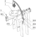
FIG. 1 is a schematic view of the overall structure of the present invention.
FIG. 2 is a schematic view of a clamping member according to the present invention.
FIG. 3 is an enlarged view of a portion of FIG. 2 marked with the letter A.
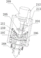
FIG. 4 is a schematic view of the structure of the punching unit of the present invention.
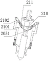
Figure 5 is a schematic view of the installation of the sanding and perforating assemblies of the present invention.
Reference numerals are as follows: 1-a clamping seat; 2-a perforating component; 3-spraying a pipe; 101, a first motor; 102-a clamping slide; 103-top cylinder; 104-a top rod; 105-spring one; 106-spring two; 107-gear one; 201-motor two; 202-gear two; 203-a gear ring; 204-push ring; 205-a perforating shaft; 206-swivel; 207-connecting rod; 208-grinding the cutter; 209-punching driving motor; 210-a mating sleeve; 211-a spool spring; 212-depth cylinder; 213-a mounting frame; 2101-sliding cylinder one; 2102-sliding cylinder two; 2051-mating splines; 301-a first belt structure; 302-a connecting shaft; 303-controlling the motor; 304-a second belt structure; 305-gear three; 306-gear four; 307-a first sliding shaft; 308-a carriage; 309-a screw rod; 310-a third belt structure; 311-mating spline shafts; 312-second sliding shaft.
Detailed Description
The technical solutions in the embodiments of the present invention will be clearly and completely described below with reference to the drawings in the embodiments of the present invention, and it is obvious that the described embodiments are only a part of the embodiments of the present invention, and not all of the embodiments. All other embodiments, which can be derived by a person skilled in the art from the embodiments given herein without making any creative effort, shall fall within the protection scope of the present invention.
As shown in fig. 1, 2 and 3, for the clamping component, the clamping base 1 is rotatably mounted on the frame, a first motor 101 is fixedly mounted on the frame, a first gear 107 is fixedly connected to an output shaft of the first motor 101, the first gear 107 and the bottom end of the clamping base 1 form a gear pair, a clamping slide base 102 is slidably mounted on the clamping base 1, a second spring 106 for providing elastic force is arranged between the clamping slide base 102 and the clamping base 1, one end of the clamping slide base 102 is an arc end, a top cylinder 103 is slidably mounted on the frame, the top cylinder 103 is in contact with the arc end of the clamping slide base 102, a chute is arranged on the top cylinder 103, a push rod 104 is slidably connected in the chute, and a first spring 105 for providing elastic force is connected between the push rod 104 and the frame.
The two spray pipes 3 are rotatably mounted on the rack and located on two sides of the clamping seat 1, and the two spray pipes 3 are respectively connected with a belt structure; the first belt structure 301 and the third belt structure 310 are connected through a connecting shaft 302, and the connecting shaft 302 is rotatably mounted on the rack; the body and the end of the nozzle 3 are sprayed with cooling liquid respectively to cool the workpiece and the punching component 2 on the holder 1.
The driving assembly comprises a screw rod 309 movably mounted on the rack, the screw rod 309 and the rack form a screw pair, one end of the screw rod 309 is connected with a third gear 305 in a sliding manner, the third gear 305 is rotatably mounted on the rack, and when one end of the screw rod 309 facing to the clamping part extrudes and pushes the ejector rod 104, the clamping part is driven to clamp a workpiece; a sliding frame 308 is rotatably connected to the screw rod 309, the sliding frame 308 is slidably mounted on the rack, and a second sliding shaft 312 is rotatably connected to the sliding frame 308; a first sliding shaft 307 is rotatably mounted on the frame, the first sliding shaft 307 is slidably connected with the carriage 308, one end of the first sliding shaft 307 is fixedly connected with a fourth gear 306, and the fourth gear 306 and a third gear 305 form a gear pair; the third gear 305 is connected with a second belt structure 304, the rack is fixedly provided with a control motor 303, an output shaft of the control motor 303 is connected with the second belt structure 304, a matching spline shaft 311 is arranged on the end face of one of the spray pipes 3, and the second slide shaft 312 moves to the matching spline shaft 311 and is matched with the matching spline shaft 311 to drive the two spray pipes 3 to perform angle deflection.
As shown in fig. 1, 4 and 5, for the punching component 2, a second motor 201 is fixedly installed on the frame, a second gear 202 is fixedly connected to an output shaft of the second motor 201, a gear ring 203 is movably installed on the frame, the second gear 202 and the gear ring 203 form a gear pair, one end of the punching component 2 is fixedly connected with an installation frame 213, the installation frame 213 is fixedly provided with a punching driving motor 209 and a depth cylinder 212, an output shaft of the punching driving motor 209 is slidably provided with a punching shaft 205, the punching shaft 205 is provided with a matching spline 2051, the punching shaft 205 is sleeved with a matching sleeve 210, an end surface of the matching sleeve 210 facing the matching spline 2051 is provided with a spline groove, a push rod of the depth cylinder 212 is fixedly connected with a push ring 204, the push ring 204 is rotatably connected with the top end of the punching shaft 205, for the polishing component, a rotary ring 206 is rotatably installed on the installation frame 213, and a polishing cutter 208 is rotatably installed at the bottom end of the rotary ring 206, a second sliding barrel 2102 is rotatably mounted on the rotating ring 206, a first sliding barrel 2101 is slidably connected to the second sliding barrel 2102, a sliding barrel spring 211 used for providing elastic force is arranged between the second sliding barrel 2102 and the first sliding barrel 2101, one end of the matching sleeve 210 is rotatably connected with the matching sleeve 210, a connecting rod 207 is rotatably connected to one end of the second sliding barrel 2102, and one end of the connecting rod 207 facing the grinding cutter 208 is movably connected with the grinding cutter 208.
In carrying out the invention: placing a workpiece on the clamping seat 1, starting the control motor 303, rotating the gear three 305 under the transmission of a belt, rotating the gear four 306 and the first sliding shaft 307 under the engagement of the gear, so as to rotate the screw rod 309, axially moving the screw rod 309 under the connection of a screw pair, so as to slide the carriage 308, enabling the carriage 308 to carry the second sliding shaft 312 to move, and when one end of the screw rod 309 is in extrusion contact with the ejector rod 104, moving the ejector rod 104 on the top cylinder 103 in an inclined groove manner, so as to enable the top cylinder 103 to move and extrude the clamping sliding seat 102, so as to enable the clamping sliding seat 102 to radially move and carry out clamping operation on the workpiece; meanwhile, when one end of the second sliding shaft 312 is matched with the matched spline shaft 311 on one of the spray pipes 3, the two spray pipes 3 deflect at an angle under the drive of the belt, so that the cooling liquid can be sprayed to the workpiece and the grinding assembly during the punching operation.
When the second motor 201 is started, under the meshing of gears, the gear ring 203 moves, the angle position of the punching component 2 can be adjusted, so that the oblique punching operation on a workpiece is realized, when punching is performed, the punching driving motor 209 and the depth cylinder 212 are started, the punching shaft 205 rotates, axial movement is performed under the action of the depth cylinder 212, when the punching shaft 205 moves towards the punching direction, the matching sleeve 210 cannot rotate along with the punching shaft 205, after punching is completed, the punching shaft 205 is far away from a punching area, so that the matching spline 2051 on the punching shaft 205 is matched with the spline groove on the matching sleeve 210, the punching shaft 205 carries the matching sleeve 210 to perform axial movement and rotation, under the connection of the first sliding cylinder 2101 and the second sliding cylinder 2102, the connecting rod 207 moves, and under the connection of the connecting rod 207, the grinding cutter 208 rotates by a preset angle; it should be noted that the grinding tool 208 is located outside the punching shaft 205, and when the punching shaft 205 is separated from the punching area, and the grinding tool 208 is deflected, the area for grinding on the grinding tool 208 is close to the top of the hole and comes into contact with the top of the hole, so as to grind the top area of the hole and remove burrs.
It will be evident to those skilled in the art that the invention is not limited to the details of the foregoing illustrative embodiments, and that the present invention may be embodied in other specific forms without departing from the spirit or essential attributes thereof. The present embodiments are therefore to be considered in all respects as illustrative and not restrictive, the scope of the invention being indicated by the appended claims rather than by the foregoing description, and all changes which come within the meaning and range of equivalency of the claims are therefore intended to be embraced therein, and any reference signs in the claims are not intended to be construed as limiting the scope of the claims.
Claims (7)
1. A punching device for automobile part production comprises a clamping component, a punching component and a punching component, wherein the clamping component is used for clamping a workpiece; it is characterized by also comprising:
the punching component (2) is used for punching and polishing, the punching component (2) comprises a punching assembly and a polishing assembly, the punching component (2) further comprises a gear ring (203), and the punching assembly and the polishing assembly are both arranged at one end of the gear ring (203); the punching assembly comprises a punching shaft (205), a matching spline (2051) is arranged on the punching shaft (205), and punching is performed through axial and rotary motion of the punching shaft (205); the polishing assembly comprises a rotating ring (206) and a matching sleeve (210), a polishing cutter (208) for polishing is movably connected to the bottom end of the rotating ring (206), the matching sleeve (210) is sleeved on the drilling shaft (205), a spline groove is formed in the end face, facing the matching spline (2051), of the matching sleeve (210), and when the matching spline (2051) is matched with the spline groove in the matching sleeve (210), the polishing assembly is driven;
the two spray pipes (3) are used for cooling, the two spray pipes (3) are respectively positioned on two sides of the clamping part, and cooling liquid is respectively sprayed on the rod body and the end part of each spray pipe (3) so as to cool the workpiece positioned on the clamping part and the punching part (2);
and the driving assembly is used for driving the clamping component to clamp the workpiece and driving the spray pipe (3) to deflect by an angle.
2. The punching apparatus according to claim 1, wherein: the driving assembly comprises a screw rod (309) and a third gear (305), one end of the screw rod (309) is connected with the third gear (305) in a sliding mode, and when one end of the screw rod (309) facing the clamping component pushes and pushes the clamping component, the clamping component is driven to clamp a workpiece; the screw rod (309) is rotatably connected with a sliding frame (308), and the sliding frame (308) is rotatably connected with a second sliding shaft (312); the driving assembly further comprises a first sliding shaft (307), the first sliding shaft (307) is in sliding connection with a second sliding shaft (312), one end of the first sliding shaft (307) is fixedly connected with a fourth gear (306), and the fourth gear (306) and a third gear (305) form a gear pair; a matched spline shaft (311) is arranged on the end face of one of the spray pipes (3), and when the spray pipes move to the matched spline shaft (311) through a second sliding shaft (312) and are matched with the matched spline shaft (311), the two spray pipes (3) are driven to deflect in an angle mode.
3. The punching apparatus according to claim 2, wherein: two belt structures are respectively arranged on the spray pipes (3), and the two belt structures are connected through a connecting shaft (302).
4. The punching apparatus according to claim 2, wherein: the clamping component comprises a clamping seat (1), a clamping sliding seat (102) used for clamping is arranged on the clamping seat (1) in a sliding mode, a second spring (106) used for providing elastic force is arranged between the clamping sliding seat (102) and the clamping seat (1), and one end of the clamping sliding seat (102) is an arc-surface end.
5. The punching apparatus according to claim 4, wherein: the clamping component further comprises a top barrel (103), a chute is arranged on the top barrel (103), a top rod (104) is connected in the chute in a sliding mode, and when the top rod (104) is pushed through one end of a screw rod (309), the top barrel (103) moves; the arc surface end of the clamping sliding seat (102) is in surface contact with the top cylinder (103), and when the top cylinder (103) moves, the clamping sliding seat (102) is extruded by the top cylinder (103) and moves to clamp a workpiece.
6. The punching apparatus according to claim 1, wherein: punching part (2) are still including fixed mounting bracket (213) that sets up in ring gear (203) one end, fixedly connected with is used for the drive to punch driving motor (209) that punch of subassembly and the subassembly of polishing on mounting bracket (213), punch axle (205) and slide and set up on the output shaft of punching driving motor (209), fixed depth cylinder (212) that are used for controlling the degree of depth of punching that are provided with on mounting bracket (213), fixedly connected with throw-out collar (204) on the push rod of depth cylinder (212), the top swivelling joint of throw-out collar (204) and the axle of punching (205).
7. The punching apparatus according to claim 6, wherein: the polishing assembly further comprises a sliding cylinder II (2102) rotatably mounted on the rotating ring (206), the sliding cylinder II (2102) is connected with a sliding cylinder I (2101) in a sliding mode, one end of the sliding cylinder I (2101) is rotatably connected with the matching sleeve (210), a connecting rod (207) is rotatably connected to one end of the sliding cylinder II (2102), and one end, facing the polishing cutter (208), of the connecting rod (207) is movably connected with the polishing cutter (208).
Priority Applications (1)
| Application Number | Priority Date | Filing Date | Title |
|---|---|---|---|
| CN202210496986.0A CN114770125A (en) | 2022-05-09 | 2022-05-09 | Punching equipment for automobile part production |
Applications Claiming Priority (1)
| Application Number | Priority Date | Filing Date | Title |
|---|---|---|---|
| CN202210496986.0A CN114770125A (en) | 2022-05-09 | 2022-05-09 | Punching equipment for automobile part production |
Publications (1)
| Publication Number | Publication Date |
|---|---|
| CN114770125A true CN114770125A (en) | 2022-07-22 |
Family
ID=82437524
Family Applications (1)
| Application Number | Title | Priority Date | Filing Date |
|---|---|---|---|
| CN202210496986.0A Withdrawn CN114770125A (en) | 2022-05-09 | 2022-05-09 | Punching equipment for automobile part production |
Country Status (1)
| Country | Link |
|---|---|
| CN (1) | CN114770125A (en) |
Cited By (1)
| Publication number | Priority date | Publication date | Assignee | Title |
|---|---|---|---|---|
| CN117381560A (en) * | 2023-09-05 | 2024-01-12 | 河北嘉拓摩擦材料有限公司 | Be used for car brake block processing device |
-
2022
- 2022-05-09 CN CN202210496986.0A patent/CN114770125A/en not_active Withdrawn
Cited By (2)
| Publication number | Priority date | Publication date | Assignee | Title |
|---|---|---|---|---|
| CN117381560A (en) * | 2023-09-05 | 2024-01-12 | 河北嘉拓摩擦材料有限公司 | Be used for car brake block processing device |
| CN117381560B (en) * | 2023-09-05 | 2024-04-09 | 河北嘉拓摩擦材料有限公司 | Be used for car brake block processing device |
Similar Documents
| Publication | Publication Date | Title |
|---|---|---|
| CN117226306B (en) | Automobile part laser cutting device | |
| CN109623388B (en) | Gear processing device and processing technology thereof | |
| CN111890151B (en) | Full-automatic circular saw blade double-sided grinding machine and working method thereof | |
| CN117066910B (en) | Metal tube positioning, cutting and grinding machine | |
| CN108296575B (en) | Large-pitch external thread machining device | |
| CN114871507A (en) | Improved gear ring machining device and method | |
| CN113231658B (en) | Synchronous clutch disc type axial cutter bar power cutter rest | |
| CN115922459B (en) | A ceramic tube outer circle grinding process | |
| CN119407241B (en) | Numerical control slot milling machine capable of automatically conveying and feeding materials and automatically detecting | |
| CN120644989A (en) | Drilling device for wind power tower flange production | |
| CN212600741U (en) | Full-automatic circular saw blade double-side grinding machine | |
| CN117047200B (en) | Worm gear tooth slot machining lathe | |
| US6301945B1 (en) | Rack slide assembly and machine for rolling splines in a round workpiece | |
| CN210080824U (en) | High-speed processing platform of dysmorphism keyway | |
| CN220497852U (en) | Automobile part machining drilling machine | |
| CN111745412A (en) | Powder metallurgy pipe fitting system of processing | |
| CN213561007U (en) | Multi-station multi-cutter machining machine tool for valves and pump cases | |
| KR100400814B1 (en) | The boring apparatus of air vent hole in tire - mould | |
| CN110052664B (en) | Equipment for processing harmonic reducer flexible gear | |
| CN224011711U (en) | Rotating shaft machining device | |
| CN120439154B (en) | Connector deburring device | |
| JP2670508B2 (en) | Grinding wheel cutting device and honing machine | |
| CN217451640U (en) | Flanging forming device for machining automobile central control host | |
| CN223159820U (en) | Wire drawing device of mould | |
| CN222589115U (en) | Stainless steel pipe section equipment of polishing |
Legal Events
| Date | Code | Title | Description |
|---|---|---|---|
| PB01 | Publication | ||
| PB01 | Publication | ||
| SE01 | Entry into force of request for substantive examination | ||
| SE01 | Entry into force of request for substantive examination | ||
| WW01 | Invention patent application withdrawn after publication |
Application publication date: 20220722 |
|
| WW01 | Invention patent application withdrawn after publication |