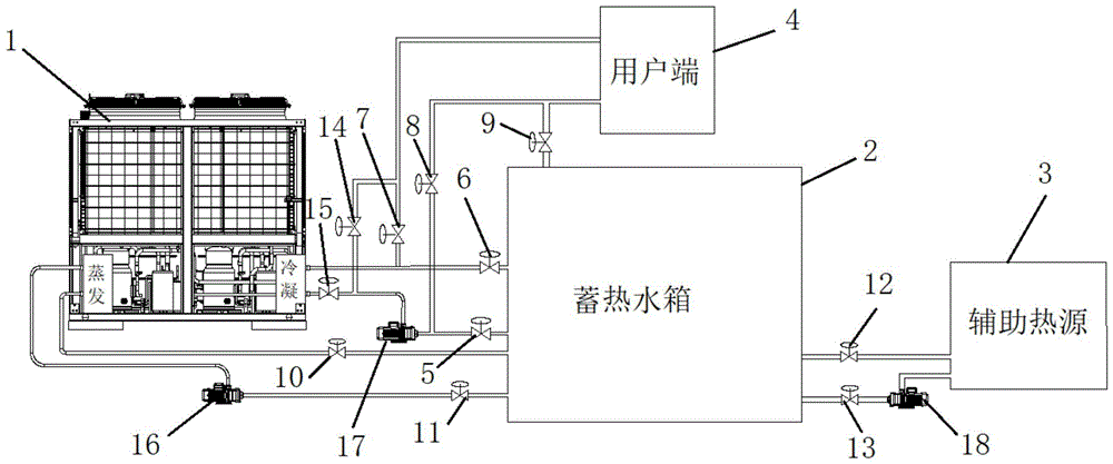
Double-source heat pump heating system
Technical Field
The invention relates to the technical field of heat pump heat supply, in particular to a double-source heat pump heat supply system.
Background
The heat pump technology is a technology for flowing heat from a low-level heat source to a high-level heat source under the push of high-level energy. That is, the heat source of low grade, such as air, soil, water, solar energy, industrial waste heat, etc., which can not be directly utilized, is converted into the available high-grade energy heat source, thereby achieving the technology of partially saving the disposable energy.
The dual-source heat pump is different from the common heat pump in that the same unit can use a water source and an air source as a heat source. When a double-source heat pump in the prior art works, heat collected by solar energy is stored by a heat storage device to be used as water source heat energy, and when the solar energy is insufficient, the heat is converted into heat collected by air. As shown in fig. 1, heat energy of heat sources such as solar energy is recovered to an energy storage water tank, the energy storage water tank is connected with an evaporation end of a heat pump host to heat the heat pump host, and a condensation end of the heat pump host supplies heat to a user end. The heat pump can be ensured to always operate in a higher-efficiency interval through automatic switching of the heat source of the heat pump main machine, and the purposes of high efficiency and energy conservation are achieved. However, the amount of heat required by the user side in the daytime is far greater than that required at night, and the heat pump can only adjust the operation efficiency through the input end during operation, so that the heat energy obtained from the heat pump is insufficient in the energy consumption peak period of the user side, and the output power of the heat pump is far greater than the requirement of the user side in the energy consumption valley period of the user side, thereby causing energy waste.
Disclosure of Invention
Therefore, the technical problem to be solved by the invention is to overcome the defects that the output power of the dual-source heat pump system in the prior art is insufficient in the peak period of energy utilization and excessive in the valley period of energy utilization, which causes energy waste, thereby providing a dual-source heat pump heating system.
In order to solve the technical effects, the invention provides a double-source heat pump heating system, which comprises:
the evaporator end of the heat pump host is communicated with the energy storage equipment in a circulating mode, and the condenser end of the heat pump host is communicated with the user end through a second circulating pipeline;
the auxiliary heat source is circularly communicated with the energy storage equipment;
and the energy storage circulating pipeline is communicated with the second circulating pipeline in parallel, and the energy storage equipment is arranged in the energy storage circulating pipeline.
Optionally, the second circulation pipeline comprises a second output pipe and a second return pipe, and the second output pipe and the second return pipe are both communicated between the user side and the condenser end of the heat pump host;
the energy storage circulating pipeline comprises an energy storage input pipe and an energy storage return pipe, one end of the energy storage input pipe is communicated with the second output pipe, the other end of the energy storage input pipe is communicated with the energy storage equipment, one end of the energy storage return pipe is communicated with the second return pipe, and the other end of the energy storage return pipe is communicated with the energy storage equipment.
Optionally, the system further comprises an energy storage and heat supply pipe, wherein one end of the energy storage and heat supply pipe is communicated with the user side, and the other end of the energy storage and heat supply pipe is communicated with the energy storage equipment.
Optionally, a second pump body is mounted on the second output pipe, and the energy storage input pipe is communicated with the second output pipe at the outlet end of the second pump body.
Optionally, the pump further comprises an auxiliary branch, one end of the auxiliary branch is communicated with the second return pipe, and the other end of the auxiliary branch is communicated with a second output pipe at the inlet end of the second pump body.
Optionally, the evaporator end of the heat pump host is in circulating communication with the energy storage device through a first circulating pipeline, the first circulating pipeline includes a first output pipe and a first return pipe, and the first output pipe and the first return pipe are both communicated between the energy storage device and the evaporator end of the heat pump host.
Optionally, a first pump body is mounted on the first output pipe.
Optionally, the auxiliary heat source is in circulating communication with the energy storage device through an auxiliary heat circulation pipeline, the auxiliary heat circulation pipeline comprises an auxiliary heat input pipe and an auxiliary heat return pipe, and the auxiliary heat input pipe and the auxiliary heat return pipe are both communicated between the energy storage device and the auxiliary heat source.
Optionally, a third pump body is mounted on the auxiliary heat input pipe.
Optionally, the energy storage device is an energy storage tank.
The technical scheme of the invention has the following advantages:
1. the invention provides a double-source heat pump heating system, which comprises: the evaporator end of the heat pump host is communicated with the energy storage equipment in a circulating mode, and the condenser end of the heat pump host is communicated with the user end through a second circulating pipeline; the auxiliary heat source is circularly communicated with the energy storage equipment; and the energy storage circulating pipeline is communicated with the second circulating pipeline in parallel, and the energy storage equipment is arranged in the energy storage circulating pipeline.
In the working process of the double-source heat pump heating system, the heat pump host can directly supply heat to the user side through the second circulation pipeline, and can also heat and raise the temperature of the energy storage equipment through the energy storage circulation pipeline connected in parallel on the second circulation pipeline, so that energy is stored in the energy storage equipment. The energy storage equipment is communicated with the top end of the user through the energy storage circulation pipeline and the second circulation pipeline, so that the energy storage equipment can directly supply heat to the user side. The energy consumption peak period of the user side is used, the heat pump and the energy storage equipment are used for supplying heat to the user side at the same time, the heat pump or the energy storage equipment is used for independently supplying heat to the user side at the energy consumption valley period, and redundant heat is stored in the energy storage equipment through the heat pump. The double-source heat pump heating system does not need to be additionally provided with an energy storage device, the output mode of the double-source heat pump heating system is adjusted according to the heat utilization requirement of a user side while the double-source heat pump heating system operates in a higher-efficiency interval only by adding an energy storage circulating pipeline, and redundant heat can be stored in energy storage equipment for use in an energy utilization peak period. The defects that the output power of the heat pump unit is insufficient in the energy consumption peak period and the output power is excessive in the energy consumption valley period are effectively overcome, the heat can be fully utilized, and the energy waste of the double-source heat pump heating system is reduced.
2. The invention provides a double-source heat pump heating system which further comprises an energy storage heating pipe, wherein one end of the energy storage heating pipe is communicated with a user side, and the other end of the energy storage heating pipe is communicated with energy storage equipment. Through setting up the energy storage heat supply pipe, communicate energy storage equipment is direct with the user, when direct heat supply to the user through energy storage equipment, energy storage equipment can be directly through the energy storage heat supply pipe to provide heat energy to the user, can shorten the pipeline length between energy storage equipment and the user, reduces the loss of heat energy in the pipeline data send process.
3. The double-source heat pump heating system further comprises an auxiliary branch, wherein one end of the auxiliary branch is communicated with the second return pipe, and the other end of the auxiliary branch is communicated with a second output pipe at the inlet end of the second pump body. Through supplementary branch road with second back flow and second output tube intercommunication, can not pass through the condenser end of heat pump host computer when energy storage equipment supplies heat to the user side, only supply heat or supply heat to the user side through the condenser end series connection of energy storage equipment and heat pump host computer to the user side alone through energy storage equipment for double-source heat pump heating system can be according to the user side needs, adjusts multiple operational mode.
4. The invention provides a double-source heat pump heating system. Through setting up the first pump body for heat energy in the energy storage equipment can initiatively flow in the evaporimeter end of heat pump host computer, can realize the frost removal of heat pump host computer and prevent frostbite the function.
Drawings
In order to more clearly illustrate the embodiments of the present invention or the technical solutions in the prior art, the drawings used in the description of the embodiments or the prior art will be briefly described below, and it is obvious that the drawings in the following description are some embodiments of the present invention, and other drawings can be obtained by those skilled in the art without creative efforts.
Fig. 1 is a schematic diagram of a heating system of a dual-source heat pump in the prior art.
Fig. 2 is a schematic diagram of a dual-source heat pump heating system provided in an embodiment of the present invention.
Fig. 3 is a schematic diagram of a dual-source heat pump heating system according to another embodiment of the present invention.
Description of the reference numerals: 1. a heat pump host; 2. an energy storage water tank; 3. an auxiliary heat source; 4. a user side; 5. a first valve; 6. a second valve; 7. a third valve; 8. a fourth valve; 9. a fifth valve; 10. a sixth valve; 11. a seventh valve; 12. an eighth valve; 13. a ninth valve; 14. a tenth valve; 15. an eleventh valve; 16. a first pump body; 17. a second pump body; 18. and a third pump body.
Detailed Description
The technical solutions of the present invention will be described clearly and completely with reference to the accompanying drawings, and it is to be understood that the described embodiments are only a part of the embodiments of the present invention, and not all of the embodiments. All other embodiments, which can be obtained by a person skilled in the art without making any creative effort based on the embodiments in the present invention, belong to the protection scope of the present invention.
In the description of the present invention, it should be noted that the terms "center", "upper", "lower", "left", "right", "vertical", "horizontal", "inner", "outer", etc., indicate orientations or positional relationships based on the orientations or positional relationships shown in the drawings, and are only for convenience of description and simplicity of description, but do not indicate or imply that the device or element being referred to must have a particular orientation, be constructed and operated in a particular orientation, and thus, should not be construed as limiting the present invention. Furthermore, the terms "first," "second," and "third" are used for descriptive purposes only and are not to be construed as indicating or implying relative importance.
In the description of the present invention, it should be noted that, unless otherwise explicitly specified or limited, the terms "mounted," "connected," and "connected" are to be construed broadly, e.g., as meaning either a fixed connection, a removable connection, or an integral connection; can be mechanically or electrically connected; they may be connected directly or indirectly through intervening media, or they may be interconnected between two elements. The specific meanings of the above terms in the present invention can be understood in a specific case to those of ordinary skill in the art.
Furthermore, the technical features involved in the different embodiments of the present invention described below may be combined with each other as long as they do not conflict with each other.
Examples
As shown in fig. 2, the dual-source heat pump heating system provided in this embodiment includes: a heat pump host 1, an auxiliary heat source 3 and energy storage equipment. In this embodiment, the energy storage device is an energy storage water tank 2, and the auxiliary heat source 3 is a heat source such as solar energy and power plant waste heat. The energy storage equipment can also be a reversible phase change heat storage device and other devices capable of storing heat in large capacity.
The evaporator end of the heat pump host 1 is in circulating communication with the energy storage water tank 2, and the condenser end of the heat pump host 1 is communicated with the user end 4 through a second circulating pipeline; the auxiliary heat source 3 is circularly communicated with the energy storage water tank 2; and the energy storage circulating pipeline is communicated with the second circulating pipeline in parallel, and the energy storage water tank 2 is arranged in the energy storage circulating pipeline.
The second circulation pipeline comprises a second output pipe and a second return pipe, and the second output pipe and the second return pipe are both communicated between the user side 4 and the condenser end of the heat pump host 1; the energy storage circulating pipeline comprises an energy storage input pipe and an energy storage return pipe, one end of the energy storage input pipe is communicated with the second output pipe, the other end of the energy storage input pipe is communicated with the energy storage water tank 2, one end of the energy storage return pipe is communicated with the second return pipe, and the other end of the energy storage return pipe is communicated with the energy storage water tank 2. And an energy storage and heat supply pipe is directly communicated between the user terminal 4 and the energy storage water tank 2, one end of the energy storage and heat supply pipe is directly communicated with the energy storage water tank 2 in the embodiment, and the other end of the energy storage and heat supply pipe is communicated with one end, close to the user terminal 4, of the second output pipe. And a second pump body 17 is arranged on the second output pipe, and the energy storage input pipe is communicated with the second output pipe at the outlet end of the second pump body 17.
The evaporator end of the heat pump host 1 is in circulating communication with the energy storage water tank 2 through a first circulating pipeline, the first circulating pipeline comprises a first output pipe and a first return pipe, and the first output pipe and the first return pipe are both communicated between the energy storage water tank 2 and the evaporator end of the heat pump host 1. A first pump body 16 is mounted on the first outlet conduit.
The auxiliary heat source 3 is in circulating communication with the energy storage water tank 2 through an auxiliary heat circulating pipeline, the auxiliary heat circulating pipeline comprises an auxiliary heat input pipe and an auxiliary heat return pipe, and the auxiliary heat input pipe and the auxiliary heat return pipe are both communicated between the energy storage water tank 2 and the auxiliary heat source 3. The third pump body 18 is arranged on the auxiliary heat input pipe, and the third pump body 18 works to recover the heat energy in the auxiliary heat source 3 into the energy storage water tank 2 to heat the energy storage water tank 2.
In this embodiment, the energy storage input pipe is provided with a first valve 5. The energy storage return pipe is provided with a second valve 6. A third valve 7 is arranged on the second return pipe, and the energy storage return pipe is connected to the second return pipe between the third valve 7 and the heat pump host 1. A fourth valve 8 is arranged on the second output pipe, and the energy storage input pipe is communicated with the second output pipe between the fourth valve 8 and the second pump body 17. And a fifth valve 9 is arranged on the energy storage and heat supply pipe, and the energy storage and heat supply pipe is communicated with a second output pipe between the fourth valve 8 and the user terminal 4. A sixth valve 10 is mounted on the first return line, and a seventh valve 11 is mounted on the first output line between the first pump body 16 and the energy storage device. An eighth valve 12 is arranged on the auxiliary heat loop pipe, and a ninth valve 13 is arranged between the third pump body 18 and the energy storage water tank 2 on the auxiliary heat input pipe.
In the operation process of the dual-source heat pump heating system provided in this embodiment, when the first valve 5, the second valve 6, and the fifth valve 9 are closed and the third valve 7 and the fourth valve 8 are opened, the host directly supplies heat to the user terminal 4. The third valve 7, the fourth valve 8 and the fifth valve 9 are closed, when the first valve 5 and the second valve 6 are opened, the heat pump host 1 heats the energy storage water tank 2, and redundant heat is stored in the energy storage water tank 2 and used for storing heat in the valley period. The second valve 6 and the fourth valve 8 are closed, and the energy storage water tank 2 supplies heat to the end when the first valve 5, the third valve 7 and the fifth valve 9 are opened. In the energy consumption peak period of the user terminal 4, the heat pump and the energy storage equipment are used for supplying heat to the user terminal 4 at the same time, in the energy consumption valley period, the heat pump or the energy storage equipment is used for independently supplying heat to the user terminal 4, and redundant heat is stored in the energy storage equipment through the heat pump. The double-source heat pump heating system does not need to be additionally provided with an energy storage device or an additional device cost, the output mode of the double-source heat pump heating system is adjusted according to the heat utilization requirement of the user terminal 4 while the double-source heat pump heating system operates in a higher-efficiency interval only by adding an energy storage circulating pipeline, and redundant heat can be stored in the energy storage device so as to be used in the energy utilization peak period. The defects that the output power of the heat pump unit is insufficient in the energy consumption peak period and excessive in the energy consumption valley period are effectively overcome, the heat can be fully utilized, the energy waste of the double-source heat pump heating system is reduced, and the energy storage is realized by utilizing the heat consumption peak valley, so that the real energy-saving and money-saving effects are achieved for users.
As an alternative embodiment, as shown in fig. 3, in order to enable the heat pump heating system to switch to more different heating modes, an auxiliary branch is further included in the heat pump heating system, one end of the auxiliary branch is connected to the second return pipe between the third valve 7 and the user terminal 4, the other end of the auxiliary branch is connected to the second output pipe at the inlet end of the second pump body 17, a tenth valve 14 is installed on the auxiliary branch, and an eleventh valve 15 is installed on the second output pipe between the heat pump main unit 1 and the auxiliary branch. In the operation process of the dual-source heat pump heating system provided in this embodiment, when the first valve 5, the second valve 6, the fifth valve 9, and the tenth valve 14 are closed, and the third valve 7, the fourth valve 8, and the eleventh valve 15 are opened, the heat pump host 1 directly supplies heat to the user terminal 4. And when the third valve 7, the fourth valve 8, the fifth valve 9 and the tenth valve 14 are closed and the first valve 5, the second valve 6 and the eleventh valve 15 are opened, the heat pump host 1 directly supplies heat to the energy storage water tank 2. The second valve 6, the third valve 7, the fourth valve 8 and the eleventh valve 15 are closed, and when the first valve 5, the fifth valve 9 and the tenth valve 14 are opened, the energy storage water tank 2 directly supplies heat to the user terminal 4.
It should be understood that the above examples are only for clarity of illustration and are not intended to limit the embodiments. Other variations and modifications will be apparent to persons skilled in the art in light of the above description. This need not be, nor should it be exhaustive of all embodiments. And obvious variations or modifications derived therefrom are intended to be within the scope of the invention.