CN114751163A - A new type of speed-regulating metering conveyor belt - Google Patents
A new type of speed-regulating metering conveyor belt Download PDFInfo
- Publication number
- CN114751163A CN114751163A CN202210594142.XA CN202210594142A CN114751163A CN 114751163 A CN114751163 A CN 114751163A CN 202210594142 A CN202210594142 A CN 202210594142A CN 114751163 A CN114751163 A CN 114751163A
- Authority
- CN
- China
- Prior art keywords
- fixedly connected
- frame
- clamp
- blanking
- speed
- Prior art date
- Legal status (The legal status is an assumption and is not a legal conclusion. Google has not performed a legal analysis and makes no representation as to the accuracy of the status listed.)
- Pending
Links
Images


Classifications
-
- B—PERFORMING OPERATIONS; TRANSPORTING
- B65—CONVEYING; PACKING; STORING; HANDLING THIN OR FILAMENTARY MATERIAL
- B65G—TRANSPORT OR STORAGE DEVICES, e.g. CONVEYORS FOR LOADING OR TIPPING, SHOP CONVEYOR SYSTEMS OR PNEUMATIC TUBE CONVEYORS
- B65G47/00—Article or material-handling devices associated with conveyors; Methods employing such devices
- B65G47/02—Devices for feeding articles or materials to conveyors
- B65G47/16—Devices for feeding articles or materials to conveyors for feeding materials in bulk
- B65G47/18—Arrangements or applications of hoppers or chutes
- B65G47/19—Arrangements or applications of hoppers or chutes having means for controlling material flow, e.g. to prevent overloading
-
- B—PERFORMING OPERATIONS; TRANSPORTING
- B65—CONVEYING; PACKING; STORING; HANDLING THIN OR FILAMENTARY MATERIAL
- B65G—TRANSPORT OR STORAGE DEVICES, e.g. CONVEYORS FOR LOADING OR TIPPING, SHOP CONVEYOR SYSTEMS OR PNEUMATIC TUBE CONVEYORS
- B65G43/00—Control devices, e.g. for safety, warning or fault-correcting
-
- B—PERFORMING OPERATIONS; TRANSPORTING
- B65—CONVEYING; PACKING; STORING; HANDLING THIN OR FILAMENTARY MATERIAL
- B65G—TRANSPORT OR STORAGE DEVICES, e.g. CONVEYORS FOR LOADING OR TIPPING, SHOP CONVEYOR SYSTEMS OR PNEUMATIC TUBE CONVEYORS
- B65G69/00—Auxiliary measures taken, or devices used, in connection with loading or unloading
- B65G69/12—Sieving bulk materials during loading or unloading
-
- B—PERFORMING OPERATIONS; TRANSPORTING
- B65—CONVEYING; PACKING; STORING; HANDLING THIN OR FILAMENTARY MATERIAL
- B65G—TRANSPORT OR STORAGE DEVICES, e.g. CONVEYORS FOR LOADING OR TIPPING, SHOP CONVEYOR SYSTEMS OR PNEUMATIC TUBE CONVEYORS
- B65G2203/00—Indexing code relating to control or detection of the articles or the load carriers during conveying
- B65G2203/02—Control or detection
- B65G2203/0266—Control or detection relating to the load carrier(s)
- B65G2203/0291—Speed of the load carrier
Landscapes
- Engineering & Computer Science (AREA)
- Mechanical Engineering (AREA)
- Filling Or Emptying Of Bunkers, Hoppers, And Tanks (AREA)
Abstract
本发明公开了一种新型调速计量输送带,涉及下料技术领域,包括框架,框架底部焊接有支架,支架上通过调速组件与传动组件连接有履带,还包括下料控制机构,所述下料控制机构包括安装组件、储料组件、下料管与下料控制组件,所述储料组件通过安装组件连接在框架上方,所述下料管分为上下两段,上段所述下料管顶端固定连接在储料组件上,所述下料控制组件包括卡箍,上段所述下料管与下段下料管通过卡箍相连接,所述卡箍右端固定连接有伸缩装置,相对于现有技术,本发明制造成本低,与此同时下料速度可调,便于计量,结构简单,便于更换维修。
The invention discloses a novel speed-adjusting metering conveyor belt, which relates to the technical field of blanking. The blanking control mechanism includes an installation component, a storage component, a blanking pipe and a blanking control component. The storage component is connected to the top of the frame through the installation component. The blanking pipe is divided into upper and lower sections. The top of the pipe is fixedly connected to the material storage assembly, the feeding control assembly includes a clamp, the feeding pipe in the upper section is connected with the feeding pipe in the lower section through the clamp, and the right end of the clamp is fixedly connected with a telescopic device, which is relatively In the prior art, the present invention has low manufacturing cost, and at the same time, the feeding speed is adjustable, which is convenient for metering, simple in structure, and convenient for replacement and maintenance.
Description
技术领域technical field
本发明涉及下料技术领域,具体为一种新型调速计量输送带。The invention relates to the technical field of blanking, in particular to a novel speed-adjusting metering conveyor belt.
背景技术Background technique
输送带,又称运输带,是用于皮带输送带中起承载和运送物料作用的橡胶与纤维、金属复合制品,或者是塑料和织物复合的制品,输送带广泛应用于水泥、焦化、冶金、化工、钢铁等行业中输送距离较短、输送量较小的场合。Conveyor belts, also known as conveyor belts, are rubber and fiber, metal composite products, or plastic and fabric composite products that are used in belt conveyor belts to carry and transport materials. Conveyor belts are widely used in cement, coking, metallurgy, In chemical, steel and other industries where the conveying distance is short and the conveying volume is small.
现有的配合输送带的物料下料方式是通过喂料机控制料斗下料,这种方式虽然可以做到下料均匀,但是其制造成本高,机械故障概率大,使用成本高,结构复杂,体积大,而且料仓过大时,所需的喂料机较大,与之配套的料斗也较大,无形中会造成料仓高度的增加,大大增加土建成本,因此需要研发一种新型调速计量输送带。The existing material unloading method with the conveyor belt is to control the hopper unloading through the feeder. Although this method can achieve uniform unloading, it has high manufacturing cost, high probability of mechanical failure, high use cost and complex structure. The volume is large, and when the silo is too large, the required feeder is larger, and the matching hopper is also larger, which will invisibly increase the height of the silo and greatly increase the cost of civil construction. Therefore, it is necessary to develop a new type of adjustment. Speed metering conveyor belt.
发明内容SUMMARY OF THE INVENTION
本发明的目的在于提供一种新型调速计量输送带,以解决上述背景技术中提出的现有的配合输送带的物料下料方式是通过喂料机控制料斗下料,这种方式虽然可以做到下料均匀,但是其制造成本高,机械故障概率大,使用成本高,结构复杂,体积大,而且料仓过大时,所需的喂料机较大,与之配套的料斗也较大,无形中会造成料仓高度的增加,大大增加土建成本的问题。The purpose of the present invention is to provide a new type of speed-adjusting metering conveyor belt, in order to solve the problem that the existing method of material unloading with the conveyor belt proposed in the above-mentioned background technology is to control the hopper unloading through the feeder, although this method can be done The material is evenly cut, but its manufacturing cost is high, the probability of mechanical failure is high, the use cost is high, the structure is complex, the volume is large, and when the silo is too large, the required feeder is larger, and the matching hopper is also larger. , which will virtually increase the height of the silo and greatly increase the cost of civil construction.
为实现上述目的,本发明提供如下技术方案:一种新型调速计量输送带,包括框架,框架底部焊接有支架,支架上通过调速组件与传动组件连接有履带,还包括下料控制机构;In order to achieve the above purpose, the present invention provides the following technical solutions: a novel speed-adjusting metering conveyor belt, comprising a frame, a bracket welded to the bottom of the frame, a crawler belt connected to the transmission assembly through a speed-adjusting assembly, and a blanking control mechanism;
所述下料控制机构包括安装组件、储料组件、下料管与下料控制组件,所述储料组件通过安装组件连接在框架上方,所述下料管分为上下两段,上段所述下料管顶端固定连接在储料组件上,所述下料控制组件包括卡箍,上段所述下料管与下段下料管通过卡箍相连接,所述卡箍右端固定连接有伸缩装置,所述伸缩装置输出端贯穿卡箍右端,且伸缩装置输出端固定连接有连接扣,所述连接扣上固定连接有门板,所述门板左端插设在上段下料管与下段下料管之间,所述连接扣底部固定连接有连接块,所述连接块上通过第一钢丝绳连接有转杆,所述转杆右端转动连接在卡箍右端底部,所述转杆左端固定连接有可调节门,所述可调节门左端顶部固定连接有第二钢丝绳,所述第二钢丝绳顶端固定连接在卡箍左端底部,下段所述下料管位于可调节门内部。The blanking control mechanism includes an installation component, a material storage component, a blanking pipe and a blanking control component, the storage component is connected above the frame through the installation component, and the blanking pipe is divided into upper and lower sections. The top of the feeding pipe is fixedly connected to the material storage assembly, the feeding control assembly includes a clamp, the feeding pipe in the upper section and the feeding pipe in the lower section are connected by a clamp, and a telescopic device is fixedly connected to the right end of the clamp. The output end of the expansion device runs through the right end of the clamp, and the output end of the expansion device is fixedly connected with a connection buckle, the connection buckle is fixedly connected with a door plate, and the left end of the door plate is inserted between the upper section feeding pipe and the lower section feeding pipe , a connecting block is fixedly connected to the bottom of the connecting buckle, a rotating rod is connected to the connecting block through a first wire rope, the right end of the rotating rod is rotatably connected to the bottom of the right end of the clamp, and the left end of the rotating rod is fixedly connected with an adjustable door The top of the left end of the adjustable door is fixedly connected with a second steel wire rope, the top of the second steel wire rope is fixedly connected to the bottom of the left end of the clamp, and the lower section of the feeding pipe is located inside the adjustable door.
优选的,所述调速组件包括变频电机,所述变频电机固定连接在框架右端的后表面,所述传动组件与变频电机输出端固定连接。Preferably, the speed control assembly includes a frequency conversion motor, the frequency conversion motor is fixedly connected to the rear surface of the right end of the frame, and the transmission assembly is fixedly connected to the output end of the frequency conversion motor.
优选的,所述传动组件包括传动辊,所述传动辊数量为两个,两个所述传动辊分别转动连接在框架的左右两端,转动连接在框架右端的所述传动辊后端与变频电机输出端固定连接,所述履带缠绕在两个传动辊之间,所述框架上表面前后对称设有多个辊筒安装架,多个所述辊筒安装架上均转动连接有辊筒,所述履带表面与多个辊筒表面相贴合。Preferably, the transmission assembly includes transmission rollers, and the number of the transmission rollers is two, the two transmission rollers are respectively connected to the left and right ends of the frame, and the rear end of the transmission roller connected to the right end of the frame and the frequency conversion The output end of the motor is fixedly connected, the crawler is wound between the two drive rollers, the upper surface of the frame is symmetrically provided with a plurality of roller mounting frames, and the rollers are rotatably connected to the plurality of the roller mounting frames. The track surface is in contact with a plurality of roller surfaces.
优选的,所述安装组件包括直角弯板,所述直角弯板数量为多个,多个所述直角弯板的底端均固定连接在框架上表面,所述储料组件通过直角弯板固定在框架的上方。Preferably, the installation assembly includes a right-angle bent plate, the number of the right-angle bent plate is multiple, the bottom ends of the right-angle bent plates are all fixedly connected to the upper surface of the frame, and the material storage assembly is fixed by the right-angle bent plate above the frame.
优选的,所述储料组件包括料斗,所述料斗数量与直角弯板数量相等,所述料斗固定连接在直角弯板顶端,多个所述料斗均位于框架的上方,上段所述下料管顶端固定连接在料斗底端。Preferably, the storage assembly includes a hopper, the number of the hopper is equal to the number of the right-angle bent plate, the hopper is fixedly connected to the top of the right-angle bent plate, a plurality of the hoppers are located above the frame, and the upper section of the feeding pipe The top end is fixedly connected to the bottom end of the hopper.
优选的,多个所述料斗顶端均嵌有筛网。Preferably, screens are embedded in the tops of a plurality of the hoppers.
优选的,所述伸缩装置为气动伸缩杆。Preferably, the telescopic device is a pneumatic telescopic rod.
优选的,所述伸缩装置为电动伸缩杆。Preferably, the telescopic device is an electric telescopic rod.
与现有技术相比,本发明的有益效果是:Compared with the prior art, the beneficial effects of the present invention are:
1.通过设有的调速输送机构的配合使用,使得履带可直接由变频电机控制带速,从而使得本发明达到调速输送的效果,通过设有的下料控制机构的配合使用,可由伸缩装置控制门板的左右移动以及移动距离,从而控制下料管是否开口以及开口大小,使得料斗中物料的下料速度和流量得到控制,相对于现有技术,本发明制造成本低,与此同时下料速度可调,便于计量,结构简单,便于更换维修;1. Through the coordinated use of the provided speed-adjusting conveying mechanism, the crawler belt can be directly controlled by the frequency conversion motor, so that the present invention can achieve the effect of speed-adjusting conveying. The device controls the left and right movement and the moving distance of the door panel, so as to control whether the feeding pipe is open or not and the size of the opening, so that the feeding speed and flow of the material in the hopper can be controlled. The material speed is adjustable, easy to measure, the structure is simple, easy to replace and maintain;
2.通过可调节门的上下运动,可以对物料下料时的高度进行限位,避免物料溢出;2. Through the up and down movement of the adjustable door, the height of the material can be limited to avoid material overflow;
3.多个取料点的设计使得料仓的下料分布更均匀,从而避免了取料点过少导致的下料死角,造成物料浪费,同时适用于较大的料仓。3. The design of multiple reclaiming points makes the material distribution of the silo more uniform, thus avoiding the blanking dead angle caused by too few reclaiming points, resulting in material waste, and it is suitable for larger silos at the same time.
附图说明Description of drawings
图1为本发明的三维结构示意图;Fig. 1 is the three-dimensional structure schematic diagram of the present invention;
图2为本发明的结构主视图;Fig. 2 is the structural front view of the present invention;
图3为本发明的结构俯视图;Fig. 3 is the structure top view of the present invention;
图4为本发明中下料控制机构的结构剖视图;Fig. 4 is the structural sectional view of the blanking control mechanism in the present invention;
图5为本发明中下料控制机构的三维结构示意图;Fig. 5 is the three-dimensional structure schematic diagram of the blanking control mechanism in the present invention;
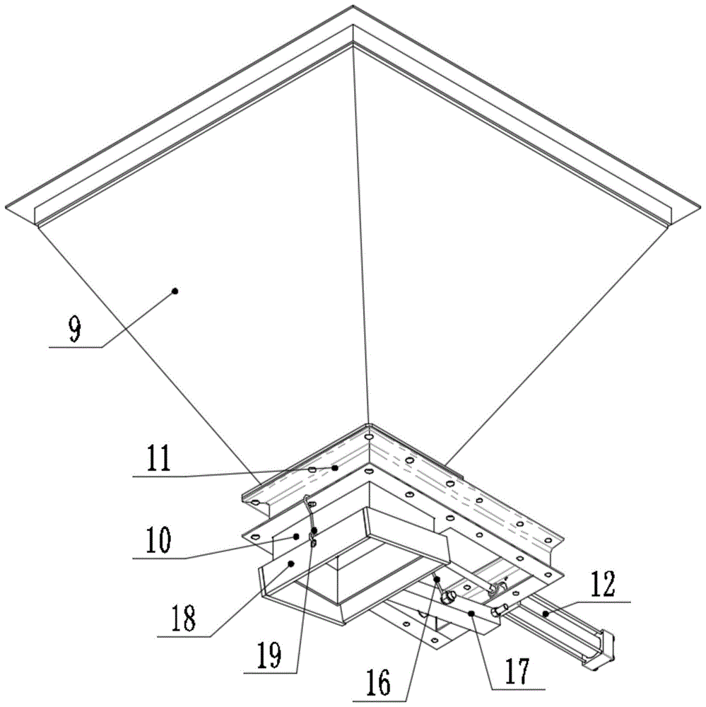
图6为本发明中下料控制机构的三维结构示意图。FIG. 6 is a three-dimensional structural schematic diagram of the blanking control mechanism in the present invention.
图中:1、框架;2、支架;3、变频电机;4、传动辊;5、履带;6、辊筒安装架;7、辊筒;8、直角弯板;9、料斗;10、下料管;11、卡箍;12、伸缩装置;13、连接扣;14、门板;15、连接块;16、第一钢丝绳;17、转杆;18、可调节门;19、第二钢丝绳;20、筛网。In the figure: 1. Frame; 2. Bracket; 3. Frequency conversion motor; 4. Drive roller; 5. Track; 6. Roller mounting frame; 7. Roller; 8. Right-angle bending plate; 9. Hopper; 10. Bottom Material pipe; 11, clamp; 12, telescopic device; 13, connecting buckle; 14, door panel; 15, connecting block; 16, first wire rope; 17, rotating rod; 18, adjustable door; 19, second wire rope; 20. Screen.
具体实施方式Detailed ways
下面将结合本发明实施例中的附图,对本发明实施例中的技术方案进行清楚、完整地描述,显然,所描述的实施例仅仅是本发明一部分实施例,而不是全部的实施例。基于本发明中的实施例,本领域普通技术人员在没有做出创造性劳动前提下所获得的所有其他实施例,都属于本发明保护的范围。The technical solutions in the embodiments of the present invention will be clearly and completely described below with reference to the accompanying drawings in the embodiments of the present invention. Obviously, the described embodiments are only a part of the embodiments of the present invention, but not all of the embodiments. Based on the embodiments of the present invention, all other embodiments obtained by those of ordinary skill in the art without creative efforts shall fall within the protection scope of the present invention.
本发明提供如下技术方案:The present invention provides the following technical solutions:
实施例一:Example 1:
请参阅图1-6,一种新型调速计量输送带,包括框架1,框架1底部焊接有支架2,支架2上通过调速组件与传动组件连接有履带5,调速组件包括变频电机3,变频电机3固定连接在框架1右端的后表面,传动组件与变频电机3输出端固定连接,传动组件包括传动辊4,传动辊4数量为两个,两个传动辊4分别转动连接在框架1的左右两端,转动连接在框架1右端的传动辊4后端与变频电机3输出端固定连接,所以当变频电机3做功时,能够带动传动辊4转动,且变频电机3通过改变电量能够改变转速,从而达到调速效果,履带5缠绕在两个传动辊4之间,所以当变频电机3带动传动辊4转动时,能够带动履带5转动,从而达到调速输送物料的效果,框架1上表面前后对称设有多个辊筒安装架6,多个辊筒安装架6上均转动连接有辊筒7,履带5表面与多个辊筒7表面相贴合,多个辊筒7可用于支撑履带5,还包括下料控制机构;Please refer to Figure 1-6, a new type of speed-adjustable metering conveyor belt, including a
下料控制机构包括安装组件、储料组件、下料管10与下料控制组件,储料组件通过安装组件连接在框架1上方,下料管10分为上下两段,上段下料管10顶端固定连接在储料组件上,下料控制组件包括卡箍11,上段下料管10与下段下料管10通过卡箍11相连接,卡箍11右端固定连接有伸缩装置12,伸缩装置12输出端贯穿卡箍11右端,且伸缩装置12输出端固定连接有连接扣13,连接扣13上固定连接有门板14,所以当伸缩装置12做功时,能够通过连接扣13带动门板14左右移动,门板14左端插设在上段下料管10与下段下料管10之间,所以当伸缩装置12做功带动门板14左右移动时,能够控制门板14在两段下料管10之间移动,当门板14左端移动到最左端时,两段下料管10之间不连通,即可起到堵料的效果,当门板14左端移动到最右端时,两段下料管10之间全部连通,即可达到最大流量下料的效果,所以本发明可通过由伸缩装置12控制门板14的左右移动以及移动距离,从而控制下料管10是否开口以及开口大小,从而使得物料的下料速度和流量得到控制,连接扣13底部固定连接有连接块15,连接块15上通过第一钢丝绳16连接有转杆17,转杆17右端转动连接在卡箍11右端底部,转杆17左端固定连接有可调节门18,所以当伸缩装置12带动门板14移动到最左端时,即下料管10不在下料时,可通过第一钢丝绳16将转杆17拉起,从而将可调节门18拉起,当伸缩装置12带动门板14右移到最左端时,即下料管10在下料过程中,第一钢丝绳16处于松弛状态,不再对转杆17提供拉力,此时可调节门18在重力的作用下下移,从而可以对物料下料时的高度进行限位,避免物料溢出,可调节门18左端顶部固定连接有第二钢丝绳19,第二钢丝绳19顶端固定连接在卡箍11左端底部,下段下料管10位于可调节门18内部,所以在第二钢丝绳19的作用下,可起到吊装可调节门18的作用,使得本发明结构设计合理;The blanking control mechanism includes an installation component, a storage component, a blanking
安装组件包括直角弯板8,直角弯板8数量为多个,多个直角弯板8的底端均固定连接在框架1上表面,储料组件通过直角弯板8固定在框架1的上方,储料组件包括料斗9,料斗9数量与直角弯板8数量相等,料斗9固定连接在直角弯板8顶端,多个料斗9均位于框架1的上方,所以工作人员可将所需控制下料速度和流量的物料加入到料斗9中,上段下料管10顶端固定连接在料斗9底端,所以加入到料斗9中的物料能够在重力的作用下由下料管10下料;The installation assembly includes a right-angle
多个料斗9顶端均嵌有筛网20,可用于筛选出物料中堆积成的体积较大的块状物料,保证进入到料斗9中的物料大小均匀,从而有效降低物料由下料管10下料时出现堵料的概率;The tops of the
而且在多个料斗9的作用下,能够与料仓底部连接成多个取料点,从而避免了取料点过少导致的下料死角,有效防止料仓内的物料下料不充分,同时适用于较大的料仓。Moreover, under the action of
工作原理:工作人员可先将多个料斗9均连接在料仓的底部,形成多个取料点,此时所需控制下料速度和流量的物料会加入到多个料斗9中,所以在多个料斗9的作用下,能够与料仓底部连接成多个取料点,从而避免了取料点过少导致的下料死角,有效防止料仓内的物料下料不充分,同时适用于较大的料仓,此时在筛网20的作用下,能够筛选出物料中堆积成的体积较大的块状物料,保证进入到料斗9中的物料大小均匀,从而有效降低物料由下料管10下料时出现堵料的概率;Working principle: The staff can first connect
然后工作人员打开变频电机3,当变频电机3做功时,能够带动传动辊4转动,当变频电机3带动传动辊4转动时,能够带动履带5逆时针转动,且变频电机3自身能够通过改变电量改变转速,从而使得本发明达到调速输送物料的效果,然后工作人员先打开连接在料仓底部最右端的伸缩装置12,即先打开一个取料点,其打开顺序为从右到左依次打开,使得料仓内的物料依次下料,防止多个伸缩装置12同时打开,即多个取料点同时使用时,造成右侧取料点正常下料,左侧取料点因履带5上已经存在的物料堵塞而无法正常下料的问题,使得本发明结构设计合理;Then the staff turns on the
当每个伸缩装置12做功时,均能够通过连接扣13带动相对应的门板14左右移动,当伸缩装置12做功带动门板14左右移动时,能够控制门板14在两段下料管10之间移动,当门板14左端移动到最左端时,两段下料管10之间不连通,即可起到堵料的效果,当门板14左端移动到最右端时,两段下料管10之间全部连通,即可达到最大流量下料的效果,所以本发明可通过由伸缩装置12控制门板14的左右移动以及移动距离,从而控制下料管10是否开口以及开口大小,从而使得物料的下料速度和流量得到控制,所以相对于现有技术,本发明制造成本低,与此同时下料速度可调,便于计量,结构简单,便于更换维修;When each
当伸缩装置12带动门板14移动到最左端时,即下料管10不在下料时,可通过第一钢丝绳16将转杆17拉起,从而将可调节门18拉起,当伸缩装置12带动门板14右移到最左端时,即下料管10在下料过程中,第一钢丝绳16处于松弛状态,不再对转杆17提供拉力,此时可调节门18在重力的作用下下移,所以当下料到履带5上的物料随着履带5的逆时针转动而向左移动时,能够被落下的可调节门18刮平,从而可以对物料下料时的高度进行限位,避免物料溢出。When the
实施例二:Embodiment 2:
伸缩装置12为电动伸缩杆。The
工作原理:工作人员可先将多个料斗9均连接在料仓的底部,形成多个取料点,此时所需控制下料速度和流量的物料会加入到多个料斗9中,所以在多个料斗9的作用下,能够与料仓底部连接成多个取料点,从而避免了取料点过少导致的下料死角,有效防止料仓内的物料下料不充分,同时适用于较大的料仓,此时在筛网20的作用下,能够筛选出物料中堆积成的体积较大的块状物料,保证进入到料斗9中的物料大小均匀,从而有效降低物料由下料管10下料时出现堵料的概率;Working principle: The staff can first connect
然后工作人员打开变频电机3,当变频电机3做功时,能够带动传动辊4转动,当变频电机3带动传动辊4转动时,能够带动履带5逆时针转动,且变频电机3自身能够通过改变电量改变转速,从而使得本发明达到调速输送物料的效果,然后工作人员先打开连接在料仓底部最右端的伸缩装置12,即先打开一个取料点,其打开顺序为从右到左依次打开,使得料仓内的物料依次下料,防止多个伸缩装置12同时打开,即多个取料点同时使用时,造成右侧取料点正常下料,左侧取料点因履带5上已经存在的物料堵塞而无法正常下料的问题,使得本发明结构设计合理;Then the staff turns on the
当每个伸缩装置12做功时,均能够通过连接扣13带动相对应的门板14左右移动,当伸缩装置12做功带动门板14左右移动时,能够控制门板14在两段下料管10之间移动,当门板14左端移动到最左端时,两段下料管10之间不连通,即可起到堵料的效果,当门板14左端移动到最右端时,两段下料管10之间全部连通,即可达到最大流量下料的效果,所以本发明可通过由伸缩装置12控制门板14的左右移动以及移动距离,从而控制下料管10是否开口以及开口大小,从而使得物料的下料速度和流量得到控制,所以相对于现有技术,本发明制造成本低,与此同时下料速度可调,便于计量,结构简单,便于更换维修;When each
当伸缩装置12带动门板14移动到最左端时,即下料管10不在下料时,可通过第一钢丝绳16将转杆17拉起,从而将可调节门18拉起,当伸缩装置12带动门板14右移到最左端时,即下料管10在下料过程中,第一钢丝绳16处于松弛状态,不再对转杆17提供拉力,此时可调节门18在重力的作用下下移,所以当下料到履带5上的物料随着履带5的逆时针转动而向左移动时,能够被落下的可调节门18刮平,从而可以对物料下料时的高度进行限位,避免物料溢出。When the
虽然在上文中已经参考实施例对本发明进行了描述,然而在不脱离本发明的范围的情况下,可以对其进行各种改进并且可以用等效物替换其中的部件。尤其是,只要不存在结构冲突,本发明所披露的实施例中的各项特征均可通过任意方式相互结合起来使用,在本说明书中未对这些组合的情况进行穷举性的描述仅仅是出于省略篇幅和节约资源的考虑。因此,本发明并不局限于文中公开的特定实施例,而是包括落入权利要求的范围内的所有技术方案。Although the present invention has been described above with reference to the embodiments, various modifications may be made and equivalents may be substituted for parts thereof without departing from the scope of the invention. In particular, as long as there is no structural conflict, the various features in the disclosed embodiments of the present invention can be combined with each other in any way, and the description of these combinations is not exhaustive in this specification. For the sake of omitting space and saving resources. Therefore, the present invention is not limited to the specific embodiments disclosed herein, but includes all technical solutions falling within the scope of the claims.
Claims (8)
Priority Applications (1)
| Application Number | Priority Date | Filing Date | Title |
|---|---|---|---|
| CN202210594142.XA CN114751163A (en) | 2022-05-27 | 2022-05-27 | A new type of speed-regulating metering conveyor belt |
Applications Claiming Priority (1)
| Application Number | Priority Date | Filing Date | Title |
|---|---|---|---|
| CN202210594142.XA CN114751163A (en) | 2022-05-27 | 2022-05-27 | A new type of speed-regulating metering conveyor belt |
Publications (1)
| Publication Number | Publication Date |
|---|---|
| CN114751163A true CN114751163A (en) | 2022-07-15 |
Family
ID=82336236
Family Applications (1)
| Application Number | Title | Priority Date | Filing Date |
|---|---|---|---|
| CN202210594142.XA Pending CN114751163A (en) | 2022-05-27 | 2022-05-27 | A new type of speed-regulating metering conveyor belt |
Country Status (1)
| Country | Link |
|---|---|
| CN (1) | CN114751163A (en) |
Citations (8)
| Publication number | Priority date | Publication date | Assignee | Title |
|---|---|---|---|---|
| CN201907158U (en) * | 2010-12-20 | 2011-07-27 | 三一重工股份有限公司 | Concrete mixing plant and discharge hopper device |
| CN203855179U (en) * | 2014-04-30 | 2014-10-01 | 巩义市鸿达陶粒砂有限公司 | Automatic blending device in ceramsite sand production |
| CN205675747U (en) * | 2016-06-13 | 2016-11-09 | 希弗特科技(北京)有限公司 | A kind of Novel connected dynamic formula blanking mechanism |
| CN206679901U (en) * | 2017-03-24 | 2017-11-28 | 山东瀚邦胶带有限公司 | The big bag blanking proportioner of carbon black |
| CN207158229U (en) * | 2017-05-15 | 2018-03-30 | 湖北北新建材有限公司 | A kind of starch induction system and the plasterboard feed proportioning system including the system |
| CN212150587U (en) * | 2020-04-30 | 2020-12-15 | 曲靖市盛凯焦化有限责任公司 | Belt type quantitative coal feeding device |
| CN216376665U (en) * | 2021-10-21 | 2022-04-26 | 江西玖匠科技有限公司 | Even automatic loading attachment |
| CN218370214U (en) * | 2022-05-27 | 2023-01-24 | 四川瑞欣人杰企业管理有限责任公司 | Novel speed-regulating metering conveyer belt |
-
2022
- 2022-05-27 CN CN202210594142.XA patent/CN114751163A/en active Pending
Patent Citations (8)
| Publication number | Priority date | Publication date | Assignee | Title |
|---|---|---|---|---|
| CN201907158U (en) * | 2010-12-20 | 2011-07-27 | 三一重工股份有限公司 | Concrete mixing plant and discharge hopper device |
| CN203855179U (en) * | 2014-04-30 | 2014-10-01 | 巩义市鸿达陶粒砂有限公司 | Automatic blending device in ceramsite sand production |
| CN205675747U (en) * | 2016-06-13 | 2016-11-09 | 希弗特科技(北京)有限公司 | A kind of Novel connected dynamic formula blanking mechanism |
| CN206679901U (en) * | 2017-03-24 | 2017-11-28 | 山东瀚邦胶带有限公司 | The big bag blanking proportioner of carbon black |
| CN207158229U (en) * | 2017-05-15 | 2018-03-30 | 湖北北新建材有限公司 | A kind of starch induction system and the plasterboard feed proportioning system including the system |
| CN212150587U (en) * | 2020-04-30 | 2020-12-15 | 曲靖市盛凯焦化有限责任公司 | Belt type quantitative coal feeding device |
| CN216376665U (en) * | 2021-10-21 | 2022-04-26 | 江西玖匠科技有限公司 | Even automatic loading attachment |
| CN218370214U (en) * | 2022-05-27 | 2023-01-24 | 四川瑞欣人杰企业管理有限责任公司 | Novel speed-regulating metering conveyer belt |
Similar Documents
| Publication | Publication Date | Title |
|---|---|---|
| WO2022007447A1 (en) | Automatic precise loading system and loading method | |
| CN107098155A (en) | A kind of small shape steel tube automatic charging device | |
| CN106586372B (en) | A kind of belt conveyor system transported for loose unpacked material | |
| CN105712028B (en) | Compact belt conveyer | |
| CN218370214U (en) | Novel speed-regulating metering conveyer belt | |
| CN206857536U (en) | A kind of steel pipe elevator | |
| CN114789888B (en) | A speed-adjustable metering conveyor belt with multiple material taking points | |
| CN218370215U (en) | High-efficient speed governing measurement conveyer belt | |
| CN219155665U (en) | Speed regulation metering conveyer belt with multiple material taking points | |
| CN211418548U (en) | Loading attachment for chemical production with safety protection performance | |
| CN209871494U (en) | Conveying machine | |
| CN203332927U (en) | Belt conveyor incline section multipoint discharging device | |
| CN110587785A (en) | Wall Panel Forming Device | |
| CN114751162A (en) | High-efficient speed governing measurement conveyer belt | |
| CN206814012U (en) | A kind of bridge-type blending reclaimer of double bucket wheel | |
| CN115432391A (en) | Cantilever Special Belt Conveyor | |
| CN206615798U (en) | A kind of stockpiling in stock ground sealing-tape machine with upper zone face cleaning agency | |
| CN211003126U (en) | Material lifting device | |
| CN210915149U (en) | Parallel joint type crank arm subpackaging and feeding device | |
| CN218755477U (en) | Automatic feeding device of basalt electric melting furnace | |
| CN220771901U (en) | Ore smelting furnace roof feeding conveying device | |
| CN221915969U (en) | Sand and stone elevator | |
| CN221848648U (en) | A continuous powder filling device for molybdenum bar production | |
| CN115741963A (en) | Ceramic paving equipment and paving method thereof | |
| CN223811104U (en) | Automatic feeding device for crushing and dividing machine |
Legal Events
| Date | Code | Title | Description |
|---|---|---|---|
| PB01 | Publication | ||
| PB01 | Publication | ||
| SE01 | Entry into force of request for substantive examination | ||
| SE01 | Entry into force of request for substantive examination |