CN114750186A - Mechanical arm device capable of automatically closing valve of fire-catching gas tank and cooling - Google Patents
Mechanical arm device capable of automatically closing valve of fire-catching gas tank and cooling Download PDFInfo
- Publication number
- CN114750186A CN114750186A CN202210677004.8A CN202210677004A CN114750186A CN 114750186 A CN114750186 A CN 114750186A CN 202210677004 A CN202210677004 A CN 202210677004A CN 114750186 A CN114750186 A CN 114750186A
- Authority
- CN
- China
- Prior art keywords
- gas tank
- fire
- cooling
- valve
- fixedly connected
- Prior art date
- Legal status (The legal status is an assumption and is not a legal conclusion. Google has not performed a legal analysis and makes no representation as to the accuracy of the status listed.)
- Granted
Links
Images




Classifications
-
- B—PERFORMING OPERATIONS; TRANSPORTING
- B25—HAND TOOLS; PORTABLE POWER-DRIVEN TOOLS; MANIPULATORS
- B25J—MANIPULATORS; CHAMBERS PROVIDED WITH MANIPULATION DEVICES
- B25J11/00—Manipulators not otherwise provided for
-
- A—HUMAN NECESSITIES
- A62—LIFE-SAVING; FIRE-FIGHTING
- A62C—FIRE-FIGHTING
- A62C31/00—Delivery of fire-extinguishing material
- A62C31/005—Delivery of fire-extinguishing material using nozzles
-
- B—PERFORMING OPERATIONS; TRANSPORTING
- B25—HAND TOOLS; PORTABLE POWER-DRIVEN TOOLS; MANIPULATORS
- B25J—MANIPULATORS; CHAMBERS PROVIDED WITH MANIPULATION DEVICES
- B25J15/00—Gripping heads and other end effectors
- B25J15/08—Gripping heads and other end effectors having finger members
-
- B—PERFORMING OPERATIONS; TRANSPORTING
- B25—HAND TOOLS; PORTABLE POWER-DRIVEN TOOLS; MANIPULATORS
- B25J—MANIPULATORS; CHAMBERS PROVIDED WITH MANIPULATION DEVICES
- B25J19/00—Accessories fitted to manipulators, e.g. for monitoring, for viewing; Safety devices combined with or specially adapted for use in connection with manipulators
- B25J19/0054—Cooling means
-
- F—MECHANICAL ENGINEERING; LIGHTING; HEATING; WEAPONS; BLASTING
- F25—REFRIGERATION OR COOLING; COMBINED HEATING AND REFRIGERATION SYSTEMS; HEAT PUMP SYSTEMS; MANUFACTURE OR STORAGE OF ICE; LIQUEFACTION SOLIDIFICATION OF GASES
- F25D—REFRIGERATORS; COLD ROOMS; ICE-BOXES; COOLING OR FREEZING APPARATUS NOT OTHERWISE PROVIDED FOR
- F25D1/00—Devices using naturally cold air or cold water
- F25D1/02—Devices using naturally cold air or cold water using naturally cold water, e.g. household tap water
Landscapes
- Engineering & Computer Science (AREA)
- Mechanical Engineering (AREA)
- Robotics (AREA)
- Emergency Management (AREA)
- Public Health (AREA)
- Business, Economics & Management (AREA)
- Health & Medical Sciences (AREA)
- Chemical & Material Sciences (AREA)
- Combustion & Propulsion (AREA)
- Physics & Mathematics (AREA)
- Thermal Sciences (AREA)
- General Engineering & Computer Science (AREA)
- Mechanically-Actuated Valves (AREA)
Abstract
The invention relates to the technical field of manipulators, and provides a manipulator device capable of automatically closing and cooling valves of a fire-catching gas tank, which comprises a moving box, a mounting frame, a screw rod sliding table, a connecting frame, a bearing disc, a rotating ring, a rotating cylinder, a lifting plate, a clamping assembly, an annular rack, a rotating motor, a rotating gear, two hydraulic push rods and two cooling assemblies. The automatic closing device can automatically close the valve of the gas tank on fire and spray water to cool the gas tank on fire without manually closing the valve, thereby avoiding the occurrence of burn and scald caused by manual operation.
Description
Technical Field
The invention relates to the technical field of manipulators, in particular to a manipulator device capable of automatically closing a valve of a fire gas tank and cooling.
Background
The gas tank is widely applied to daily life and industrial production of people; for example, when a waterproofing work is performed on a construction site (for a roof, a floor, etc.), it is necessary to heat a waterproof coating material by using heat energy generated by burning natural gas; generally, in order to guarantee the working schedule, technical staff usually open a valve of a gas tank to the maximum to ensure that the flow rate of natural gas discharged from the gas tank is the maximum, of course, the output flow rate of the natural gas has a direct relation with the pressure in the gas tank (natural gas), when the storage amount of the natural gas in the gas tank is large, the generated pressure is larger, and therefore, the output flow rate of the natural gas is larger, but as the natural gas is continuously used, the pressure in the gas tank is smaller and smaller, and particularly when the residual amount of the natural gas is less than 25%, the generated effect is particularly obvious.
At present, when a gas tank is on fire, a general solution is to wrap a gas valve by a wet towel or other articles capable of blocking a fire source, then close the valve by bare hands, and then transfer the valve to a safe place for cooling treatment.
Disclosure of Invention
Aiming at the defects in the prior art, the invention aims to provide a manipulator device capable of automatically closing a valve of a fire-catching gas tank and cooling the fire-catching gas tank so as to solve the problems that the manual closing of the fire-catching gas tank valve in the background technology has certain dangerousness, is difficult for people to approach and is easy to cause burn and scald.
In order to achieve the purpose, the invention is realized by the following technical scheme: the utility model provides a but mechanical hand device of self-closing gas cylinder valve and cooling of catching fire, includes:
bear dish, rotating ring, a rotating cylinder, lifter plate, rotation motor, rolling gear, annular rack, centre gripping subassembly, hydraulic push rod and cooling subassembly, rotating ring slidable mounting is on bearing the dish, a rotating cylinder and rotating ring fixed connection, lifter plate slidable mounting is on a rotating cylinder, hydraulic push rod sets up the inside at a rotating cylinder to hydraulic push rod's output with the top of lifter plate is connected, the centre gripping unit mount is in on the lifter plate, annular rack cover is established on the top of a rotating cylinder, the rotation motor sets up the top of bearing the dish, on the output shaft of motor was rotated in the installation of rolling gear, and with the meshing of annular rack, cooling subassembly sets up on the lifter plate.
Optionally, the manipulator device further includes:
the movable box comprises a movable box body, a mounting frame, a lead screw sliding table and a connecting frame, wherein the mounting frame is arranged at the top of the movable box body, the lead screw sliding table is arranged at the top end of the mounting frame, the top end of the connecting frame is fixedly connected with the movable end of the lead screw sliding table, and the bearing disc is fixedly connected with the bottom end of the connecting frame.
Optionally, the movable box is provided with two sliding doors hinged to the movable box, and a plurality of balancing weights are arranged inside the movable box.
Optionally, a push rod is arranged at the top of the movable box.
Optionally, the centre gripping subassembly includes slide rail, driver part and two clamping part, the slide rail level sets up in the bottom of lifter plate, two the clamping part symmetry sets up on the slide rail, every the clamping part all includes slip table, L template, U template, connecting plate, centre gripping rack and two elasticity pieces of support.
Optionally, the slip table slidable mounting is on the slide rail, the L template is installed in the bottom of slip table, the bottom fixed connection of U template and L template, the bottom of connecting plate and the lateral wall fixed connection of slip table to the top of connecting plate extends to the top of lifter plate, be equipped with the rectangular channel that supplies the connecting plate to pass on the lifter plate, the top lateral wall fixed connection of centre gripping rack and connecting plate.
Optionally, two the elasticity conflict piece symmetry sets up in the U template, every the elasticity conflict piece all includes rubber conflict piece and three connecting spring, and is three connecting spring's one end and U template fixed connection, rubber conflict piece and three connecting spring's the other end fixed connection.
Optionally, drive unit installs at the top of lifter plate, drive unit includes mount, driving motor, drive shaft, drive gear, action wheel, follows driving wheel and belt, the mount sets up the top at the lifter plate, the vertical top that sets up at the mount of driving motor, the drive shaft rotates the top of installing at the mount, drive gear and drive shaft fixed connection to drive gear and the meshing of the centre gripping rack in two clamping part, action wheel and driving motor's output shaft fixed connection, follow the top fixed connection of driving wheel and drive shaft, the belt cover is established in the outside of action wheel and follow driving wheel.
Optionally, each cooling component comprises a water tank, a rotating component and a plurality of water spraying components, the water tank is arranged at the top of the lifting plate, a plurality of water spraying components are arranged at the bottom of the lifting plate at equal intervals, and a plurality of water spraying components are communicated with the water tank, the rotating component is arranged at the top of the lifting plate, each water spraying component comprises a mounting seat, a rotating shaft, a rotating block, a vertical pipe, a spray head, a first chain wheel and a hose, the mounting seat is arranged at the bottom of the lifting plate, the rotating shaft is rotatably arranged in the mounting seat, and one end of the rotating shaft extends to the outside of the mounting seat, the rotating block is arranged on the rotating shaft, the stand pipe is installed in the bottom of turning block, the shower nozzle is installed in the bottom of stand pipe, first sprocket and the outside one end fixed connection of axis of rotation extension to mount pad, the both ends of hose are linked together with stand pipe and water tank respectively.
Optionally, the rotating part includes first chain, accommodate motor, second sprocket, third sprocket and second chain, the outside at all first sprockets is established to first chain cover, the accommodate motor level sets up the top at the lifter plate, the output shaft fixed connection of second sprocket and accommodate motor, the axis of rotation fixed connection in third sprocket and one of them water spray part, the outside at second sprocket and third sprocket is established to the second chain cover.
The invention has the beneficial effects that:
1. the invention provides a mechanical hand device capable of automatically closing a valve of a fire-catching gas tank and reducing temperature, wherein a moving box is manually moved to the position close to the fire-catching gas tank, then a lead screw sliding table works to drive a connecting frame to move, the connecting frame drives a rotating cylinder to move to the position right above the fire-catching gas tank, then two hydraulic push rods work to drive a lifting plate to move downwards in four sliding grooves, the lifting plate drives a clamping component and two temperature reducing components to move downwards to proper positions, then the clamping component works to clamp the valve of the fire-catching gas tank, then a rotating motor works to drive a rotating gear to rotate, the rotating gear drives an annular rack to move, the annular rack drives the rotating cylinder to rotate, the rotating cylinder drives a rotating ring to rotate in a sliding groove, the clamping component is driven to rotate while the rotating cylinder rotates, and the clamping component drives the valve of the gas tank to rotate, the valve rotates to being in the closed condition, accomplish the operation of self-closing coal gas jar valve, two last cooling component jobs carry out the water spray cooling to the gas jar, spout the water on the gas jar and can put out probably still fire in the burning, can cool down to the jar body of gas jar simultaneously, convenient follow-up manual work in time shifts the gas jar to safe place, process above-mentioned step, the realization carries out self-closing and carries out the water spray cooling to the gas jar of firing to the gas jar valve of firing, need not artifical manual shut-off valve, and then avoided the manual condition that causes burn and scald to take place.
2. According to the manipulator device capable of automatically closing and cooling the valve of the gas tank in the fire, when the rubber abutting blocks in the two elastic abutting pieces move to the valve of the gas tank, the connecting spring is stressed to compress and deform, the upper end and the lower end of the valve of the gas tank are abutted and clamped by the rubber abutting blocks respectively, and meanwhile, the outer wall of the valve of the gas tank is abutted to the inner wall of the U-shaped plate, so that the purpose of clamping and limiting the valve of the gas tank is achieved, and the valve of the gas tank is conveniently driven to rotate subsequently.
3. According to the manipulator device capable of automatically closing the valve of the fire-catching gas tank and reducing the temperature, water in the water tank enters the vertical pipe through the hose, then the water in the vertical pipe is sprayed out through the spray head, the spray head sprays the water onto the gas tank, the water can extinguish fire which possibly burns, meanwhile, the tank body of the gas tank can be reduced in temperature, the rotating component works to drive all the first chain wheels to rotate in a reciprocating mode within a certain range while the spray head sprays the water, the first chain wheels drive the spray head to rotate in a reciprocating mode within the certain range, further the spray head swings in a reciprocating mode within the certain range, the water spraying range of the spray head is enlarged, and the spray head can conveniently spray the water to all positions on the gas tank.
Drawings
In order to more clearly illustrate the technical solutions of the embodiments of the present application, the drawings that are required to be used in the embodiments will be briefly described below, it should be understood that the following drawings only illustrate some embodiments of the present application and therefore should not be considered as limiting the scope, and for those skilled in the art, other related drawings can be obtained from the drawings without inventive effort.
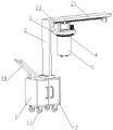
FIG. 1 is a first perspective view of the present invention;
FIG. 2 is a partial perspective view of the first embodiment of the present invention;
FIG. 3 is a partial perspective view of the second embodiment of the present invention;
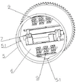
FIG. 4 is a partial cross-sectional view of the first embodiment of the present invention;
FIG. 5 is a partial sectional view of the second embodiment of the present invention;
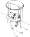
FIG. 6 is a third schematic view of a partial perspective structure of the present invention;
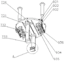
FIG. 7 is a fourth schematic view of a partial perspective structure of the present invention;
FIG. 8 is an enlarged view taken at A in FIG. 7;
fig. 9 is a schematic partial perspective view of the present invention.
Reference numerals are as follows: the device comprises a movable box 1, a universal wheel 11, a sliding door 12, a balancing weight 13, a hand push rod 14, a mounting rack 2, a screw rod sliding table 21, a connecting rack 22, a bearing disc 3, a rotating ring 4, a rotating cylinder 5, a sliding groove 51, a lifting plate 6, a rectangular groove 61, a clamping component 7, a sliding rail 71, a driving component 72, a fixing rack 721, a driving motor 722, a driving shaft 723, a driving gear 724, a driving wheel 725, a driven wheel 726, a belt 727, a clamping component 73, a sliding table 731, an L-shaped plate 732, a U-shaped plate 733, a connecting plate 734, a clamping rack 735, an elastic contact piece 736, a rubber contact piece 737, a connecting spring 738, a circular rack 8, a rotating motor 81, a rotating gear 82, a hydraulic push rod 83, a cooling component 9, a water tank 91, a rotating component 92, a first chain 921, an adjusting motor 922, a second chain wheel 923, a third chain wheel 924, a second chain 925, a water spraying component 93, a mounting seat 931, a rotating shaft 932, a rotating block 933, a vertical pipe 934, a spray nozzle 935, a first chain wheel 936 and a hose 937.
Detailed Description
In order to make the objects, technical solutions and advantages of the embodiments of the present application clearer, the technical solutions in the embodiments of the present application will be clearly and completely described below with reference to the drawings in the embodiments of the present application, and it is obvious that the described embodiments are some embodiments of the present application, but not all embodiments. The components of the embodiments of the present application, generally described and illustrated in the figures herein, can be arranged and designed in a wide variety of different configurations.
Thus, the following detailed description of the embodiments of the present application, presented in the accompanying drawings, is not intended to limit the scope of the claimed application, but is merely representative of selected embodiments of the application. All other embodiments, which can be derived by a person skilled in the art from the embodiments given herein without making any creative effort, shall fall within the protection scope of the present application.
It should be noted that the embodiments and features of the embodiments in the present application may be combined with each other without conflict.
It should be noted that: like reference numbers and letters refer to like items in the following figures, and thus, once an item is defined in one figure, it need not be further defined and explained in subsequent figures.
In the description of the embodiments of the present application, it should be noted that the indication of orientation or positional relationship is based on the orientation or positional relationship shown in the drawings, or the orientation or positional relationship which is usually placed when the product of the application is used, or the orientation or positional relationship which is usually understood by those skilled in the art, or the orientation or positional relationship which is usually placed when the product of the application is used, and is only for the convenience of describing the application and simplifying the description, but does not indicate or imply that the indicated device or element must have a specific orientation, be constructed in a specific orientation, and be operated, and thus, should not be construed as limiting the application. Furthermore, the terms "first," "second," "third," and the like are used solely to distinguish one from another and are not to be construed as indicating or implying relative importance.
In the description of the embodiments of the present application, it should also be noted that, unless otherwise explicitly stated or limited, the terms "disposed," "mounted," and "connected" are to be construed broadly, and may for example be fixedly connected, detachably connected, or integrally connected; may be directly connected or may be indirectly connected through an intermediate. The specific meaning of the above terms in the present application can be understood in a specific case by those of ordinary skill in the art.
As shown in fig. 1-9, the present invention provides a manipulator device capable of automatically closing a valve of a fire gas tank and cooling, comprising a moving box 1, a mounting frame 2, a lead screw sliding table 21, a connecting frame 22, a bearing disc 3, a rotating ring 4, a rotating cylinder 5, a lifting plate 6, a clamping assembly 7, an annular rack 8, a rotating motor 81, a rotating gear 82, two hydraulic push rods 83 and two cooling assemblies 9, wherein the bottom of the moving box 1 is provided with four universal wheels 11 distributed in a rectangular manner, the mounting frame 2 is arranged on the top of the moving box 1, the lead screw sliding table 21 is horizontally arranged on the top of the mounting frame 2, the top of the connecting frame 22 is fixedly connected with the moving end of the lead screw sliding table 21, the bearing disc 3 is fixedly connected with the bottom of the connecting frame 22, the bottom of the bearing disc 3 is provided with a sliding groove, the rotating ring 4 is slidably mounted on the sliding groove, the rotating cylinder 5 is fixedly connected with the bottom of the rotating ring 4, the inner wall of a rotating cylinder 5 is equipped with four spouts 51, lifter plate 6 slidable mounting is on four spouts 51, two hydraulic push rods 83 are the symmetry and set up the inside top at a rotating cylinder 5, and the output of two hydraulic push rods 83 and the top fixed connection of lifter plate 6, centre gripping subassembly 7 is installed on lifter plate 6, 8 covers of annular rack are established on the top outer wall of a rotating cylinder 5, the vertical setting of rotation motor 81 is at the top of bearing dish 3, and the output shaft that rotates motor 81 extends to the bottom below of bearing dish 3, rotating gear 82 and the output shaft fixed connection who rotates motor 81, and rotating gear 82 and the meshing of annular rack 8, two cooling subassembly 9 are the symmetry and set up on lifter plate 6.
The specific working process is as follows: the movable box 1 is moved to the position near a fired gas tank manually, then the lead screw sliding table 731 is operated to drive the connecting frame 22 to move, the connecting frame 22 drives the rotary cylinder 5 to move to the position right above the fired gas tank, then the two hydraulic push rods 83 are operated to drive the lifting plate 6 to move downwards in the four sliding grooves 51, the lifting plate 6 drives the clamping component 7 and the two cooling components 9 to move downwards to proper positions, then the clamping component 7 is operated to clamp a valve of the fired gas tank, then the rotary motor 81 is operated to drive the rotary gear 82 to rotate, the rotary gear 82 drives the annular rack 8 to move, the annular rack 8 drives the rotary cylinder 5 to rotate, the rotary cylinder 5 drives the rotary ring 4 to rotate in the sliding grooves, the clamping component 7 drives the valve of the gas tank to rotate while the rotary cylinder 5 rotates, and the valve rotates to be in a closed state, accomplish the operation of self-closing gas tank valve, 9 works of two last cooling module carry out the water spray cooling to the gas tank, spout the water on the gas tank and can put out probably still the fire of burning, can cool down to the jar body of gas tank simultaneously, make things convenient for follow-up manual work in time to shift to safe place with the gas tank, through above-mentioned step, the realization is carried out automatic shutdown and is carried out the water spray cooling to the gas tank that fires to the gas tank valve that fires, need not artifical manual shut-off valve, and then avoided the manual condition that causes burn and scald to take place.
In one embodiment, the clamping assembly 7 includes a sliding rail 71, a driving member 72 and two clamping members 73, the sliding rail 71 is horizontally disposed at the bottom of the lifting plate 6, the two clamping members 73 are symmetrically disposed on the sliding rail 71, each clamping member 73 includes a sliding table 731, an L-shaped plate 732, a U-shaped plate 733, a connecting plate 734, a clamping rack 735 and two elastic contact pieces 736, the sliding table 731 is slidably mounted on the sliding rail 71, the L-shaped plate 732 is mounted at the bottom of the sliding table 731, the U-shaped plate 733 is fixedly connected to the bottom end of the L-shaped plate 732, the bottom end of the connecting plate 734 is fixedly connected to the side wall of the sliding table 731, the top end of the connecting plate 734 extends to the top of the lifting plate 6, the lifting plate 6 is provided with a rectangular groove 61 for the connecting plate 734 to pass through, the clamping rack 735 is fixedly connected with the side wall of the top end of the connecting plate 734, the two elastic contact pieces 736 are symmetrically arranged in the U-shaped plate 733, and the driving part 72 is installed at the top of the lifting plate 6.
The driving part 72 drives the clamping racks 735 in the two clamping parts 73 to move relatively, the clamping racks 735 drive the connecting plate 734 to move, the connecting plate 734 drives the sliding table 731 to move on the sliding rail 71, the sliding table 731 drives the L-shaped plate 732 and the U-shaped plate 733 to move, the U-shaped plate 733 drives the two elastic contact pieces 736 to move, the elastic contact pieces 736 in the two clamping parts 73 move relatively to clamp the gas tank valve which is on fire, and the subsequent rotary motor 81 is convenient to work and drive the gas tank valve which is on fire to rotate to a closed state.
In one embodiment, each of the elastic contact pieces 736 includes a rubber contact block 737 and three connecting springs 738, one end of each of the three connecting springs 738 is fixedly connected to the U-shaped plate 733, and the rubber contact block 737 is fixedly connected to the other end of each of the three connecting springs 738.
When two elasticity support the touch multitouch 737 in the ware 736 and remove to gas tank valve department, connecting spring 738 atress compression deformation, the upper and lower both ends of gas tank valve are supported touch multitouch 737 by rubber respectively and are contradicted tightly, and the outer wall of gas tank valve is also contradicted in U template 733's inner wall department simultaneously, has reached and has pressed from both sides tight spacing purpose to the gas tank valve, and convenient follow-up drive gas tank valve rotates.
In one embodiment, the driving component 72 includes a fixing frame 721, a driving motor 722, a driving shaft 723, a driving gear 724, a driving wheel 725, a driven wheel 726 and a belt 727, the fixing frame 721 is disposed on the top of the lifting plate 6, the driving motor 722 is vertically disposed on the top of the fixing frame 721, the driving shaft 723 is rotatably mounted on the top end of the fixing frame 721, the driving gear 724 is fixedly connected with the driving shaft 723, the driving gear 724 is meshed with the clamping racks 735 of the two clamping components 73, the driving wheel 725 is fixedly connected with the output shaft of the driving motor 722, the driven wheel 726 is fixedly connected with the top end of the driving shaft 723, and the belt 727 is sleeved outside the driving wheel 725 and the driven wheel 726.
The driving wheel 725 is driven to rotate through the work of the driving motor 722, the driving wheel 725 drives the driven wheel 726 to rotate through the belt 727, the driven wheel 726 drives the driving shaft 723 to rotate, the driving shaft 723 drives the driving gear 724 to rotate, the driving gear 724 drives the clamping racks 735 in the two clamping parts 73 to move relatively, and therefore the elastic contact pieces 736 in the two clamping parts 73 can conveniently clamp and limit the valves of the fired gas tanks.
In one embodiment, each temperature reducing assembly 9 comprises a water tank 91, a rotating member 92 and a plurality of water spraying members 93, the water tank 91 is arranged on the top of the lifting plate 6, the plurality of water spraying members 93 are arranged on the bottom of the lifting plate 6 at equal intervals, and the plurality of water spraying members 93 are communicated with the water tank 91, the rotating member 92 is arranged on the top of the lifting plate 6, each water spraying member 93 comprises a mounting seat 931, a rotating shaft 932, a rotating block 933, a stand pipe 934, a spray nozzle 935, a first chain wheel 936 and a hose 937, the mounting seat 931 is arranged on the bottom of the lifting plate 6, the rotating shaft 932 is rotatably mounted in the mounting seat 931, one end of the rotating shaft 932 extends to the outside of the mounting seat 931, the rotating block 933 is arranged on the rotating shaft 932, the stand pipe 934 is mounted on the bottom of the rotating block 933, the spray nozzle 935 is mounted on the bottom of the stand pipe 934, the first chain wheel 936 and one end of the rotating shaft 932 are fixedly connected to the mounting seat 931, hose 937 has two ends respectively communicating with standpipe 934 and water tank 91.
Water in the water tank 91 enters into to the standpipe 934 through hose 937 in, then water in the standpipe 934 through shower nozzle 935 blowout, shower nozzle 935 spouts water to the gas tank on, water can put out probably still fire in the burning, can cool down to the jar body of gas tank simultaneously, in shower nozzle 935 water spray, 92 work of rotatable part drives all first sprockets 936 reciprocal rotations in the certain extent, first sprocket 936 drives shower nozzle 935 reciprocal rotations in the certain extent, and then realize the reciprocal certain within range swing of shower nozzle 935, increase shower nozzle 935's water spray scope, make things convenient for shower nozzle 935 to spout all departments on the gas tank with water.
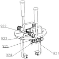
In one embodiment, the rotating member 92 includes a first chain 921, an adjusting motor 922, a second chain wheel 923, a third chain wheel 924, and a second chain 925, the first chain 921 covers all the first chain wheels 936, the adjusting motor 922 is horizontally disposed on the top of the lifting plate 6, the second chain wheel 923 is fixedly connected to the output shaft of the adjusting motor 922, the third chain wheel 924 is fixedly connected to the rotating shaft 932 in one of the water spraying members 93, and the second chain 925 covers the second chain wheel 923 and the third chain wheel 924.
Drive second sprocket 923 through the work of adjusting motor 922 and rotate, second sprocket 923 utilizes second chain 925 to drive third sprocket 924 and rotates, and third sprocket 924 drives the axis of rotation 932 rotation in one of them water spray component 93, and this axis of rotation 932 drives first chain 921 and rotates, and first chain 921 drives all first sprockets 936 and rotates, and then all first sprockets 936 drive all shower nozzles 935 and rotate, realizes shower nozzle 935 at the reciprocal rotation of within range.
In one embodiment, the movable box 1 is provided with two sliding doors 12 hinged thereto, and the interior of the movable box 1 is provided with a plurality of balancing weights 13.
The weight of balancing weight 13 increase removal case 1 has improved the stability of removal case 1, and sliding door 12 conveniently adjusts balancing weight 13's quantity according to actual conditions.
In one embodiment, the top of the mobile bin 1 is provided with a hand push bar 14.
The hand push rod 14 facilitates manual pushing of the movable box 1 to move easily.
The above description is only a preferred embodiment of the present application and is not intended to limit the present application, and various modifications and changes may be made to the present application by those skilled in the art. Any modification, equivalent replacement, improvement and the like made within the spirit and principle of the present application shall be included in the protection scope of the present application.
Claims (10)
1. The utility model provides a but mechanical hand device of self-closing gas tank valve and cooling that catches fire which characterized in that includes:
bear dish, rotating ring, rotor, lifter plate, rotation motor, rolling gear, annular rack, centre gripping subassembly, hydraulic push rod and cooling subassembly, rotor slidable mounting is on bearing the dish, rotor and rotating ring fixed connection, lifter plate slidable mounting is on the rotor, hydraulic push rod sets up the inside at the rotor to hydraulic push rod's output with the top of lifter plate is connected, the centre gripping unit mount is in on the lifter plate, annular rack cover is established on the top of rotor, the rotation motor sets up the top at bearing the dish, on the output shaft of motor was rotated in the installation of rotating gear, and with annular rack meshing, cooling subassembly sets up on the lifter plate.
2. The robot apparatus capable of automatically closing a valve of a fire gas tank and cooling down according to claim 1, further comprising:
the movable box comprises a movable box body, a mounting frame, a lead screw sliding table and a connecting frame, wherein the mounting frame is arranged at the top of the movable box body, the lead screw sliding table is arranged at the top end of the mounting frame, the top end of the connecting frame is fixedly connected with the movable end of the lead screw sliding table, and the bearing disc is fixedly connected with the bottom end of the connecting frame.
3. The mechanical arm device capable of automatically closing the valve of the fire-catching gas tank and cooling the fire-catching gas tank as claimed in claim 2, wherein the moving box is provided with two sliding doors hinged with the moving box, and a plurality of balancing weights are arranged inside the moving box.
4. The manipulator device capable of automatically closing the valve of the fire coal gas tank and cooling down as claimed in claim 2 or 3, wherein a hand push rod is provided on the top of the moving box.
5. The mechanical arm device capable of automatically closing the valve of the fire coal gas tank and cooling the fire coal gas tank according to claim 1, wherein the clamping assembly comprises a sliding rail, a driving part and two clamping parts, the sliding rail is horizontally arranged at the bottom of the lifting plate, the two clamping parts are symmetrically arranged on the sliding rail, and each clamping part comprises a sliding table, an L-shaped plate, a U-shaped plate, a connecting plate, a clamping rack and two elastic abutting parts.
6. The mechanical arm device capable of automatically closing the valve of the fire-catching gas tank and cooling the valve of the fire-catching gas tank as claimed in claim 5, wherein the sliding table is slidably mounted on a sliding rail, the L-shaped plate is mounted at the bottom of the sliding table, the U-shaped plate is fixedly connected with the bottom end of the L-shaped plate, the bottom end of the connecting plate is fixedly connected with the side wall of the sliding table, the top end of the connecting plate extends to the upper part of the top of the lifting plate, a rectangular groove for the connecting plate to pass through is formed in the lifting plate, and the clamping rack is fixedly connected with the side wall of the top end of the connecting plate.
7. The mechanical arm device capable of automatically closing the valve of the fire coal gas tank and cooling as claimed in claim 5, wherein two elastic abutting pieces are symmetrically arranged in a U-shaped plate, each elastic abutting piece comprises a rubber abutting block and three connecting springs, one end of each connecting spring is fixedly connected with the U-shaped plate, and the rubber abutting block is fixedly connected with the other end of each connecting spring.
8. The mechanical arm device capable of automatically closing the valve of the fire gas tank and cooling as claimed in claim 5, wherein the driving component is mounted at the top of the lifting plate, the driving component comprises a fixing frame, a driving motor, a driving shaft, a driving gear, a driving wheel, a driven wheel and a belt, the fixing frame is arranged at the top of the lifting plate, the driving motor is vertically arranged at the top of the fixing frame, the driving shaft is rotatably mounted at the top end of the fixing frame, the driving gear is fixedly connected with the driving shaft, the driving gear is meshed with clamping racks in the two clamping components, the driving wheel is fixedly connected with an output shaft of the driving motor, the driven wheel is fixedly connected with the top end of the driving shaft, and the belt is sleeved outside the driving wheel and the driven wheel.
9. The manipulator device for automatically closing the valve of the fire-catching gas tank and cooling the fire-catching gas tank according to claim 1, wherein each cooling assembly comprises a water tank, a rotating member and a plurality of water spraying members, the water tank is disposed on the top of the lifting plate, the plurality of water spraying members are disposed on the bottom of the lifting plate at equal intervals, the plurality of water spraying members are communicated with the water tank, the rotating member is disposed on the top of the lifting plate, each water spraying member comprises a mounting seat, a rotating shaft, a rotating block, a vertical pipe, a nozzle, a first chain wheel and a hose, the mounting seat is disposed on the bottom of the lifting plate, the rotating shaft is rotatably mounted in the mounting seat, one end of the rotating shaft extends to the outside of the mounting seat, the rotating block is disposed on the rotating shaft, the vertical pipe is mounted on the bottom of the rotating block, and the nozzle is mounted on the bottom of the vertical pipe, the first chain wheel is fixedly connected with one end, extending to the outside of the mounting seat, of the rotating shaft, and the two ends of the hose are respectively communicated with the vertical pipe and the water tank.
10. The manipulator device of claim 9, wherein the rotating member comprises a first chain, an adjusting motor, a second chain, a third chain and a second chain, the first chain is sleeved on the outside of all the first chains, the adjusting motor is horizontally disposed on the top of the lifting plate, the second chain is fixedly connected to the output shaft of the adjusting motor, the third chain is fixedly connected to the rotating shaft of one of the water spraying members, and the second chain is sleeved on the outside of the second chain and the third chain.
Priority Applications (1)
| Application Number | Priority Date | Filing Date | Title |
|---|---|---|---|
| CN202210677004.8A CN114750186B (en) | 2022-06-16 | 2022-06-16 | Mechanical arm device capable of automatically closing valve of fire-catching gas tank and cooling |
Applications Claiming Priority (1)
| Application Number | Priority Date | Filing Date | Title |
|---|---|---|---|
| CN202210677004.8A CN114750186B (en) | 2022-06-16 | 2022-06-16 | Mechanical arm device capable of automatically closing valve of fire-catching gas tank and cooling |
Publications (2)
| Publication Number | Publication Date |
|---|---|
| CN114750186A true CN114750186A (en) | 2022-07-15 |
| CN114750186B CN114750186B (en) | 2022-10-21 |
Family
ID=82337125
Family Applications (1)
| Application Number | Title | Priority Date | Filing Date |
|---|---|---|---|
| CN202210677004.8A Active CN114750186B (en) | 2022-06-16 | 2022-06-16 | Mechanical arm device capable of automatically closing valve of fire-catching gas tank and cooling |
Country Status (1)
| Country | Link |
|---|---|
| CN (1) | CN114750186B (en) |
Cited By (2)
| Publication number | Priority date | Publication date | Assignee | Title |
|---|---|---|---|---|
| CN118238275A (en) * | 2024-05-21 | 2024-06-25 | 华侨大学 | Ceramic clay kneading robot |
| CN118424613A (en) * | 2024-05-29 | 2024-08-02 | 安徽省锐凌计量器制造有限公司 | A device and method for monitoring gas leakage using liquid level detection principle |
Citations (14)
| Publication number | Priority date | Publication date | Assignee | Title |
|---|---|---|---|---|
| CN108776014A (en) * | 2018-09-08 | 2018-11-09 | 江苏容大材料腐蚀检验有限公司 | Valve detection machine |
| CN108931361A (en) * | 2018-05-22 | 2018-12-04 | 山东和富工程检测有限公司 | A kind of automatic sprinkler system valve working cycle performance automatic test equipment |
| CN208468367U (en) * | 2018-05-04 | 2019-02-05 | 深圳市恒通智能自动化科技有限公司 | It is a kind of can height adjustment machinery automation processing clamping device |
| CN209111110U (en) * | 2018-10-16 | 2019-07-16 | 郑州煤机综机设备有限公司 | A kind of automatic up and down device of achievable piston rod |
| CN110653833A (en) * | 2019-10-23 | 2020-01-07 | 唐山旺发压铸有限公司 | Casting machine cooling manipulator with movement track memory function |
| CN111633670A (en) * | 2020-04-22 | 2020-09-08 | 长春职业技术学院 | Sorting manipulator for linear output of formed mechanical parts |
| CN111872969A (en) * | 2020-08-05 | 2020-11-03 | 温州市渡绪春电子科技有限公司 | Mechanical arm device capable of automatically closing valve of fire-catching gas tank and cooling |
| CN112247805A (en) * | 2020-10-18 | 2021-01-22 | 安徽恩大阀门机械有限公司 | A polishing device for valve processing and manufacturing |
| DE212020000579U1 (en) * | 2020-10-15 | 2021-12-14 | Suzhou Saiya Intelligent Technology Co. Ltd. | An automated mechanism for handling claw material |
| CN113814222A (en) * | 2021-11-03 | 2021-12-21 | 重庆芯洁科技有限公司 | PVD part high pressure washing equipment |
| CN215641323U (en) * | 2021-09-08 | 2022-01-25 | 哈尔滨海关技术中心 | Automatic clamping device for detection reagent |
| WO2022045057A1 (en) * | 2020-08-28 | 2022-03-03 | 日本製鉄株式会社 | Press molded article manufacturing method, conveyance device for heated workpiece, and hot press manufacturing line |
| CN216030794U (en) * | 2021-08-17 | 2022-03-15 | 龙江周 | An industrial robot loading and unloading claw |
| CN114406782A (en) * | 2022-03-09 | 2022-04-29 | 郑州工业应用技术学院 | A hydraulic mechanical claw for feeding |
-
2022
- 2022-06-16 CN CN202210677004.8A patent/CN114750186B/en active Active
Patent Citations (14)
| Publication number | Priority date | Publication date | Assignee | Title |
|---|---|---|---|---|
| CN208468367U (en) * | 2018-05-04 | 2019-02-05 | 深圳市恒通智能自动化科技有限公司 | It is a kind of can height adjustment machinery automation processing clamping device |
| CN108931361A (en) * | 2018-05-22 | 2018-12-04 | 山东和富工程检测有限公司 | A kind of automatic sprinkler system valve working cycle performance automatic test equipment |
| CN108776014A (en) * | 2018-09-08 | 2018-11-09 | 江苏容大材料腐蚀检验有限公司 | Valve detection machine |
| CN209111110U (en) * | 2018-10-16 | 2019-07-16 | 郑州煤机综机设备有限公司 | A kind of automatic up and down device of achievable piston rod |
| CN110653833A (en) * | 2019-10-23 | 2020-01-07 | 唐山旺发压铸有限公司 | Casting machine cooling manipulator with movement track memory function |
| CN111633670A (en) * | 2020-04-22 | 2020-09-08 | 长春职业技术学院 | Sorting manipulator for linear output of formed mechanical parts |
| CN111872969A (en) * | 2020-08-05 | 2020-11-03 | 温州市渡绪春电子科技有限公司 | Mechanical arm device capable of automatically closing valve of fire-catching gas tank and cooling |
| WO2022045057A1 (en) * | 2020-08-28 | 2022-03-03 | 日本製鉄株式会社 | Press molded article manufacturing method, conveyance device for heated workpiece, and hot press manufacturing line |
| DE212020000579U1 (en) * | 2020-10-15 | 2021-12-14 | Suzhou Saiya Intelligent Technology Co. Ltd. | An automated mechanism for handling claw material |
| CN112247805A (en) * | 2020-10-18 | 2021-01-22 | 安徽恩大阀门机械有限公司 | A polishing device for valve processing and manufacturing |
| CN216030794U (en) * | 2021-08-17 | 2022-03-15 | 龙江周 | An industrial robot loading and unloading claw |
| CN215641323U (en) * | 2021-09-08 | 2022-01-25 | 哈尔滨海关技术中心 | Automatic clamping device for detection reagent |
| CN113814222A (en) * | 2021-11-03 | 2021-12-21 | 重庆芯洁科技有限公司 | PVD part high pressure washing equipment |
| CN114406782A (en) * | 2022-03-09 | 2022-04-29 | 郑州工业应用技术学院 | A hydraulic mechanical claw for feeding |
Cited By (2)
| Publication number | Priority date | Publication date | Assignee | Title |
|---|---|---|---|---|
| CN118238275A (en) * | 2024-05-21 | 2024-06-25 | 华侨大学 | Ceramic clay kneading robot |
| CN118424613A (en) * | 2024-05-29 | 2024-08-02 | 安徽省锐凌计量器制造有限公司 | A device and method for monitoring gas leakage using liquid level detection principle |
Also Published As
| Publication number | Publication date |
|---|---|
| CN114750186B (en) | 2022-10-21 |
Similar Documents
| Publication | Publication Date | Title |
|---|---|---|
| CN114750186B (en) | Mechanical arm device capable of automatically closing valve of fire-catching gas tank and cooling | |
| CN210114948U (en) | Industrial waste gas high-efficiency treatment device | |
| CN110173727A (en) | The device that the oil smoke of a kind of pair of domestic type smoke exhaust ventilator absorption is cleaned | |
| CN117900066B (en) | Valve spraying process and equipment | |
| CN112387721A (en) | Thermal power plant exhaust chimney cleaning device | |
| CN110701545A (en) | Emergency box lamp | |
| CN211432439U (en) | Automatic baking oven for food processing | |
| CN112221775B (en) | Robot spraying device with tail gas treatment function | |
| CN107899825B (en) | A kind of elevator manufacture plate paint spraying apparatus | |
| CN216323603U (en) | Cleaning type pretreatment device for processing pipeline flange | |
| CN207505828U (en) | A kind of rotary-type full-automatic food frying machine | |
| CN216965681U (en) | Reaction kettle cleaning machine | |
| CN216277043U (en) | Safe anti-falling device for building construction | |
| CN212445249U (en) | Marine petroleum pipeline maintenance robot | |
| CN221076950U (en) | Novel spray cooling device | |
| CN220658036U (en) | Environment-friendly paint spraying device for furniture | |
| CN210847476U (en) | Raise dust monitor cleaning device | |
| CN113585674A (en) | Wall spraying device for decoration | |
| CN109226115B (en) | Vertical deep hole saturated steam cleaning machine | |
| CN223530621U (en) | A metal parts painting device | |
| CN114408362A (en) | Production of toughened glass is with taking washing abrasionproof strorage device | |
| CN221222121U (en) | Electrical explosion-proof monitoring equipment convenient to dismouting maintenance | |
| CN217043318U (en) | Spraying baking finish device for liquefied petroleum gas tank | |
| CN216703798U (en) | A workshop dust fall mechanism for leather processing | |
| CN218115503U (en) | Vertical lifting mechanism for super-long and super-deep cold water tank |
Legal Events
| Date | Code | Title | Description |
|---|---|---|---|
| PB01 | Publication | ||
| PB01 | Publication | ||
| SE01 | Entry into force of request for substantive examination | ||
| SE01 | Entry into force of request for substantive examination | ||
| GR01 | Patent grant | ||
| GR01 | Patent grant |