CN114709050A - Improved current transformer mounting structure - Google Patents
Improved current transformer mounting structure Download PDFInfo
- Publication number
- CN114709050A CN114709050A CN202210464556.0A CN202210464556A CN114709050A CN 114709050 A CN114709050 A CN 114709050A CN 202210464556 A CN202210464556 A CN 202210464556A CN 114709050 A CN114709050 A CN 114709050A
- Authority
- CN
- China
- Prior art keywords
- current transformer
- mounting
- clamping block
- mounting structure
- gasket
- Prior art date
- Legal status (The legal status is an assumption and is not a legal conclusion. Google has not performed a legal analysis and makes no representation as to the accuracy of the status listed.)
- Pending
Links
Images


Classifications
-
- H—ELECTRICITY
- H01—ELECTRIC ELEMENTS
- H01F—MAGNETS; INDUCTANCES; TRANSFORMERS; SELECTION OF MATERIALS FOR THEIR MAGNETIC PROPERTIES
- H01F27/00—Details of transformers or inductances, in general
- H01F27/06—Mounting, supporting, or suspending transformers, reactors, or choke coils not being of the signal type
-
- H—ELECTRICITY
- H01—ELECTRIC ELEMENTS
- H01F—MAGNETS; INDUCTANCES; TRANSFORMERS; SELECTION OF MATERIALS FOR THEIR MAGNETIC PROPERTIES
- H01F27/00—Details of transformers or inductances, in general
- H01F27/08—Cooling; Ventilating
-
- Y—GENERAL TAGGING OF NEW TECHNOLOGICAL DEVELOPMENTS; GENERAL TAGGING OF CROSS-SECTIONAL TECHNOLOGIES SPANNING OVER SEVERAL SECTIONS OF THE IPC; TECHNICAL SUBJECTS COVERED BY FORMER USPC CROSS-REFERENCE ART COLLECTIONS [XRACs] AND DIGESTS
- Y02—TECHNOLOGIES OR APPLICATIONS FOR MITIGATION OR ADAPTATION AGAINST CLIMATE CHANGE
- Y02E—REDUCTION OF GREENHOUSE GAS [GHG] EMISSIONS, RELATED TO ENERGY GENERATION, TRANSMISSION OR DISTRIBUTION
- Y02E10/00—Energy generation through renewable energy sources
- Y02E10/50—Photovoltaic [PV] energy
Landscapes
- Engineering & Computer Science (AREA)
- Power Engineering (AREA)
- Transformers For Measuring Instruments (AREA)
Abstract
The invention relates to the technical field of current transformer equipment, in particular to an improved mounting structure of a current transformer, which comprises a mounting seat and mounting holes formed in two sides of the mounting seat, wherein a supporting rod is arranged on the upper side of the mounting seat, an adjusting seat is arranged on the supporting rod, a mounting plate is arranged on one side of the adjusting seat, an insulating plate is arranged on the upper side of the mounting plate, the current transformer is arranged on the upper side of the insulating plate, a limiting block is arranged on the lower side of the supporting rod, a locking nut is arranged at the bottom of the supporting rod, the adjusting seat comprises a first clamping block, a second clamping block and a gasket, a screw rod penetrating through the second clamping block is arranged on one side of the first clamping block, and an adjusting nut is arranged at one end of the screw rod. The mounting seat is adopted to mount the supporting rod, so that the current transformer can be conveniently suspended to be arranged, the mounting layout space is increased, the heat dissipation effect is ensured, in addition, the current transformer can be arranged at different positions on the upper side and the lower side of the mounting plate, the mounting flexibility is improved, and the control and adjustment of mounting personnel according to the actual environment are facilitated.
Description
Technical Field
The invention relates to the technical field of current transformer equipment, in particular to an improved installation structure of a current transformer.
Background
The current transformer principle is based on the electromagnetic induction principle, and the current transformer consists of a closed iron core and a winding. The primary winding of the current transformer is few in turns and is connected in series in a circuit of current to be measured, so that all current of the circuit usually flows through the current transformer, the secondary winding is more in turns and is connected in series in a measuring instrument and a protection loop, and the secondary loop of the current transformer is closed all the time when the current transformer works, so that the impedance of a series coil of the measuring instrument and the protection loop is very small, the working state of the current transformer is close to a short circuit, and a special mounting structure is required to be used for fixing the current transformer when the current transformer is mounted.
When measuring large current of alternating current, the current needs to be converted into more uniform current (China stipulates that the secondary rating of a current transformer is 5A or 1A) for facilitating secondary instrument measurement, and the voltage on a line is higher, so that direct measurement is very dangerous. The current transformer is a sensor for acquiring current information of an electrical primary loop by secondary equipment such as a measuring instrument and relay protection in a power system, converts high current into low current in proportion, is connected with the primary system on the primary side and is connected with the measuring instrument and the relay protection on the secondary side.
When the transformer works normally, the secondary side of the transformer is in an approximate short circuit state, and the output voltage is very low. In operation, if the secondary winding is open or abnormal current (such as lightning current, resonant overcurrent, capacitor charging current, inductor starting current, etc.) flows through the primary winding, overvoltage of thousands of volts or even tens of thousands of volts is generated on the secondary side. The insulation of a secondary system is damaged, the mutual inductor is burnt due to overexcitation, and even the life safety of operating personnel is endangered.
The current transformer plays a role in current transformation and electrical isolation, and is generally mounted on a metal framework or directly fixed on a wall surface by using foundation bolts when a bus passes through a wall or a floor according to the mounting requirement of the current transformer according to the situation.
Current current transformer mounting structure is being relatively poor in the fixed of current protector, leads to current transformer easily to drop, and current mounting structure with place the face and be connected comparatively simply, easily drop, and be not convenient for adjust. The use method is single, can not adapt to various installation environment, and when the mutual-inductor shell was installed on the wall or the metal plate frame, can't be according to the installation environment, the heat dissipation space of adjusting the mutual-inductor shell for the heat that the mutual-inductor shell produced is difficult to the effluvium.
Disclosure of Invention
The invention aims to solve the defects in the prior art and provides an improved mounting structure of a current transformer.
In order to achieve the purpose, the invention adopts the following technical scheme:
the utility model provides a modified current transformer's mounting structure, includes the mount pad and sets up the mounting hole in the mount pad both sides, the mount pad upside is equipped with the bracing piece, be equipped with on the bracing piece and adjust the seat, it is equipped with the mounting panel to adjust seat one side, the mounting panel upside is equipped with the insulation board, the insulation board upside is equipped with current transformer, the bracing piece downside is equipped with the stopper, the bracing piece bottom is equipped with lock nut, it includes first clamp splice, second clamp splice and gasket to adjust the seat, first clamp splice one side is equipped with the screw rod that runs through the second clamp splice, screw rod one end is equipped with adjusting nut, the gasket is equipped with two sets ofly, and it is inboard to divide to establish first clamp splice and second clamp splice, the gasket inboard is equipped with spacing, the slide opening has been seted up at the gasket middle part.
Preferably, the mounting seat is inverted U-shaped, and the mounting holes are provided with a plurality of groups which are respectively arranged at two sides of the mounting seat.
Preferably, the support rod is provided with a plurality of clamping rings matched with the limiting strips, and the clamping rings are uniformly arranged on the support rod.
Preferably, the support rod penetrates through the mounting seat, and the locking nut abuts against the inner side of the bottom of the mounting seat.
Preferably, the first clamping block and the second clamping block are respectively arranged on two sides of the supporting rod, and the gasket is abutted against the supporting rod.
Preferably, the first clamping block is connected with the second clamping block through an adjusting nut and a screw rod.
Preferably, the sliding hole and the screw rod are arranged correspondingly and are in sliding connection.
Preferably, the mounting plate is detachably connected with the insulating plate, and the current transformer is connected with the insulating plate through screws.
The invention has the beneficial effects that:
compared with the prior art, the mounting seat mounting support rod is adopted, the current transformers are conveniently arranged in a suspended mode, the mounting layout space is increased, the heat dissipation effect is ensured, the current transformers can be arranged at different positions on the upper side and the lower side of the mounting plate, the mounting flexibility is improved, and control and adjustment of mounting personnel according to actual environments are facilitated.
Drawings
Fig. 1 is a schematic three-dimensional structure diagram of a mounting structure of an improved current transformer according to the present invention;
fig. 2 is a front sectional structural schematic view of an improved mounting structure of a current transformer according to the present invention;
fig. 3 is a schematic three-dimensional structural diagram of an adjusting seat and a mounting plate of an improved mounting structure of a current transformer according to the present invention;
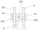
fig. 4 is a schematic structural diagram of an adjusting seat of an improved current transformer mounting structure according to the present invention.
In the figure: the current transformer comprises a mounting plate 1, an insulating plate 11, a current transformer 2, a supporting rod 3, a limiting block 31, a clamping ring 32, an adjusting seat 4, a first clamping block 41, a second clamping block 42, an adjusting nut 43, a screw rod 431, a gasket 44, a limiting strip 441, a sliding hole 442, a mounting seat 5, a mounting hole 6 and a locking nut 7.
Detailed Description
The technical solutions in the embodiments of the present invention will be clearly and completely described below with reference to the drawings in the embodiments of the present invention, and it is obvious that the described embodiments are only a part of the embodiments of the present invention, and not all of the embodiments. The following description of at least one exemplary embodiment is merely illustrative in nature and is in no way intended to limit the invention, its application, or uses. All other embodiments, which can be derived by a person skilled in the art from the embodiments given herein without making any creative effort, shall fall within the protection scope of the present invention.
Referring to fig. 1-4, an improved current transformer mounting structure includes a mounting seat 5 and mounting holes 6 formed in two sides of the mounting seat 5, a support rod 3 is arranged on the upper side of the mounting seat 5, an adjusting seat 4 is arranged on the support rod 3, a mounting plate 1 is arranged on one side of the adjusting seat 4, an insulation plate 11 is arranged on the upper side of the mounting plate 1, a current transformer 2 is arranged on the upper side of the insulation plate 11, a limiting block 31 is arranged on the lower side of the support rod 3, a locking nut 7 is arranged at the bottom of the support rod 3, the adjusting seat 4 includes a first clamping block 41, a second clamping block 42 and a gasket 44, a screw rod 431 penetrating through the second clamping block 42 is arranged on one side of the first clamping block 41, an adjusting nut 43 is arranged on one end of the screw rod 431, two groups of gaskets 44 are arranged, the inner sides of the first clamping block 41 and the second clamping block 42 are respectively arranged, a limiting strip 441 is arranged on the inner side of the gasket 44, and a slide hole 442 is formed in the middle of the gasket 44.
In this embodiment, mount pad 5 is the rectangle font, and mounting hole 6 is equipped with the multiunit, establishes 5 both sides of mount pad separately, is convenient for fixed mounting 5, the different installation face of adaptation, and nimble equipment improves equipment fixing practicality and reliability.
Specifically, offer the snap ring 32 with spacing 441 adaptation on the bracing piece 3, snap ring 32 is equipped with the multiunit, evenly set up on bracing piece 3, spacing 441 and snap ring 32 adaptation, the first clamp splice 41 of chucking and second clamp splice 42, bracing piece 3 runs through mount pad 5, lock nut 7 offsets with 5 bottom inboards of mount pad, the fixed support pole 3 of being convenient for, can set up the through-hole on mount pad 5 as required for fixed support pole 3, adjust fixed position in a flexible way, be used for installing current transformer 2.
Specifically, the first clamping block 41 and the second clamping block 42 are respectively arranged on two sides of the supporting rod 3, the gasket 44 abuts against the supporting rod 3, the height of the mounting plate 1 can be adjusted conveniently, the device can be flexibly mounted, the first clamping block 41 and the second clamping block 42 are connected through the adjusting nut 43 and the screw rod 431, the sliding hole 442 and the screw rod 431 are correspondingly arranged and are in sliding connection, and the height of the adjusting seat 4 can be accurately adjusted.
Specifically, for can dismantling between mounting panel 1 and the insulation board 11 and be connected, connect through bolt, screw or draw-in groove, improve and connect the reliability, the dismantlement of being convenient for simultaneously, the operating personnel of being convenient for carries out the dismouting, improves maintenance efficiency, through the screw connection between current transformer 2 and the insulation board 11, improves the dismouting flexibility, ensures the installation stability simultaneously, avoids the circuit electric leakage through insulation board 11 simultaneously, causes the influence to current transformer 2, interferes the testing result.
In this embodiment, mount pad 5 passes through mounting hole 6 to be fixed on box or wall, improve equipment fixing reliability and installation convenience, set up the through-hole on the mount pad 5, the erection bracing pole 3 of being convenient for, adjust seat 4 height-adjusting on the bracing piece 3, press from both sides tight first clamp splice 41 and second clamp splice 42 through adjusting nut 43, offset with bracing piece 3 through gasket 44, realize fixed locking and adjust seat 4, current transformer 2 passes through the screw and is connected with insulation board 11, insulation board 11 is installed on mounting panel 1, be convenient for detect line current.
The electric wire passes through the current transformer 2, the induced current is generated through the induced current change of the coil in the current transformer 2, and the current change in the electric wire is detected through detecting the induced current change. Set up current transformer 2 through equipment is unsettled, ensure the heat dissipation space, avoid the heat to pile up, cause the influence to equipment, destroy equipment even, cause the conflagration.
In the description of the present invention, it is to be understood that the terms "center", "longitudinal", "lateral", "length", "width", "thickness", "upper", "lower", "front", "rear", "left", "right", "vertical", "horizontal", "top", "bottom", "inner", "outer", "clockwise", "counterclockwise", and the like, indicate orientations and positional relationships based on those shown in the drawings, and are used only for convenience of description and simplicity of description, and do not indicate or imply that the equipment or element being referred to must have a particular orientation, be constructed and operated in a particular orientation, and thus, should not be considered as limiting the present invention.
Furthermore, the terms "first", "second" and "first" are used for descriptive purposes only and are not to be construed as indicating or implying relative importance or to implicitly indicate the number of technical features indicated. Thus, a feature defined as "first" or "second" may explicitly or implicitly include one or more of that feature. In the description of the present invention, "a plurality" means two or more unless specifically defined otherwise.
The above description is only for the preferred embodiment of the present invention, but the scope of the present invention is not limited thereto, and any person skilled in the art should be considered as the technical solutions and the inventive concepts of the present invention within the technical scope of the present invention.
It is noted that the terminology used herein is for the purpose of describing particular embodiments only and is not intended to be limiting of example embodiments according to the present application. As used herein, the singular forms "a", "an" and "the" are intended to include the plural forms as well, and it should be understood that when the terms "comprises" and/or "comprising" are used in this specification, they specify the presence of stated features, steps, operations, devices, components, and/or combinations thereof, unless the context clearly indicates otherwise.
The relative arrangement of the components and steps, the numerical expressions and numerical values set forth in these embodiments do not limit the scope of the present invention unless specifically stated otherwise. Meanwhile, it should be understood that the sizes of the respective portions shown in the drawings are not drawn in an actual proportional relationship for the convenience of description. Techniques, methods, and apparatus known to those of ordinary skill in the relevant art may not be discussed in detail but are intended to be part of the specification where appropriate. In all examples shown and discussed herein, any particular value should be construed as merely illustrative, and not limiting. Thus, other examples of the exemplary embodiments may have different values. It should be noted that: like reference numbers and letters refer to like items in the following figures, and thus, once an item is defined in one figure, further discussion thereof is not required in subsequent figures.
Claims (8)
1. A modified current transformer's mounting structure, includes mount pad (5) and sets up mounting hole (6) in mount pad (5) both sides, its characterized in that, mount pad (5) upside is equipped with bracing piece (3), be equipped with on bracing piece (3) and adjust seat (4), it is equipped with mounting panel (1) to adjust seat (4) one side, mounting panel (1) upside is equipped with insulation board (11), insulation board (11) upside is equipped with current transformer (2), bracing piece (3) downside is equipped with stopper (31), bracing piece (3) bottom is equipped with lock nut (7), adjust seat (4) including first clamp splice (41), second clamp splice (42) and gasket (44), first clamp splice (41) one side is equipped with screw rod (431) that run through second clamp splice (42), screw rod (431) one end is equipped with adjusting nut (43), the gasket (44) is provided with two groups, which are respectively provided with a first clamping block (41) and a second clamping block (42) at the inner side, a limiting strip (441) is arranged at the inner side of the gasket (44), and a sliding hole (442) is formed in the middle of the gasket (44).
2. An improved current transformer mounting structure as claimed in claim 1, wherein said mounting base (5) is inverted U-shaped, and said mounting holes (6) are provided in plural sets, respectively on both sides of said mounting base (5).
3. The improved mounting structure of the current transformer according to claim 1, wherein the support rod (3) is provided with a plurality of clamping rings (32) matched with the limiting strips (441), and the plurality of groups of clamping rings (32) are uniformly arranged on the support rod (3).
4. An improved current transformer mounting structure as claimed in claim 3, wherein said support rod (3) penetrates through the mounting base (5), and said lock nut (7) abuts against the inner side of the bottom of the mounting base (5).
5. An improved current transformer mounting structure as claimed in claim 1, wherein said first clamping block (41) and said second clamping block (42) are respectively disposed at two sides of said supporting rod (3), and said gasket (44) is abutted against said supporting rod (3).
6. The improved current transformer mounting structure of claim 5, wherein the first clamping block (41) and the second clamping block (42) are connected through an adjusting nut (43) and a screw (431).
7. An improved mounting structure of a current transformer according to claim 6, characterized in that the sliding hole (442) is corresponding to the screw rod (431) and is connected in a sliding way.
8. An improved current transformer mounting structure according to claim 1, wherein the mounting plate (1) is detachably connected with the insulating plate (11), and the current transformer (2) is connected with the insulating plate (11) through screws.
Priority Applications (1)
| Application Number | Priority Date | Filing Date | Title |
|---|---|---|---|
| CN202210464556.0A CN114709050A (en) | 2022-04-29 | 2022-04-29 | Improved current transformer mounting structure |
Applications Claiming Priority (1)
| Application Number | Priority Date | Filing Date | Title |
|---|---|---|---|
| CN202210464556.0A CN114709050A (en) | 2022-04-29 | 2022-04-29 | Improved current transformer mounting structure |
Publications (1)
| Publication Number | Publication Date |
|---|---|
| CN114709050A true CN114709050A (en) | 2022-07-05 |
Family
ID=82177376
Family Applications (1)
| Application Number | Title | Priority Date | Filing Date |
|---|---|---|---|
| CN202210464556.0A Pending CN114709050A (en) | 2022-04-29 | 2022-04-29 | Improved current transformer mounting structure |
Country Status (1)
| Country | Link |
|---|---|
| CN (1) | CN114709050A (en) |
Citations (7)
| Publication number | Priority date | Publication date | Assignee | Title |
|---|---|---|---|---|
| KR20160049936A (en) * | 2014-10-28 | 2016-05-10 | 대우조선해양 주식회사 | Current transformers for switchboard locations adjustment fixture |
| CN207259070U (en) * | 2017-08-28 | 2018-04-20 | 荆州市江陵申达电气有限公司 | A kind of transformer installation lifting gear |
| CN211245604U (en) * | 2019-10-30 | 2020-08-14 | 天津儒礼科技有限公司 | Fixing device of soxhlet extractor |
| CN211427982U (en) * | 2020-04-08 | 2020-09-04 | 广西惠明电气有限公司 | Current transformer installation device |
| CN111627658A (en) * | 2020-05-29 | 2020-09-04 | 浙江全瑞本科技股份有限公司 | Strut type bus current transformer |
| CN215265825U (en) * | 2021-04-21 | 2021-12-21 | 上海浙琪电器有限公司 | Current transformer with mounting seat coated with insulating material |
| CN216586265U (en) * | 2021-11-11 | 2022-05-24 | 广东安达交通工程有限公司 | Liftable traffic sign tablet |
-
2022
- 2022-04-29 CN CN202210464556.0A patent/CN114709050A/en active Pending
Patent Citations (7)
| Publication number | Priority date | Publication date | Assignee | Title |
|---|---|---|---|---|
| KR20160049936A (en) * | 2014-10-28 | 2016-05-10 | 대우조선해양 주식회사 | Current transformers for switchboard locations adjustment fixture |
| CN207259070U (en) * | 2017-08-28 | 2018-04-20 | 荆州市江陵申达电气有限公司 | A kind of transformer installation lifting gear |
| CN211245604U (en) * | 2019-10-30 | 2020-08-14 | 天津儒礼科技有限公司 | Fixing device of soxhlet extractor |
| CN211427982U (en) * | 2020-04-08 | 2020-09-04 | 广西惠明电气有限公司 | Current transformer installation device |
| CN111627658A (en) * | 2020-05-29 | 2020-09-04 | 浙江全瑞本科技股份有限公司 | Strut type bus current transformer |
| CN215265825U (en) * | 2021-04-21 | 2021-12-21 | 上海浙琪电器有限公司 | Current transformer with mounting seat coated with insulating material |
| CN216586265U (en) * | 2021-11-11 | 2022-05-24 | 广东安达交通工程有限公司 | Liftable traffic sign tablet |
Similar Documents
| Publication | Publication Date | Title |
|---|---|---|
| US9413103B2 (en) | Compact connection system for mains switchgear | |
| CA2436800A1 (en) | Apparatus and method for detecting and calculating ground fault resistance | |
| KR101488104B1 (en) | System for Detecting Open Phase on a Connection Line of Stand-by Transformer in Nuclear Power Plant by Using Rogowski Coil | |
| CN205562655U (en) | A closed loop opening current sensor for measuring transformer neutral point electric current | |
| CN114743759B (en) | Transformer machine case structure convenient to installation | |
| CN203012082U (en) | Insulation detector | |
| CN212928646U (en) | Transformer damping device | |
| CN106908687A (en) | Secondary loop of mutual inductor detection means | |
| CN211427982U (en) | Current transformer installation device | |
| CN210039896U (en) | Voltage transformer capable of preventing iron core from being grounded at multiple points | |
| CN211374940U (en) | 500kV zinc oxide arrester high altitude testing arrangement | |
| CN114002618A (en) | Non-contact multifunctional sensor | |
| CN221376517U (en) | Simple measuring line tool | |
| CN208834876U (en) | A kind of novel current transformer | |
| CN201048243Y (en) | Armoured withdraw type high-tension switch cabinet | |
| CN222600721U (en) | Mutual inductor operation indicating device | |
| CN217741312U (en) | Open circuit protection device and mutual inductor system | |
| CN223039894U (en) | An isolated adjustable AC/DC power supply box | |
| CN211699921U (en) | Rogowski coil lightning current sensor mounting device of traction power supply system | |
| CN220983991U (en) | Alarm device for transformer fault | |
| CN224231743U (en) | Modularized gas collection vibration monitoring device based on oil immersed transformer | |
| CN221007835U (en) | Novel alarm structure in withstand voltage AC/DC test overcurrent hardware | |
| CN117856048B (en) | A modular power metering box | |
| CN211179972U (en) | 10kV line voltage transformer accessory | |
| CN213845893U (en) | An electric shock-proof switch cabinet |
Legal Events
| Date | Code | Title | Description |
|---|---|---|---|
| PB01 | Publication | ||
| PB01 | Publication | ||
| SE01 | Entry into force of request for substantive examination | ||
| SE01 | Entry into force of request for substantive examination | ||
| RJ01 | Rejection of invention patent application after publication | ||
| RJ01 | Rejection of invention patent application after publication |
Application publication date: 20220705 |