CN114684709A - Gantry group-hoisting operation method for track line - Google Patents
Gantry group-hoisting operation method for track line Download PDFInfo
- Publication number
- CN114684709A CN114684709A CN202210493448.6A CN202210493448A CN114684709A CN 114684709 A CN114684709 A CN 114684709A CN 202210493448 A CN202210493448 A CN 202210493448A CN 114684709 A CN114684709 A CN 114684709A
- Authority
- CN
- China
- Prior art keywords
- gantry
- gantry crane
- lifting
- hoisting
- crane
- Prior art date
- Legal status (The legal status is an assumption and is not a legal conclusion. Google has not performed a legal analysis and makes no representation as to the accuracy of the status listed.)
- Granted
Links
Images




Classifications
-
- B—PERFORMING OPERATIONS; TRANSPORTING
- B66—HOISTING; LIFTING; HAULING
- B66C—CRANES; LOAD-ENGAGING ELEMENTS OR DEVICES FOR CRANES, CAPSTANS, WINCHES, OR TACKLES
- B66C5/00—Base supporting structures with legs
- B66C5/02—Fixed or travelling bridges or gantries, i.e. elongated structures of inverted L or of inverted U shape or tripods
-
- B—PERFORMING OPERATIONS; TRANSPORTING
- B66—HOISTING; LIFTING; HAULING
- B66C—CRANES; LOAD-ENGAGING ELEMENTS OR DEVICES FOR CRANES, CAPSTANS, WINCHES, OR TACKLES
- B66C13/00—Other constructional features or details
- B66C13/18—Control systems or devices
- B66C13/48—Automatic control of crane drives for producing a single or repeated working cycle; Program control
-
- B—PERFORMING OPERATIONS; TRANSPORTING
- B66—HOISTING; LIFTING; HAULING
- B66C—CRANES; LOAD-ENGAGING ELEMENTS OR DEVICES FOR CRANES, CAPSTANS, WINCHES, OR TACKLES
- B66C7/00—Runways, tracks or trackways for trolleys or cranes
- B66C7/08—Constructional features of runway rails or rail mountings
-
- B—PERFORMING OPERATIONS; TRANSPORTING
- B66—HOISTING; LIFTING; HAULING
- B66C—CRANES; LOAD-ENGAGING ELEMENTS OR DEVICES FOR CRANES, CAPSTANS, WINCHES, OR TACKLES
- B66C7/00—Runways, tracks or trackways for trolleys or cranes
- B66C7/12—Devices for changing direction of travel or for transferring from one runway to another; Crossings; Combinations of tracks of different gauges
Landscapes
- Engineering & Computer Science (AREA)
- Mechanical Engineering (AREA)
- Civil Engineering (AREA)
- Structural Engineering (AREA)
- Automation & Control Theory (AREA)
- Jib Cranes (AREA)
- Machines For Laying And Maintaining Railways (AREA)
Abstract
Description
技术领域technical field
本发明涉及铁路工程机械技术领域,尤其涉及一种用于高铁无砟轨道的轨道线路龙门群吊作业方法。The invention relates to the technical field of railway construction machinery, in particular to a track line gantry group crane operation method for ballastless tracks of high-speed railways.
背景技术Background technique
无论是既有线路还是高铁线路,这些铁路线路在维护或铺换作业时,均需要起吊重物。特别是轨道线路上的大部件更换均需要利用起重设备,这些大部件,例如:道岔部件、轨道板及钢轨等往往长而纤细,而刚性差,需要使用特种设备进行起吊作业。目前,我国轨道线路上起吊重物主要采用轨道吊车,方便作业的地方可以使用汽车吊以及其它简易的吊具等。但是这些设备及机具都存在共同的缺点:一是轨道吊车费用高昂且易触碰接触网,占用邻线空间,作业安全性低,无法实现长大尺寸线路部件的吊运;二是汽车吊有的地方不能到达,应用场合限制大,无法实现长大尺寸线路部件的吊运;三是简易机具需要现场组装,不便于使用,作业效率低下,无法实现长大尺寸线路部件的吊运。Whether it is an existing line or a high-speed railway line, heavy objects need to be lifted when these railway lines are maintained or replaced. In particular, the replacement of large components on the track line requires the use of lifting equipment. These large components, such as turnout components, track slabs and rails, are often long and slender, and have poor rigidity. Special equipment is required for lifting operations. At present, rail cranes are mainly used for lifting heavy objects on rail lines in my country, and truck cranes and other simple spreaders can be used in places where operations are convenient. However, these equipments and machines all have common shortcomings: First, rail cranes are expensive and easy to touch the catenary, occupying adjacent line space, low operation safety, and unable to hoist long-sized line components; The place cannot be reached, the application situation is limited, and the lifting and transportation of long-sized circuit components cannot be realized; third, simple tools need to be assembled on site, which is inconvenient to use, and the operation efficiency is low, and the lifting and transportation of long-sized circuit components cannot be realized.
在现有技术中,主要有以下技术方案与本发明相关:In the prior art, the following technical solutions are mainly related to the present invention:
现有技术1为陕西江丰建筑工程有限公司于2014年04月29日申请,并于2014年11月19日公告,公告号为CN203950150U的中国实用新型专利。该实用新型公开了一种群吊同步控制系统,包括控制终端、主控制器、分控制器、远程监控计算机,主控制器用于执行控制终端的命令,接收分控制器反馈的信息;分控制器用于执行主控制器的命令,接收拉力传感器采集的信息;控制终端与主控制器、远程监控计算机之间采用无线通信控制方式;主控制器接收远程监控计算机送来的控制指令,实现对全部电动葫芦电机的正转/反转/停止的控制;设有A/D转换器采集拉力传感器的输出信号,通过SPI接口送给单片机,转换成拉力信号后再送给远程监控计算机展现给用户。该系统操作方便,提升了群吊系统的安全性能,超载停机告警,响应速度毫秒级,尤其适合起吊操作视野受阻,易受碰撞刮擦作业环境。然而,现有技术1的群吊同步控制系统,应用于建筑行业,其控制对象为塔吊,同步控制精度要求不高,系统集成化程度低,不便于操作和维护。该发明涉及的控制项点不多,只是控制某一个方向的同步性,功能单一;并且缺少对于群吊中每个吊机之间最终位置的一致性控制;即使具有超载警告功能,但对每个吊机之间作业过程中载荷的一致性缺少控制。
发明内容SUMMARY OF THE INVENTION
有鉴于此,本发明的目的在于提供一种轨道线路龙门群吊作业方法,以解决现有群吊方法功能单一,同步控制精度不高,缺乏每个吊机最终位置及作业过程中载荷的一致性控制,不便于操作和维护的技术问题。In view of this, the purpose of the present invention is to provide a rail line gantry group crane operation method, so as to solve the problem that the existing group crane method has single function, low synchronous control precision, and lacks the consistency of the final position of each crane and the load during the operation. performance control, technical problems that are inconvenient for operation and maintenance.
为了实现上述发明目的,本发明具体提供了一种轨道线路龙门群吊作业方法的技术实现方案,轨道线路龙门群吊作业方法,包括以下步骤:In order to achieve the above-mentioned purpose of the invention, the present invention specifically provides a technical implementation scheme of a rail line gantry group crane operation method, and the track line gantry group crane operation method includes the following steps:
S101)若干个龙门吊通过旋转安装座呈纵向固定于第一运输平车上,新道岔及吊运工装放置于第二运输平车上,通过轨道车运输至作业现场的指定位置;S101) Several gantry cranes are longitudinally fixed on the first transport flat car through the rotating mounting seat, and the new switch and the lifting tool are placed on the second transport flat car, and transported to the designated position on the job site by rail car;
S102)通过所述轨道车牵引第一运输平车,并利用所述旋转安装座将龙门吊依次部署至线路的指定位置;S102) pulling the first transport flat car by the rail car, and deploying the gantry crane to the designated position of the line in turn by using the rotating mounting seat;
S103)所述轨道车牵引第二运输平车移动至指定位置,将所述吊运工装与若干个龙门吊的起吊机构进行连挂以实现群吊作业,所述吊运工装移动并起吊新道岔;S103) The rail car pulls the second transport flat car to move to a designated position, and the hoisting tool is connected with the hoisting mechanisms of several gantry cranes to realize group hoisting operation, and the hoisting tool moves and lifts the new switch;
S104)所述轨道车牵引第一运输平车、第二运输平车驶离,通过若干个龙门吊进行群吊将新道岔横向移动至靠支腿的一侧放置。S104) The rail car pulls the first transport flat car and the second transport flat car away, and several gantry cranes are used for group lifting to move the new turnout laterally to the side against the outriggers.
进一步地,所述步骤S102)包括:Further, the step S102) includes:
S1021)轨道车牵引所述第一运输平车移动至第一个龙门吊的放置位置,所述旋转安装座旋转90°至龙门吊与线路方向垂直;S1021) The rail car pulls the first transport flat car to move to the placement position of the first gantry crane, and the rotating mounting seat rotates 90° until the gantry crane is perpendicular to the line direction;
S1022)所述龙门吊的支腿沿横梁移动至指定位置,所述旋转安装座带动龙门吊下降;所述支腿向下伸长至接近地面,所述旋转安装座对龙门吊的锁定释放,所述支腿继续伸长并进行调平,完成一个龙门吊的部署;S1022) The outriggers of the gantry crane are moved to a designated position along the beam, and the swivel mounting base drives the gantry crane to descend; the outriggers are extended downward to be close to the ground, the locking of the gantry crane by the swivel installation base is released, and the support The legs continue to be extended and leveled to complete the deployment of a gantry crane;
S1023)所述轨道车牵引第一运输平车顺序移动,重复执行步骤S1022),直到所有的龙门吊部署至指定位置。S1023) The rail car pulls the first transport flat car to move in sequence, and step S1022) is repeated until all the gantry cranes are deployed to the designated position.
进一步地,在所述步骤S104)之后还包括以下过程:Further, the following process is also included after the step S104):
S105)切割钢轨、拆除扣件,并将旧道岔拆除;S105) Cut the rail, remove the fastener, and remove the old turnout;
S106)通过所述龙门吊将吊运工装移动至旧道岔处并挂连起吊,将所述旧道岔放置于靠龙门吊另一侧的支腿;S106) moving the hoisting tool to the old turnout by the gantry crane and hanging it, and placing the old turnout on the outrigger on the other side of the gantry crane;
S107)通过所述龙门吊将吊运工装移动至新道岔处并挂连起吊,将所述新道岔放置于旧道岔的位置;将所述新道岔与钢轨进行焊接,安装扣件,线路完成恢复。S107) Move the hoisting tool to the new turnout by the gantry crane and hang it, and place the new turnout at the position of the old turnout; weld the new turnout with the rail, install the fastener, and the line is restored.
进一步地,在所述步骤S107)之后还包括以下过程:Further, the following process is also included after the step S107):
S108)通过所述龙门吊将吊运工装移动至旧道岔处并挂连起吊;S108) moving the hoisting tool to the old turnout by the gantry crane and hanging it;
S109)所述轨道车牵引第二运输平车驶入;S109) the rail car pulls the second transport flat car into;
S110)通过所述吊运工装将旧道岔移动并放置于所述第二运输平车的指定位置。S110) Move the old switch and place it on the designated position of the second transport flat car through the hoisting tool.
进一步地,在所述步骤S110)之后还包括以下过程:Further, the following process is also included after the step S110):
S111)所述轨道车牵引第一运输平车移动至处于最末位置龙门吊的下方,所述龙门吊的横梁对准旋转安装座的凹槽位置;S111) The rail car pulls the first transport flat car to move to the bottom of the gantry crane at the last position, and the beam of the gantry crane is aligned with the groove position of the rotating mounting seat;
S112)所述龙门吊的支腿收缩至横梁进入旋转安装座的凹槽中并固定;S112) the outriggers of the gantry crane are contracted to the grooves where the beam enters the rotary mounting seat and is fixed;
S113)所述龙门吊的支腿继续收缩至起始位置,所述支腿沿横梁移动至起始位置;S113) The outriggers of the gantry crane continue to shrink to the initial position, and the outriggers move to the initial position along the beam;
S114)重复执行步骤S111)~S113),完成其余龙门吊的回收过程;S114) Repeat steps S111) to S113) to complete the recovery process of the remaining gantry cranes;
S115)所述旋转安装座旋转至龙门吊呈纵向固定,所述轨道车牵引第一运输平车、第二运输平车驶离。S115) The rotating mounting base is rotated until the gantry crane is longitudinally fixed, and the rail car pulls the first flat carriage and the second flat carriage away.
进一步地,在所述新道岔或旧道岔的吊运作业过程中,对所述龙门吊起吊新道岔进行横向移动及垂向移动同步控制。Further, during the hoisting operation of the new turnout or the old turnout, synchronous control of lateral movement and vertical movement of the gantry hoisting and hoisting the new turnout is performed.
进一步地,所述步骤S102)还包括:Further, the step S102) also includes:
在第一个龙门吊部署到位后,之后部署的龙门吊通过设置于两个滑移框或支腿上的第二距离传感器获取与相邻布置的龙门吊之间的距离,并通过调整所述旋转安装座的旋转角度以满足两个龙门吊的横梁之间的平行度要求。After the first gantry crane is deployed in place, the gantry cranes deployed later acquire the distance from the adjacently arranged gantry cranes through the second distance sensors arranged on the two sliding frames or the outriggers, and adjust the rotating mounting seat by adjusting the gantry crane. The rotation angle of the two gantry cranes meets the parallelism requirements between the beams of the two gantry cranes.
进一步地,在所述起吊机构上设置第一距离传感器,在龙门吊进行吊运作业时,所述第一距离传感器获取起吊机构与支腿之间的距离,通过控制每个龙门吊同侧的支腿与起吊机构之间的距离差值满足设定要求,以实现多个龙门吊对道岔进行同步起吊时的横向位置对齐。Further, a first distance sensor is arranged on the hoisting mechanism, and when the gantry crane performs the hoisting operation, the first distance sensor obtains the distance between the hoisting mechanism and the outrigger, and controls the outrigger on the same side of each gantry crane by controlling the distance between the hoisting mechanism and the outrigger. The distance difference between the hoisting mechanism and the hoisting mechanism meets the set requirements, so as to realize the lateral position alignment when multiple gantry cranes synchronously hoist the turnout.
进一步地,在所述支腿的下部设置可调支脚,通过所述可调支脚实现对所述支腿及龙门吊的调平功能。在所述横梁上设置倾斜传感器,在龙门吊部署过程中通过所述倾斜传感器获取龙门吊的倾斜状态数据,并通过对可调支脚进行微调实现横梁的调平。Further, an adjustable support foot is arranged at the lower part of the support leg, and the leveling function of the support leg and the gantry crane is realized through the adjustable support foot. A tilt sensor is arranged on the beam, and the tilt state data of the gantry crane is obtained through the tilt sensor during the deployment process of the gantry crane, and the leveling of the beam is realized by fine-tuning the adjustable feet.
进一步地,在所述起吊机构上设置力传感器,当龙门吊对新道岔或旧道岔开始起吊时,每个龙门吊的起吊机构将此时力传感器的采集值作为基准值。若后续起吊过程中变化值超过标准值,则通过调节所述起吊机构的电机转速,使起吊过程中起吊机构的力传感器采集值维持与基准值基本相当,以实现多个龙门吊对道岔进行同步起吊时垂向的平稳性控制。Further, a force sensor is arranged on the hoisting mechanism, and when the gantry crane starts to hoist the new switch or the old switch, the hoisting mechanism of each gantry crane takes the value collected by the force sensor at this time as the reference value. If the change value in the subsequent hoisting process exceeds the standard value, by adjusting the motor speed of the hoisting mechanism, the collected value of the force sensor of the hoisting mechanism during the hoisting process is maintained to be basically the same as the reference value, so that multiple gantry cranes can synchronously hoist the turnout vertical stability control.
进一步地,所述吊运工装包括承载梁、安装架、吊环及吊爪。所述起吊机构包括能沿垂向进行升降移动的吊钩,所述吊环设置于承载梁的上部,所述吊钩与吊环相连。所述安装架设置于承载梁的下部,所述吊爪沿线路方向设置于安装架的左右两侧。Further, the lifting tool includes a bearing beam, a mounting frame, a lifting ring and a lifting claw. The hoisting mechanism includes a hook that can move up and down in the vertical direction, the hoisting ring is arranged on the upper part of the bearing beam, and the hoisting hook is connected with the hoisting ring. The mounting bracket is arranged at the lower part of the bearing beam, and the hanging claws are arranged on the left and right sides of the mounting bracket along the line direction.
进一步地,所述安装架与承载梁可活动地连接,所述承载梁沿线路方向的两端均设置有链轮,两个链轮之间通过链条连接。所述链条与安装架连接,通过纵移机构驱动其中一个链轮转动,所述链轮转动带动链条沿线路方向运动,从而实现安装架的纵向移动。Further, the mounting frame and the bearing beam are movably connected, the two ends of the bearing beam along the line direction are provided with sprockets, and the two sprockets are connected by a chain. The chain is connected with the mounting frame, and one of the sprockets is driven to rotate by a longitudinal movement mechanism, and the rotation of the sprocket drives the chain to move in the direction of the line, thereby realizing the longitudinal movement of the mounting frame.
通过实施上述本发明提供的轨道线路龙门群吊作业方法的技术方案,具有如下有益效果:By implementing the technical scheme of the rail line gantry group crane operation method provided by the present invention, the following beneficial effects are obtained:
(1)本发明轨道线路龙门群吊作业方法,龙门吊具备支腿横移、升降、调平功能,支腿横向跨度间距、距离地面高度、起吊位置及高度均可实现精密调节,能够满足不同线路地面工况需求的功能,且龙门吊高度可调,起吊过程中无碰触接触网的风险,便于一致性控制操作和维护;(1) The gantry group crane operation method of the track line of the present invention, the gantry crane has the functions of lateral movement, lifting and leveling of the outriggers, and the lateral span spacing of the outriggers, the height from the ground, the lifting position and the height can be precisely adjusted, which can meet the needs of different lines. The function required by ground conditions, and the height of the gantry crane is adjustable, there is no risk of touching the catenary during the lifting process, which is convenient for consistent control operation and maintenance;
(2)本发明轨道线路龙门群吊作业方法,既适用于整组道岔更换也适应于单根尖轨、岔心等的更换,通过多个龙门吊组合能够实现对各种不同长度线路部件的搬运、放置、位置调整及更换;且线路部件更换不会占用邻线空间,操作灵活,不存在作业安全风险,能够很好地适应复杂线路工况下的作业需求;(2) The operation method of the gantry group crane of the track line of the present invention is suitable for the replacement of the whole group of turnouts as well as the replacement of a single pointed rail, a switch center, etc., and the transportation of various line components of different lengths can be realized through the combination of multiple gantry cranes , placement, position adjustment and replacement; and the replacement of line components will not occupy the adjacent line space, the operation is flexible, there is no operation safety risk, and it can well adapt to the operation needs under complex line conditions;
(3)本发明轨道线路龙门群吊作业方法,龙门吊结构简单、可靠性高、便于维护检修、制造成本低、作业效率高,龙门吊占用空间小、质量轻,放置及回收可以通过升降平台实现,龙门吊的运输、放置、作业、回收均可采用无线控制,一体化和智能化程度高,作业效率进一步提高;(3) The operation method of the rail line gantry group crane of the present invention has the advantages of simple structure, high reliability, easy maintenance and repair, low manufacturing cost, high operation efficiency, small occupied space and light weight of the gantry crane, and the placement and recovery can be realized by the lifting platform, The transportation, placement, operation and recycling of the gantry crane can be controlled by wireless, with a high degree of integration and intelligence, and the operation efficiency is further improved;
(4)本发明轨道线路龙门群吊作业方法,龙门吊的横梁倾斜度通过倾斜传感器反馈,通过微调支腿高度,使横梁倾斜度达到要求;通过在龙门吊的两支腿或滑移框安装测距传感器,可以保证前后龙门吊部署的平行度要求;起吊机构设置横向位置传感器,使得每个吊钩在横向的位置一致;起吊机构转轴上设置力传感器,可满足同步起吊的平稳性要求。(4) In the operation method of the rail line gantry group crane of the present invention, the inclination of the beam of the gantry crane is fed back by the inclination sensor, and the height of the outrigger is fine-tuned to make the inclination of the beam meet the requirements; by installing the distance measurement on the two legs or the sliding frame of the gantry crane The sensor can ensure the parallelism requirements of the front and rear gantry crane deployment; the hoisting mechanism is equipped with a lateral position sensor, so that the horizontal position of each hook is consistent; the hoisting mechanism shaft is equipped with a force sensor, which can meet the stability requirements of synchronous lifting.
附图说明Description of drawings
为了更清楚地说明本发明实施例或现有技术中的技术方案,下面将对实施例或现有技术描述中所需要使用的附图作简单的介绍。显而易见地,下面描述中的附图仅仅是本发明的一些实施例,对于本领域普通技术人员来讲,在不付出创造性劳动的前提下,还可以根据这些附图获得其它的实施例。In order to illustrate the embodiments of the present invention or the technical solutions in the prior art more clearly, the following briefly introduces the accompanying drawings that are required to be used in the description of the embodiments or the prior art. Obviously, the drawings in the following description are only some embodiments of the present invention, and for those of ordinary skill in the art, other embodiments can also be obtained according to these drawings without creative efforts.
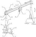
图1是本发明方法所基于的轨道线路龙门吊运装置一种具体实施例中龙门吊的立体结构示意图;Fig. 1 is the three-dimensional structure schematic diagram of the gantry crane in a specific embodiment of the rail line gantry hoisting device on which the method of the present invention is based;
图2是本发明方法所基于的轨道线路龙门吊运装置一种具体实施例中龙门吊的正面结构示意图;Fig. 2 is the front structure schematic diagram of the gantry crane in a specific embodiment of the rail line gantry hoisting device on which the method of the present invention is based;
图3是本发明方法所基于的轨道线路龙门吊运装置一种具体实施例中龙门吊的侧面结构示意图;Fig. 3 is the side structure schematic diagram of the gantry crane in a specific embodiment of the rail line gantry hoisting device on which the method of the present invention is based;
图4是本发明方法所基于的轨道线路龙门吊运装置一种具体实施例中龙门吊的侧面结构透视图;4 is a perspective view of the side structure of the gantry crane in a specific embodiment of the rail line gantry hoisting device on which the method of the present invention is based;
图5是本发明方法所基于的轨道线路龙门吊运装置一种具体实施例中龙门吊的结构示意俯视图;5 is a schematic top view of the structure of a gantry crane in a specific embodiment of a rail line gantry hoisting device on which the method of the present invention is based;
图6是本发明方法所基于的轨道线路龙门吊运装置一种具体实施例中吊运工装的横向结构示意图;6 is a schematic diagram of the lateral structure of a hoisting tool in a specific embodiment of the rail line gantry hoisting device on which the method of the present invention is based;
图7是本发明方法所基于的轨道线路龙门吊运装置一种具体实施例中吊运工装的纵向结构示意图;Fig. 7 is the longitudinal structural schematic diagram of the hoisting tool in a specific embodiment of the rail line gantry hoisting device on which the method of the present invention is based;
图8是本发明方法所基于的轨道线路龙门吊运装置一种具体实施例中吊运工装的立体结构示意图;8 is a schematic three-dimensional structural diagram of a hoisting tool in a specific embodiment of a rail line gantry hoisting device on which the method of the present invention is based;
图9是本发明方法所基于的轨道线路龙门吊运装置一种具体实施例中龙门吊的安装结构示意图;9 is a schematic diagram of the installation structure of a gantry crane in a specific embodiment of a rail line gantry hoisting device on which the method of the present invention is based;
图10是本发明方法所基于的轨道线路龙门群吊系统一种具体实施例中旋转安装座的结构示意简图;10 is a schematic structural diagram of a rotary mounting seat in a specific embodiment of the track line gantry group crane system on which the method of the present invention is based;
图11是本发明方法所基于的轨道线路龙门群吊系统一种具体实施例中旋转安装座的立体结构示意图;11 is a schematic three-dimensional structural diagram of a rotary mounting seat in a specific embodiment of a rail line gantry group crane system on which the method of the present invention is based;
图12是本发明方法所基于的轨道线路龙门群吊系统一种具体实施例中旋转安装座的结构示意仰视图;12 is a schematic bottom view of the structure of the rotary mounting seat in a specific embodiment of the track line gantry group crane system on which the method of the present invention is based;
图13是本发明方法所基于的轨道线路龙门群吊系统一种具体实施例中旋转安装座的侧面结构示意图;Fig. 13 is the side structure schematic diagram of the rotary mounting seat in a specific embodiment of the track line gantry group crane system on which the method of the present invention is based;
图14是本发明方法所基于的轨道线路龙门群吊系统一种具体实施例中旋转安装座在另一视角下的侧面结构示意图;14 is a schematic side view of the structure of the rotary mounting seat from another perspective in a specific embodiment of the track line gantry group crane system on which the method of the present invention is based;
图15是本发明方法所基于的轨道线路龙门群吊系统一种具体实施例中无线遥控装置的结构示意图;15 is a schematic structural diagram of a wireless remote control device in a specific embodiment of a track line gantry group crane system on which the method of the present invention is based;
图16是本发明方法所基于的轨道线路龙门群吊系统一种具体实施例在侧视视角下的结构示意图;16 is a schematic structural diagram of a specific embodiment of a rail line gantry group crane system based on the method of the present invention from a side view perspective;
图17是本发明方法所基于的轨道线路龙门群吊系统一种具体实施例在俯视视角下的结构示意图;17 is a schematic structural diagram of a specific embodiment of the track line gantry group crane system based on the method of the present invention from a top view;
图18是本发明轨道线路龙门群吊作业方法一种具体实施例中龙门吊运输步骤在侧视视角下的示意图;Fig. 18 is a schematic diagram of a gantry crane transportation step in a specific embodiment of the rail line gantry group crane operation method of the present invention from a side view perspective;
图19是本发明轨道线路龙门群吊作业方法一种具体实施例中龙门吊运输步骤在俯视视角下的示意图;19 is a schematic diagram of the transport steps of the gantry cranes in a specific embodiment of the rail line gantry group crane operation method of the present invention from a top view;
图20是本发明轨道线路龙门群吊作业方法一种具体实施例中龙门吊旋转至横向步骤在侧视视角下的示意图;20 is a schematic diagram of the step of rotating the gantry crane to the lateral direction in a specific embodiment of the rail line gantry group crane operation method of the present invention from a side view perspective;
图21是本发明轨道线路龙门群吊作业方法一种具体实施例中龙门吊旋转至横向步骤在俯视视角下的示意图;Fig. 21 is a schematic diagram of the step of rotating the gantry crane to the horizontal in a specific embodiment of the rail line gantry group crane operation method of the present invention from a top view;
图22是本发明轨道线路龙门群吊作业方法一种具体实施例中龙门吊伸缩下车步骤在侧视视角下的示意图;22 is a schematic diagram of the step of telescopically disembarking the gantry crane in a specific embodiment of the rail line gantry group crane operation method of the present invention from a side view perspective;
图23是本发明轨道线路龙门群吊作业方法一种具体实施例中龙门吊伸缩下车步骤在俯视视角下的示意图;Fig. 23 is a schematic diagram of the telescopic alighting step of the gantry crane in a specific embodiment of the rail line gantry group crane operation method of the present invention from a top view;
图24是本发明轨道线路龙门群吊作业方法一种具体实施例中新道岔起吊步骤在侧视视角下的示意图;24 is a schematic diagram of the lifting step of the new switch in a specific embodiment of the rail line gantry group lifting operation method of the present invention from a side view perspective;
图25是本发明轨道线路龙门群吊作业方法一种具体实施例中新道岔起吊步骤在俯视视角下的示意图;25 is a schematic diagram of the lifting step of a new switch in a specific embodiment of the rail line gantry group lifting operation method of the present invention from a top view;
图26是本发明轨道线路龙门群吊作业方法一种具体实施例中新道岔放置步骤在侧视视角下的示意图;26 is a schematic diagram of a new switch placement step in a specific embodiment of the track line gantry group crane operation method of the present invention from a side view perspective;
图27是本发明轨道线路龙门群吊作业方法一种具体实施例中新道岔放置步骤在俯视视角下的示意图;Figure 27 is a schematic diagram of a new switch placement step in a specific embodiment of the track line gantry crane operation method of the present invention from a top view;
图28是本发明轨道线路龙门群吊作业方法一种具体实施例中旧道岔拆除步骤在俯视视角下的示意图;Fig. 28 is a schematic diagram of the dismantling step of the old switch in a specific embodiment of the rail line gantry group crane operation method of the present invention from a top view;
图29是本发明轨道线路龙门群吊作业方法一种具体实施例中旧道岔起吊放置步骤在俯视视角下的示意图;29 is a schematic diagram of the lifting and placing steps of the old turnout in a specific embodiment of the rail line gantry group hoisting operation method of the present invention from a top view;
图30是本发明轨道线路龙门群吊作业方法一种具体实施例中新道岔安装步骤在俯视视角下的示意图;30 is a schematic diagram of the installation steps of a new switch in a specific embodiment of the rail line gantry group crane operation method of the present invention from a top view;
图31是本发明轨道线路龙门群吊作业方法一种具体实施例中旧道岔起吊步骤在侧视视角下的示意图;31 is a schematic diagram of the lifting step of the old switch in a specific embodiment of the rail line gantry group lifting operation method of the present invention from a side view perspective;
图32是本发明轨道线路龙门群吊作业方法一种具体实施例中旧道岔起吊步骤在俯视视角下的示意图;32 is a schematic diagram of the lifting step of the old turnout in a specific embodiment of the rail line gantry group lifting operation method of the present invention from a top view;
图33是本发明轨道线路龙门群吊作业方法一种具体实施例中旧道岔放置至平车步骤在俯视视角下的示意图;33 is a schematic view from a top view of a step of placing an old turnout on a flat car in a specific embodiment of the rail line gantry group crane operation method of the present invention;
图34是本发明轨道线路龙门群吊作业方法一种具体实施例中平车开行至龙门吊回收位置步骤在侧视视角下的示意图;34 is a schematic diagram of the step of driving the flat car to the recovery position of the gantry crane in a specific embodiment of the rail line gantry crane operation method of the present invention, from a side view perspective;
图35是本发明轨道线路龙门群吊作业方法一种具体实施例中平车开行至龙门吊回收位置步骤在俯视视角下的示意图;35 is a schematic view from a top view of the step of driving the flat car to the recovery position of the gantry crane in a specific embodiment of the rail line gantry group crane operation method of the present invention;
图36是本发明轨道线路龙门群吊作业方法一种具体实施例中龙门吊回收至平车步骤在侧视视角下的示意图;36 is a schematic diagram of the step of recovering the gantry crane to a flat car in a specific embodiment of the rail line gantry group crane operation method of the present invention from a side view perspective;
图37是本发明轨道线路龙门群吊作业方法一种具体实施例中龙门吊回收至平车步骤在俯视视角下的示意图;37 is a schematic view from a top view of the step of recovering the gantry crane to a flat car in a specific embodiment of the rail line gantry group crane operation method of the present invention;
图38是本发明轨道线路龙门群吊作业方法一种具体实施例中龙门吊旋转至纵向固定步骤在侧视视角下的示意图;Fig. 38 is a schematic diagram of the step of rotating the gantry crane to vertical fixing in a specific embodiment of the rail line gantry group crane operation method of the present invention, from a side view perspective;
图39是本发明轨道线路龙门群吊作业方法一种具体实施例中龙门吊旋转至纵向固定步骤在俯视视角下的示意图;39 is a schematic view from a top view of the step of rotating the gantry crane to the vertical fixing step in a specific embodiment of the rail line gantry group crane operation method of the present invention;
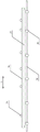
图中:1-横梁,2-滑移框,3-滑移驱动机构,4-起吊机构,5-支腿,6-螺纹筒,7-升降驱动机构,8-可调支脚,9-螺杆,10-支座,11-支腿套筒,12-电源柜,13-轴承,14-第一距离传感器,15-第二距离传感器,16-力传感器,17-倾斜传感器,18-楔形锁紧机构,19-升降座,20-回转轴承,21-固定安装座,22-锁紧座,23-导柱座,24-升降机构,25-导柱,26-锁紧机构,27-滑移机构,28-凹槽,29-止挡部,30-导向突起,31-导向槽,32-旋转驱动机构,33-吊运工装,34-道岔,35-轨道板,36-承载梁,37-安装架,38-吊环,39-吊爪,40-轨道车,41-第一运输平车,42-第二运输平车,43-动力装置,44-新道岔,45-钢轨,46-底座,47-路基,48-纵移机构,49-固定座,50-链轮,51-链条,52-锁定机构,53-安装座,54-横移支座,55-吊钩,56-旧道岔,57-无线遥控装置,58-龙门吊操作区,59-综合作业操作区,60-底板,100-龙门吊,200-旋转安装座。In the picture: 1-beam, 2-sliding frame, 3-sliding drive mechanism, 4-hoisting mechanism, 5-outrigger, 6-threaded barrel, 7-lifting drive mechanism, 8-adjustable foot, 9-screw , 10-support, 11-leg sleeve, 12-power cabinet, 13-bearing, 14-first distance sensor, 15-second distance sensor, 16-force sensor, 17-tilt sensor, 18-wedge lock Tightening mechanism, 19-lifting seat, 20-slewing bearing, 21-fixed mounting seat, 22-locking seat, 23-guide column seat, 24-lifting mechanism, 25-guide column, 26-locking mechanism, 27-slide Shifting mechanism, 28-groove, 29-stop, 30-guide protrusion, 31-guide groove, 32-rotation drive mechanism, 33-lifting tool, 34-turnout, 35-track plate, 36-bearing beam, 37-mounting frame, 38-hoisting ring, 39-lifting jaw, 40-rail car, 41-first transport flat car, 42-second transport flat car, 43-power unit, 44-new switch, 45-rail, 46 - Base, 47- Subgrade, 48- Longitudinal movement mechanism, 49- Fixed seat, 50- Sprocket, 51- Chain, 52- Locking mechanism, 53- Mounting seat, 54- Traverse support, 55- Hook, 56 -Old turnout, 57-wireless remote control device, 58-gantry crane operation area, 59-integrated operation operation area, 60-base plate, 100-gantry crane, 200-swivel mount.
具体实施方式Detailed ways
为使本发明实施例的目的、技术方案和优点更加清楚,下面将结合本发明实施例中的附图,对本发明实施例中的技术方案进行清楚、完整的描述。显然,所描述的实施例仅仅是本发明的一部分实施例,而不是全部的实施例。基于本发明中的实施例,本领域普通技术人员在没有作出创造性劳动前提下所获得的所有其它实施例,都属于本发明保护的范围。To make the purposes, technical solutions, and advantages of the embodiments of the present invention clearer, the following will clearly and completely describe the technical solutions in the embodiments of the present invention with reference to the accompanying drawings in the embodiments of the present invention. Obviously, the described embodiments are only some, but not all, embodiments of the present invention. Based on the embodiments of the present invention, all other embodiments obtained by those of ordinary skill in the art without creative efforts shall fall within the protection scope of the present invention.
以下实施例具体以铁路道岔吊运作业为例,对本发明轨道线路龙门群吊作业方法进行详细介绍,但需要特别说明的是,本发明技术方案也可以应用于其他轨道线路部件吊运作业。The following embodiments take the hoisting operation of railway turnout as an example to describe in detail the operation method of the track line gantry group hoisting operation of the present invention, but it should be noted that the technical solution of the present invention can also be applied to the hoisting operation of other track line components.
如附图1至附图39所示,给出了本发明轨道线路龙门群吊作业方法的具体实施例,下面结合附图和具体实施例对本发明作进一步说明。As shown in Figures 1 to 39, specific embodiments of the rail line gantry group crane operation method of the present invention are given, and the present invention will be further described below with reference to the accompanying drawings and specific embodiments.
实施例1Example 1
为解决现有轨道线路用起吊设备存在的技术问题,实施例1给出了一种结构简单、成本低、操作方便快捷的基于龙门吊100起吊的轨道线路龙门吊运装置,通过采用一种跨距、高度可调的智能龙门吊,能够解决现有轨道线路用起吊设备存在的技术问题。该轨道线路龙门吊运装置可利用天窗时间,采用运输平车将龙门吊100、吊运工装33,以及需要作业的对象(如:道岔)等运输至作业现场进行吊运作业。In order to solve the technical problems existing in the hoisting equipment for existing track lines,
如附图1至附图9所示,一种本发明方法所基于的轨道线路龙门吊运装置的实施例,具体包括龙门吊100,龙门吊100进一步包括:As shown in the accompanying
横梁1;
分别可活动地设置于横梁1左右两端的滑移框2,滑移框2能沿横梁1进行横向移动,以调整龙门吊100的横向跨距;The sliding
设置于横梁1上,并位于两个滑移框2之间,能沿横梁1进行横向(如附图1中W所示方向)移动的起吊机构4,以调整道岔的吊装位置;A
分别设置于两个滑移框2下方,能沿垂向(如附图1中H所示方向)进行伸缩的支腿5,以调整横梁1距离路基47的高度;The
起吊机构4上进一步设置有第一距离传感器14,第一距离传感器14用于获取起吊机构4与支腿5之间的距离,以实现多个龙门吊100对道岔34进行起吊时横向位置的对齐。在龙门吊100进行吊运作业时,第一距离传感器14获取起吊机构4与支腿5之间的距离,通过控制每个龙门吊100同侧的支腿5与起吊机构4之间的距离差值满足设定要求,以实现多个龙门吊100对道岔34进行同步起吊时的横向位置对齐。The
如附图9所示,当龙门吊100从第一运输平车41部署至铁路线路时,龙门吊100通过支腿5支撑于铁路线路两旁的路基47上,路基47上设置有底座46,底座46上设置有轨道板35,钢轨45设置于轨道板35上。龙门吊100的总高度H≥第一运输平车41的底板57距离钢轨45的轨面高度H1+钢轨45的轨面距离路基47的高度H2+起吊机构4的净空H3。其中,起吊机构4的净空H3为龙门吊100的吊钩55在最高位置时距离横梁1的距离。As shown in FIG. 9 , when the
龙门吊100的两个滑移框2或支腿5上均进一步设置有第二距离传感器15,第二距离传感器15,用于获取与相邻布置的龙门吊100之间的距离,以满足两个龙门吊100的横梁1之间的平行度要求。在第一个龙门吊100部署到位后,之后部署的龙门吊100通过设置于两个滑移框2或支腿5上的第二距离传感器15获取与相邻布置的龙门吊100之间的距离,并通过调整旋转安装座200的旋转角度以满足两个龙门吊100的横梁1之间的平行度要求。The two sliding
起吊机构4上进一步设置有力传感器16,以实现多个龙门吊100对道岔34进行起吊时的平稳性控制。当龙门吊100对新道岔44或旧道岔56开始起吊时,每个龙门吊100的起吊机构4将此时力传感器16的采集值(即刚起吊离开地面时的载荷)作为基准值。若后续起吊过程中变化值超过标准值,则通过调节起吊机构4的电机转速(可以通过控制电机电流实现),使起吊过程中起吊机构4的力传感器16采集值维持与基准值基本相当,以实现多个龙门吊100对道岔34进行同步起吊时垂向的平稳性控制。The
龙门吊100还包括滑移驱动机构3,滑移框2套设于横梁1上,滑移驱动机构3的一端设置于横梁1上,另一端与滑移框2相连。滑移框2上设置有带内螺纹的横移支座54,横梁1上设置有安装座53。滑移驱动机构3采用动力驱动丝杠机构,滑移驱动机构3的动力驱动端固定于安装座53上,滑移驱动机构3的丝杠端连接至横移支座54,通过动力驱动丝杠旋转带动滑移框2实现横移。The
如附图3和附图4所示,滑移框2内进一步设置有楔形锁紧机构18,楔形锁紧机构18位于横梁1与滑移框2之间,并包括两块相互接触的楔形滑块。通过锁定机构52穿过滑移框2后对两块楔形滑块进行压紧以实现对滑移框2位置的锁定。当两条支腿5的横向跨距调节到位后,通过楔形锁紧机构18实现滑移框2的位置锁定。As shown in FIG. 3 and FIG. 4 , the sliding
支腿5进一步包括螺纹筒6、螺杆9、支座10及支腿套筒11。螺纹筒6连接于滑移框2的下方,支腿套筒11套设于螺纹筒6的下部,支座10设置于支腿套筒11的下方。螺杆9设置于支腿套筒11内,螺杆9的上端通过螺纹与螺纹筒6相连,下端与升降驱动机构7相连。支座10内设置有升降驱动机构7,通过升降驱动机构7带动螺杆9旋转使螺纹筒6上下移动,实现支腿5的伸缩功能。The
支腿5的下部进一步设置有可调支脚8,通过可调支脚8能实现对支腿5及龙门吊100的调平功能。横梁1上设置有倾斜传感器17,龙门吊100从第一运输平车41上卸载后,通过倾斜传感器17获取龙门吊100的倾斜状态数据,并通过对可调支脚8进行微调实现横梁1的调平。The lower part of the
龙门吊100主要由工字型的横梁1、滑移伸缩的支腿5、起吊机构(葫芦吊)4、滑移机构(包括滑移框2及滑移驱动机构3)、楔形锁紧机构18,以及电源柜12等组成。支腿5通过上方的滑移框2滑套在工型的横梁1上,滑移框2上有带螺纹的板(横移支座54)与滑移驱动机构3的螺纹杆相连。滑移驱动机构3由马达或电机驱动丝杠旋转实现滑移,并通过安装座53固定在横梁2上。滑移框3内设置有楔形锁紧机构18,当横向跨距调节到位后,通过锁定机构52(采用马达或电机驱动丝杠的结构形式)可以完成锁定。滑移框2的下方焊接了螺纹筒6,螺纹筒6与螺杆9通过螺纹连接。螺杆9的下端为升降驱动机构7,采用马达或电机驱动,并通过轴承13固定于支腿的支架上。当驱动螺旋杆旋转就可以使螺纹筒上下移动,实现支腿的伸缩功能。支架的底端设有螺纹可调支脚,支脚通过销轴与支架相连,应对地面不平整环境。The
如附图7和附图8所示,轨道线路龙门吊运装置还包括吊运工装33,吊运工装33进一步包括承载梁36、安装架37、吊环38及吊爪39。起吊机构4包括能沿垂向进行升降移动的吊钩55,吊环38设置于承载梁36的上部,吊钩55与吊环38相连。安装架37设置于承载梁36的下部,吊爪39沿线路方向(如附图7和附图8中L所示方向)设置于安装架37的左右两侧。吊运工装33上端吊环38的可以通过吊带或挂钩与多个龙门吊100的吊钩55相连,下端通过多个吊点与道岔34相连,如附图6所示。其中,安装架37具有纵向可移动功能,可以在道岔34起吊后沿线路方向相对于承载梁36前后移动,以解决道岔34准确定位的问题。As shown in FIGS. 7 and 8 , the rail line gantry hoisting device further includes a
在龙门吊100进行吊运作业时,通过吊爪39起吊道岔34。当道岔34吊起后,再通过安装架37在承载梁36上沿线路方向前后移动,从而将道岔34吊运至指定的纵向位置。安装架37与承载梁36可活动地连接,承载梁36沿线路方向的两端均设置有链轮50,两个链轮50之间通过链条51连接。链条51与安装架37连接,通过纵移机构48驱动其中一个链轮50转动,链轮50转动带动链条51沿线路方向前后移动,从而实现安装架37的纵向(如附图7和附图8中L所示方向)移动,以解决道岔34准确定位的问题。When the
实施例1描述的轨道线路龙门吊运装置,其支腿5在垂向可伸缩,并可在横梁1上滑移,以调节龙门吊100的跨度及高度,以适应不同的现场条件和不同尺寸道岔34的更换。支腿5采用可旋转和调平机构,并采用油缸或电动丝杠等方式实现。起吊机构4可以采用葫芦吊或者其它吊具。The rail line gantry hoisting device described in
实施例2Example 2
为了解决现有铁路线路,尤其是高铁无砟轨道道岔部件更换的诸多问题,实施例2给出了一种结构简单、成本低、操作方便快捷,可通过轨道平车运输至铁路现场的多个智能龙门吊组成的群吊系统,采用群吊的方法平稳吊运铁路线路上的重物部件。当多个龙门吊100从轨道平车卸载并按距离要求完成部署后,在线路部件起吊过程中通过群吊控制解决多个龙门吊100起吊的同步性以及吊运过程中的平稳性问题。该轨道线路龙门群吊系统利用天窗时间,采用运输平车将龙门吊100、吊运工装33及新道岔44运输至作业现场,并放置于适当位置后进行新旧道岔的起吊和更换作业,再将旧道岔56运离作业现场。当起吊道岔部件超大尺寸物件时,采用多个龙门吊进行起吊,通过对智能龙门吊群吊作业的合理控制,达到平稳作业的目的。In order to solve many problems in the replacement of existing railway lines, especially high-speed rail ballastless track turnout components,
如附图16和附图17所示,一种本发明方法所基于的轨道线路龙门群吊系统的实施例,具体包括:在作业状态下沿线路方向间隔布置于铁路线路上的若干个如实施例1所述的龙门吊100,龙门吊100跨设于铁路线路两侧的路基47上。As shown in FIG. 16 and FIG. 17 , an embodiment of a rail line gantry group crane system on which the method of the present invention is based specifically includes: in an operating state, several In the
龙门吊100在运输状态下设置于第一运输平车41上,系统还包括:The
轨道车40、第一运输平车41及第二运输平车42;
在运输状态下设置于第一运输平车41上,用于对龙门吊100进行固定的旋转安装座200;The
在运输状态下设置于第二运输平车42上的吊运工装33及道岔34。The
在作业状态下,吊运工装33的上端通过吊环38与多个龙门吊100的吊钩55相连,吊运工装33的下端通过多个吊爪39与道岔34相连。在作业时,当若干个龙门吊100部署至合适位置后,通过吊运工装33起吊道岔34。在道岔34起吊后,再通过牵引机构40驱动安装架37在承载梁36上沿线路方向前后移动,从而将道岔34吊运至指定的纵向位置。In the working state, the upper end of the
运输采用轨道车40临时拖运,一台改装平车(即第一运输平车41)运输多个龙门吊100,两台普通平车(即第二运输平车42)运输新旧道岔,如附图15和附图16所示。轨道车40、第一运输平车41或第二运输平车42上进一步设置有动力装置43,用于为旋转安装座200提供动力。动力装置43可采用不同类型:电池驱动或发电机驱动,执行机构可采用电驱动或液压驱动等。可采用每个旋转安装座200单独驱动或集中统一动力驱动模式。The transportation adopts the
在作业状态下,若干个龙门吊100沿线路方向(如附图15和附图16中L所示方向)间隔布置,吊运工装33的上部通过吊环38与多个龙门吊100的吊钩55相连,吊运工装33的下部通过多个吊爪39与道岔34相连。在道岔34起吊后,通过纵移机构48驱动安装架37相对于承载梁36沿线路方向进行前后移动,以实现道岔34在纵向的准确定位。In the working state,
实施例2描述的道岔更换系统采用多个(一般3至5个)龙门吊100的群吊方式,将3-5个龙门吊100、吊运工装33及新道岔44通过轨道平车(包括轨道车40、第一运输平车41及第二运输平车42)运输至作业现场,多个龙门吊100按位置和顺序依次下车至指定位置。然后,通过群吊和专用的吊运工装33将新道岔44卸车并放置于龙门吊100的下方。再拆卸旧道岔56,并通过龙门吊100进行新旧道岔的更换。待线路恢复后,旧道岔56被吊运至第二运输平车42上,多个龙门吊100再分别依次上车并固定驶离。The switch replacement system described in
实施例3Example 3
如附图10至附图14所示,一种应用于实施例2所述轨道板更换系统的旋转固定装置200的实施例,具体包括:As shown in FIG. 10 to FIG. 14 , an embodiment of the
固定于第一运输平车41上的固定安装座21;the fixed mounting
用于固定安装龙门吊100的升降座19,升降座19能相对于固定安装座21进行升降运动,以实现龙门吊100上下第一运输平车41;The lifting
设置于固定安装座21与升降座19之间的回转轴承20,通过回转轴承20使得升降座19能相对于固定安装座21进行水平旋转运动,以调整龙门吊100的安装方向。The slewing
实施例2描述的旋转固定装置200能够将多个龙门吊100固定于轨道平车上,在确保不超车辆运输限界的情况下,通过轨道平车将多个龙门吊100运输,并部署至作业现场,进行起吊作业,再进行回收。The
当处于运输状态时,龙门吊100呈纵向固定于升降座19上。当处于部署状态时,通过回转轴承20进行旋转使龙门吊100调整至横向布置。When in the transport state, the
旋转固定装置200还包括设置于升降座19之上的锁紧座22,锁紧座22上设置有若干用于固定龙门吊100的凹槽28,凹槽28的数量根据龙门吊100的尺寸决定,一般为2至3对。旋转固定装置200还包括设置于回转轴承20之上的导柱座23,回转轴承20的内圈与导柱座23固定安装,回转轴承20的外圈与固定安装座21固定安装。导柱座23上安装有导柱25,导柱25穿过开设于升降座19上的通孔,当升降机构24进行伸缩运动时,由导柱25实现升降座19的升降导向。旋转固定装置200还包括旋转驱动机构32,旋转驱动机构32的一端固定安装于固定安装座21上,另一端通过齿轮旋转驱动外圈带有齿轮的回转轴承20实现旋转功能。The
旋转固定装置200还包括升降机构24,升降机构24的一端固定安装于导柱座23上,另一端连接至升降座19,通过升降机构24的伸缩运动实现龙门吊100的升降功能。在锁紧座22的侧面并靠近每一对凹槽28的位置均设置有锁紧机构26,当龙门吊100的横梁1固定在凹槽28中后,通过锁紧机构26对横梁1的压紧将龙门吊100锁定安装在凹槽28中。锁紧机构26可采用油缸直接侧面压紧,或采用杠杆结构进行压紧。两套锁紧机构26通过油缸将龙门吊100的横梁1紧压在凹槽28内,从而固定龙门吊100。其中,升降座19及锁紧座22的中部中空,以容纳龙门吊100的起吊机构4。The
在锁紧座22上彼此相对地设置有两个滑移机构27,在升降座19上与滑移机构27相对的位置设置有止挡部29,滑移机构27的活动端与止挡部29相接触。当其中一个滑移机构27的活动端拉伸,另一个滑移机构27的活动端收缩,从而带动锁紧座22相对于升降座19沿滑移机构27运动方向进行滑移。在升降座19上沿滑移机构27运动方向彼此相对地开设有两个导向突起30,在锁紧座22上设置有两个与导向突起30分别对应的导向槽31。导向槽31滑套在导向突起30上,对锁紧座22与升降座19之间的相对滑移进行导向。Two sliding
固定安装座21的底座通过螺栓与第一运输平车41的底板56连接,最上面使用螺栓安装外圈带齿轮的回转轴承20,在固定安装座21安装的旋转驱动的齿轮驱动回转轴承20实现旋转功能。回转轴承20的内圈上部通过螺栓安装导柱座23,导柱座23的上部通过过盈配合安装两根导柱25。导柱座23上固定升降机构24(可以具体采用升降油缸、气缸或电缸),升降机构24的活塞杆与升降座19相连接,升降座19又套设在两根导柱25上,升降机构24伸缩就可以实现升降功能。升降座19上设有两个导向突起30,起导轨功能。锁紧座22上设有两个导向槽31,导向槽31滑套在两个导向凸起30上。在锁紧座22上安装有两个滑移机构27(可以具体采用升降油缸、气缸或电缸),滑移机构27的活塞杆与升降座19上的止挡部29相连接,两个滑移机构27分别一伸一缩,就可以实现整个锁紧座22在升降座19上的滑移。The base of the fixed mounting
旋转固定装置200由带凹槽28的锁紧座22、升降座19、回转轴承20及固定安装座21等组成。升固定安装座21固定于第一运输平车41的底板60上,并通过螺栓连接。旋转固定装置200采用电池、发电机或平车供电。运输时,龙门吊100被锁紧机构26锁定压紧在凹槽28中。回转轴承20通过马达或电机驱动旋转,升降座19可采用油缸完成升降动作。工作时,旋转固定装置200可通过升降座19使龙门吊100提升或下降,驱动旋转后,龙门吊100就可以实现不同角度的水平旋转,到达指定位置后,释放锁紧机构26,龙门吊100就可以从凹槽28中完成脱离。将龙门吊100在第一运输平车41上顺向安装的位置作为回转轴承20旋转的起始点,在其顺时针旋转90°时作为终止点,在起始点和终止点均设置有位置传感器,旋转到位后即停止动作并锁定。The
当处于运输状态时,龙门吊100被纵向锁定安装于固定安装座21的凹槽28中,如附图15所示。当到达作业现场后,先通过升降机构24带动龙门吊100上升至最高点后,再通过旋转驱动机构32带动龙门吊100旋转至横向,升降机构24再带动龙门吊100下降至作业面。当龙门吊100的支腿5下降至指定位置时,锁紧机构26释放,龙门吊100从凹槽28中脱出,以实现龙门吊100的作业部署。When in the transport state, the
实施例4Example 4
实施例4给出的轨道线路龙门群吊作业方法,根据吊装对象的需要,将若干个龙门吊100,及吊运工装33等其它物料通过轨道平车运输至作业现场。多个龙门吊100按位置和顺序自动卸载并部署到位,轨道平车驶离,然后可以进行吊运作业。通过对群吊的综合控制,完成吊运作业后,平车进入,龙门吊100再回收上车,固定在平车上驶离。在本实施例中,省去了其它例如:龙门吊支撑点确认、支撑点整平、钢轨扣件拆卸及钢轨切割焊接打磨调平等辅助工序流程,以下具体以岔心更换流程为例对本发明轨道线路龙门群吊作业方法进行详细说明。In the operation method of the rail line gantry group crane given in Example 4,
由于每个龙门吊100之间的距离较长,因此采用无线遥控装置57通过集中无线遥控的方法对每个龙门吊100的动作进行协调控制。在每个龙门吊100均设有含控制系统的电源柜12,带信号接收和信号反馈功能。如附图15所示,无线遥控装置57的操作界面包括龙门吊操作区58及综合作业操作区59,并带有信号接收和发射功能,同时配备龙门吊100的各动作按钮。群吊的同步控制主要是两方面:同步横向吊运及同步垂向吊运。多个龙门吊100的垂向同步等距上升和横向等距移动均依赖于龙门吊100上安装的传感器,以及旋转安装座200将对龙门吊100纵向放置后使龙门吊100之间的平行度基本满足要求。Since the distance between each
附图18至附图39所示,一种本发明轨道线路龙门群吊作业方法的实施例,具体包括以下步骤:As shown in Fig. 18 to Fig. 39, an embodiment of the operation method of the rail line gantry group crane of the present invention specifically includes the following steps:
S100)在作业之前,根据吊装对象及环境条件,做好吊装方案,包括需要多少个龙门吊100,并在每个龙门吊100放置的位置进行标记;每个固定龙门吊100的旋转安装座200的旋转起始点传感器位置先进行调校,使每个龙门吊100的横梁1平行;每个旋转安装座200旋转90°的旋转终点传感器位置调校,当每个龙门吊100旋转90°后横梁1平行;S100) Before the operation, according to the hoisting object and environmental conditions, make a hoisting plan, including how
S101)若干个龙门吊100通过旋转安装座200呈纵向(如附图18和附图19中L所示方向)固定于第一运输平车41上(以适应车辆限界),新道岔44及吊运工装33放置于第二运输平车42上,通过轨道车40运输至作业现场的指定位置,如附图18和附图19所示;S101)
S102)通过轨道车40牵引第一运输平车41,并利用旋转安装座200将龙门吊100依次部署至线路的指定位置;S102) pulling the first transport
步骤S102)进一步包括:Step S102) further includes:
S1021)轨道车40牵引第一运输平车41移动至第一个龙门吊100的放置位置,旋转安装座200旋转90°至龙门吊100与线路方向垂直,此时龙门吊100通过旋转安装座200呈横向(如附图21中W所示方向)固定于第一运输平车41上,如附图20和附图21所示;S1021) The
S1022)龙门吊100的支腿5沿横梁1移动至指定位置,旋转安装座200带动龙门吊100下降;支腿5向下伸长至接近地面,旋转安装座200对龙门吊100的锁定释放,支腿5继续伸长并进行调平,完成一个龙门吊100的部署;S1022) The
S1023)轨道车40牵引第一运输平车41顺序移动,重复执行步骤S1022),直到所有的龙门吊100部署至指定位置,如附图22和附图23所示;S1023) The
S103)轨道车40牵引第二运输平车42移动至指定位置,将吊运工装33与若干个龙门吊100的起吊机构4进行连挂以实现群吊作业,吊运工装33移动并起吊新道岔44,如附图24和附图25所示;S103) The
S104)轨道车40牵引第一运输平车41、第二运输平车42驶离道岔更换作业区,通过若干个龙门吊100进行群吊将新道岔44横向移动至靠支腿5的一侧放置,如附图26和附图27所示。S104) The
在步骤S104)之后还包括以下过程:The following process is also included after step S104):
S105)切割钢轨45、拆除扣件,并将旧道岔56拆除;S105) cutting the
S106)通过龙门吊100将吊运工装33移动至旧道岔56处并挂连起吊,将旧道岔56放置于靠龙门吊100另一侧的支腿5,如附图29所示;S106) Move the
S107)通过龙门吊100将吊运工装33移动至新道岔44处并挂连起吊,将新道岔44放置于旧道岔56的位置,如附图30和附图31所示。若有偏差,可通过移动吊运工装33的安装架37进行位置精确调整。然后将新道岔44与钢轨45进行焊接,安装扣件,线路完成恢复。S107) Move the
在步骤S109)之后还包括以下过程:After step S109), the following process is also included:
S108)通过龙门吊100将吊运工装33移动至旧道岔56处并挂连起吊;S108) Move the
S109)轨道车40牵引第二运输平车42驶入;S109) the
S110)通过吊运工装33将旧道岔56移动并放置于第二运输平车42的指定位置,如附图32和附图33所示。S110) Move the
在步骤S112)之后还包括以下过程:The following process is also included after step S112):
S111)轨道车40牵引第一运输平车41移动至处于最末位置龙门吊100的下方,龙门吊100的横梁1对准旋转安装座200的凹槽28位置,如附图34和附图35所示;S111) The
S112)龙门吊100的支腿5收缩至横梁1进入旋转安装座200的凹槽28中并固定;S112) The
S113)龙门吊100的支腿5继续收缩至起始位置,支腿5沿横梁1移动至起始位置,此时龙门吊100通过旋转安装座200呈横向(如附图35中W所示方向)固定于第一运输平车41上;S113) The
S114)重复执行步骤S111)~S113),完成其余龙门吊100的回收过程,如附图36和附图37所示;S114) Repeat steps S111) to S113) to complete the recovery process of the remaining
S115)旋转安装座200旋转至龙门吊100呈纵向(如附图38和附图39所示中L所示方向)固定,轨道车40牵引第一运输平车41、第二运输平车42驶离,如附图38和附图39所示。S115) The
在新道岔44或旧道岔56的吊运作业过程中,对龙门吊100起吊新道岔44进行横向移动及垂向移动同步控制。During the hoisting operation of the
步骤S102)还进一步包括:Step S102) also further includes:
在第一个龙门吊100部署到位后,之后部署的龙门吊100通过设置于两个滑移框2或支腿5上的第二距离传感器15获取与相邻布置的龙门吊100之间的距离,并通过调整旋转安装座200的旋转角度以满足两个龙门吊100的横梁1之间的平行度要求。After the
在起吊机构4上设置第一距离传感器14,在龙门吊100进行吊运作业时,第一距离传感器14获取起吊机构4与支腿5之间的距离,通过控制每个龙门吊100同侧的支腿5与起吊机构4之间的距离差值满足设定要求,以实现多个龙门吊100对道岔34进行同步起吊时的横向位置对齐。A
在支腿5的下部设置可调支脚8,通过可调支脚8实现对支腿5及龙门吊100的调平功能。在横梁1上设置倾斜传感器17,在龙门吊100部署过程中通过倾斜传感器17获取龙门吊100的倾斜状态数据,并通过对可调支脚8进行微调实现横梁1的调平。An
在起吊机构4上设置力传感器16,当龙门吊100对新道岔44或旧道岔56开始起吊时,每个龙门吊100的起吊机构4将此时力传感器16的采集值作为基准值。若后续起吊过程中变化值超过标准值,则通过调节起吊机构4的电机转速,使起吊过程中起吊机构4的力传感器16采集值维持与基准值基本相当,以实现多个龙门吊100对道岔34进行同步起吊时垂向的平稳性控制。A
吊运工装33包括承载梁36、安装架37、吊环38及吊爪39。起吊机构4包括能沿垂向进行升降移动的吊钩55,所述吊环38设置于承载梁36的上部,吊钩55与吊环38相连。安装架37设置于承载梁36的下部,吊爪39沿线路方向设置于安装架37的左右两侧。安装架37与承载梁36可活动地连接,承载梁36沿线路方向的两端均设置有链轮50,两个链轮50之间通过链条51连接。链条51与安装架37连接,通过纵移机构48驱动其中一个链轮50转动,链轮50转动带动链条51沿线路方向运动,从而实现安装架37的纵向移动。The
在本申请的描述中,需要说明的是,当元件被称为“固定于”或“设置于”另一个元件上,它可以直接在另一个元件上或者间接设置在另一个元件上;当一个元件被称为是“连接于”另一个元件,它可以是直接连接到另一个元件或间接连接至另一个元件上。In the description of this application, it should be noted that when an element is referred to as being "fixed" or "disposed on" another element, it can be directly or indirectly disposed on the other element; when an element is referred to as being "fixed" or "disposed on" another element An element is referred to as being "connected to" another element, and it can be directly connected to the other element or indirectly connected to the other element.
需要理解的是,术语“中心”、“纵向”、“横向”、“长度”、“宽度”、“厚度”、“上”、“下”、“前”、“后”、“左”、“右”、“竖直”、“水平”、“顶”、“底”“内”、“外”等指示的方位或位置关系为基于附图所示的方位或位置关系,仅是为了便于描述本申请和简化描述,而不是指示或暗示所指的装置或元件必须具有特定的方位、以特定的方位构造和操作,因此不能理解为对本申请的限制。It is to be understood that the terms "center", "longitudinal", "lateral", "length", "width", "thickness", "top", "bottom", "front", "rear", "left", The orientation or positional relationship indicated by "right", "vertical", "horizontal", "top", "bottom", "inside", "outside", etc. is based on the orientation or positional relationship shown in the drawings, and is only for convenience Describe the application and simplify the description without indicating or implying that the referred device or element must have a particular orientation, be constructed and operate in a particular orientation, and therefore should not be construed as limiting the application.
此外,术语“第一”、“第二”仅用于描述目的,而不能理解为指示或暗示相对重要性或者隐含指明所指示的技术特征的数量。由此,限定有“第一”、“第二”的特征可以明示或者隐含地包括一个或者更多个该特征。在本申请的描述中,“多个”、“若干个”的含义是两个或两个以上,除非另有明确具体的限定。In addition, the terms "first" and "second" are only used for descriptive purposes, and should not be construed as indicating or implying relative importance or implying the number of indicated technical features. Thus, a feature defined as "first" or "second" may expressly or implicitly include one or more of that feature. In the description of the present application, "plurality" and "several" mean two or more, unless otherwise expressly and specifically defined.
须知,本说明书附图所绘示的结构、比例、大小等,均仅用以配合说明书所揭示的内容,以供熟悉此技术的人士了解与阅读,并非用以限定本申请可实施的限定条件,故不具技术上的实质意义,任何结构的修饰、比例关系的改变或大小的调整,在不影响本申请所能产生的功效及所能达成的目的下,均应仍落在本申请所揭示的技术内容能够涵盖的范围内。It should be noted that the structures, proportions, sizes, etc. shown in the drawings of this specification are only used to cooperate with the contents disclosed in the specification for the understanding and reading of those who are familiar with this technology, and are not used to limit the conditions that the application can implement. Therefore, it has no technical substantive significance. Any structural modification, proportional relationship change or size adjustment should still fall within the scope of the disclosure in this application, without affecting the effect that the application can produce and the purpose that can be achieved. The technical content can cover the scope.
通过实施本发明具体实施例描述的轨道线路龙门群吊作业方法的技术方案,能够产生如下技术效果:By implementing the technical scheme of the rail line gantry group crane operation method described in the specific embodiment of the present invention, the following technical effects can be produced:
(1)本发明具体实施例描述的轨道线路龙门群吊作业方法,龙门吊具备支腿横移、升降、调平功能,支腿横向跨度间距、距离地面高度、起吊位置及高度均可实现精密调节,能够满足不同线路地面工况需求的功能,且龙门吊高度可调,起吊过程中无碰触接触网的风险,便于一致性控制操作和维护;(1) The operation method of the rail line gantry group crane described in the specific embodiment of the present invention, the gantry crane has the functions of lateral movement, lifting and leveling of the outriggers, and the lateral span spacing of the outriggers, the height from the ground, the lifting position and the height can be precisely adjusted. , can meet the needs of different line ground conditions, and the height of the gantry crane is adjustable, there is no risk of touching the catenary during the lifting process, and it is convenient for consistent control operation and maintenance;
(2)本发明具体实施例描述的轨道线路龙门群吊作业方法,既适用于整组道岔更换也适应于单根尖轨、岔心等的更换,通过多个龙门吊组合能够实现对各种不同长度线路部件的搬运、放置、位置调整及更换;且线路部件更换不会占用邻线空间,操作灵活,不存在作业安全风险,能够很好地适应复杂线路工况下的作业需求;(2) The operation method of gantry group cranes for track lines described in the specific embodiments of the present invention is suitable for the replacement of the entire group of turnouts as well as the replacement of single pointed rails, switch cores, etc., through the combination of multiple gantry cranes, various The handling, placement, position adjustment and replacement of long line components; and the replacement of line components will not occupy the adjacent line space, the operation is flexible, there is no operation safety risk, and it can well adapt to the operation requirements under complex line conditions;
(3)本发明具体实施例描述的轨道线路龙门群吊作业方法,龙门吊结构简单、可靠性高、便于维护检修、制造成本低、作业效率高,龙门吊占用空间小、质量轻,放置及回收可以通过升降平台实现,龙门吊的运输、放置、作业、回收均可采用无线控制,一体化和智能化程度高,作业效率进一步提高;(3) The operation method of the rail line gantry group crane described in the specific embodiment of the present invention has the advantages of simple structure, high reliability, easy maintenance and repair, low manufacturing cost, high operation efficiency, small occupied space and light weight, and can be placed and recycled. Through the lifting platform, the transportation, placement, operation and recycling of the gantry crane can be controlled by wireless, with a high degree of integration and intelligence, and the operation efficiency is further improved;
(4)本发明具体实施例描述的轨道线路龙门群吊作业方法,龙门吊的横梁倾斜度通过倾斜传感器反馈,通过微调支腿高度,使横梁倾斜度达到要求;通过在龙门吊的两支腿或滑移框安装测距传感器,可以保证前后龙门吊部署的平行度要求;起吊机构设置横向位置传感器,使得每个吊钩在横向的位置一致;起吊机构转轴上设置力传感器,可满足同步起吊的平稳性要求。(4) The operation method of the rail line gantry group crane described in the specific embodiment of the present invention, the inclination of the beam of the gantry crane is fed back by the inclination sensor, and the height of the outrigger is fine-tuned to make the inclination of the beam meet the requirements; The distance measuring sensor is installed on the frame shifting, which can ensure the parallelism requirements of the front and rear gantry cranes; the hoisting mechanism is equipped with a lateral position sensor, so that the horizontal position of each hook is consistent; the force sensor is set on the rotating shaft of the hoisting mechanism, which can meet the stability of synchronous lifting Require.
本说明书中各个实施例采用递进的方式描述,每个实施例重点说明的都是与其它实施例的不同之处,各个实施例之间相同相似部分互相参见即可。The various embodiments in this specification are described in a progressive manner, and each embodiment focuses on the differences from other embodiments, and the same and similar parts between the various embodiments can be referred to each other.
以上所述,仅是本发明的较佳实施例而已,并非对本发明作任何形式上的限制。虽然本发明已以较佳实施例揭示如上,然而并非用以限定本发明。任何熟悉本领域的技术人员,在不脱离本发明的精神实质和技术方案的情况下,都可利用上述揭示的方法和技术内容对本发明技术方案做出许多可能的变动和修饰,或修改为等同变化的等效实施例。因此,凡是未脱离本发明技术方案的内容,依据本发明的技术实质对以上实施例所做的任何简单修改、等同替换、等效变化及修饰,均仍属于本发明技术方案保护的范围。The above descriptions are only preferred embodiments of the present invention, and do not limit the present invention in any form. Although the present invention has been disclosed above with preferred embodiments, it is not intended to limit the present invention. Any person skilled in the art, without departing from the spirit and technical solutions of the present invention, can make many possible changes and modifications to the technical solutions of the present invention by using the methods and technical contents disclosed above, or modify them to be equivalent. Variant equivalent embodiments. Therefore, any simple modification, equivalent replacement, equivalent change and modification made to the above embodiments according to the technical essence of the present invention without departing from the content of the technical solution of the present invention still belong to the protection scope of the technical solution of the present invention.
Claims (12)
Priority Applications (1)
| Application Number | Priority Date | Filing Date | Title |
|---|---|---|---|
| CN202210493448.6A CN114684709B (en) | 2022-05-07 | 2022-05-07 | A method for operating a gantry crane group on a track line |
Applications Claiming Priority (1)
| Application Number | Priority Date | Filing Date | Title |
|---|---|---|---|
| CN202210493448.6A CN114684709B (en) | 2022-05-07 | 2022-05-07 | A method for operating a gantry crane group on a track line |
Publications (2)
| Publication Number | Publication Date |
|---|---|
| CN114684709A true CN114684709A (en) | 2022-07-01 |
| CN114684709B CN114684709B (en) | 2025-02-11 |
Family
ID=82145312
Family Applications (1)
| Application Number | Title | Priority Date | Filing Date |
|---|---|---|---|
| CN202210493448.6A Active CN114684709B (en) | 2022-05-07 | 2022-05-07 | A method for operating a gantry crane group on a track line |
Country Status (1)
| Country | Link |
|---|---|
| CN (1) | CN114684709B (en) |
Cited By (1)
| Publication number | Priority date | Publication date | Assignee | Title |
|---|---|---|---|---|
| CN118145398A (en) * | 2024-04-23 | 2024-06-07 | 国网四川省电力公司经济技术研究院 | A highly efficient laying-out and replacing device for transmission line reels and an operating method thereof |
Citations (5)
| Publication number | Priority date | Publication date | Assignee | Title |
|---|---|---|---|---|
| EP0898016A2 (en) * | 1997-08-13 | 1999-02-24 | BWG Butzbacher Weichenbau Gesellschaft mbH & Co. KG | Method and device for the transport of a section of track |
| CN203950150U (en) * | 2014-04-29 | 2014-11-19 | 陕西江丰建筑工程有限公司 | One population hangs synchronous control system |
| CN204343117U (en) * | 2014-11-13 | 2015-05-20 | 宋谦 | A kind of lifting control device of overlength rail |
| CN107777548A (en) * | 2017-11-09 | 2018-03-09 | 中铁上海工程局集团有限公司 | The hundred meters long rail lifting straddle truck fixing device of subway route and fixing means |
| CN114408756A (en) * | 2022-02-18 | 2022-04-29 | 国家电网有限公司特高压建设分公司 | Gantry crane system for GIL installation |
-
2022
- 2022-05-07 CN CN202210493448.6A patent/CN114684709B/en active Active
Patent Citations (5)
| Publication number | Priority date | Publication date | Assignee | Title |
|---|---|---|---|---|
| EP0898016A2 (en) * | 1997-08-13 | 1999-02-24 | BWG Butzbacher Weichenbau Gesellschaft mbH & Co. KG | Method and device for the transport of a section of track |
| CN203950150U (en) * | 2014-04-29 | 2014-11-19 | 陕西江丰建筑工程有限公司 | One population hangs synchronous control system |
| CN204343117U (en) * | 2014-11-13 | 2015-05-20 | 宋谦 | A kind of lifting control device of overlength rail |
| CN107777548A (en) * | 2017-11-09 | 2018-03-09 | 中铁上海工程局集团有限公司 | The hundred meters long rail lifting straddle truck fixing device of subway route and fixing means |
| CN114408756A (en) * | 2022-02-18 | 2022-04-29 | 国家电网有限公司特高压建设分公司 | Gantry crane system for GIL installation |
Cited By (1)
| Publication number | Priority date | Publication date | Assignee | Title |
|---|---|---|---|---|
| CN118145398A (en) * | 2024-04-23 | 2024-06-07 | 国网四川省电力公司经济技术研究院 | A highly efficient laying-out and replacing device for transmission line reels and an operating method thereof |
Also Published As
| Publication number | Publication date |
|---|---|
| CN114684709B (en) | 2025-02-11 |
Similar Documents
| Publication | Publication Date | Title |
|---|---|---|
| DE212021000006U1 (en) | Road to rail dual purpose track laying machine for urban rail transport projects | |
| CN114684721A (en) | Rail circuit gantry crane transporting device and group crane system | |
| CN114941263B (en) | Switch replacing operation method | |
| CN111675112B (en) | A height-adjustable bridge pier hoisting machine, construction method and overpass method | |
| CN114701954A (en) | Switch replacing device and system | |
| CN114715797A (en) | Track slab replacing device and system | |
| CN114772464A (en) | A wireless control and gantry hoisting system for rail line gantry hoisting | |
| WO2022001169A1 (en) | Highway-railway dual-purpose track-laying machine for urban rail transit engineering | |
| CN114703705B (en) | Intelligent control system for gantry lifting of railway line | |
| CN110341732B (en) | Overhead contact system overhauls operation car and auxiliary device thereof | |
| CN109577676B (en) | Intelligent cantilever beam dismounting device and dismounting method thereof | |
| CN103787203B (en) | For installing the bracing frame of precast beam jack | |
| CN218665091U (en) | Track circuit portal crane transporting device and group crane system | |
| CN114808567A (en) | Railway line component replacement gantry crane device and operation method thereof | |
| CN114673035B (en) | Track slab replacement operation method | |
| CN217921146U (en) | Switch replacing device and system | |
| CN203602254U (en) | Support frame for installing precast beam jack | |
| CN114684709B (en) | A method for operating a gantry crane group on a track line | |
| US20220281723A1 (en) | Outrigger Pad Hoist Apparatus | |
| CN111719358A (en) | A dual-purpose track laying machine for urban rail transit engineering and its use method | |
| CN213059940U (en) | Pier hoisting machine with adjustable height | |
| CN118908057B (en) | Multifunctional combined gantry crane system and installation and use method thereof | |
| CN110329287B (en) | Overhead contact system overhauls operation car and auxiliary device thereof | |
| CN114873513B (en) | Gantry crane rotation fixing operation method | |
| CN219384510U (en) | Telescopic lifting beam for monorail crane |
Legal Events
| Date | Code | Title | Description |
|---|---|---|---|
| PB01 | Publication | ||
| PB01 | Publication | ||
| SE01 | Entry into force of request for substantive examination | ||
| SE01 | Entry into force of request for substantive examination | ||
| GR01 | Patent grant | ||
| GR01 | Patent grant |