CN114666690A - Leading sound module and head-mounted display device - Google Patents
Leading sound module and head-mounted display device Download PDFInfo
- Publication number
- CN114666690A CN114666690A CN202210284533.1A CN202210284533A CN114666690A CN 114666690 A CN114666690 A CN 114666690A CN 202210284533 A CN202210284533 A CN 202210284533A CN 114666690 A CN114666690 A CN 114666690A
- Authority
- CN
- China
- Prior art keywords
- sound
- rotating member
- sound guide
- guide module
- rotating
- Prior art date
- Legal status (The legal status is an assumption and is not a legal conclusion. Google has not performed a legal analysis and makes no representation as to the accuracy of the status listed.)
- Granted
Links
Images




Classifications
-
- H—ELECTRICITY
- H04—ELECTRIC COMMUNICATION TECHNIQUE
- H04R—LOUDSPEAKERS, MICROPHONES, GRAMOPHONE PICK-UPS OR LIKE ACOUSTIC ELECTROMECHANICAL TRANSDUCERS; ELECTRIC HEARING AIDS; PUBLIC ADDRESS SYSTEMS
- H04R1/00—Details of transducers, loudspeakers or microphones
- H04R1/02—Casings; Cabinets ; Supports therefor; Mountings therein
-
- G—PHYSICS
- G02—OPTICS
- G02B—OPTICAL ELEMENTS, SYSTEMS OR APPARATUS
- G02B27/00—Optical systems or apparatus not provided for by any of the groups G02B1/00 - G02B26/00, G02B30/00
- G02B27/01—Head-up displays
- G02B27/017—Head mounted
-
- H—ELECTRICITY
- H04—ELECTRIC COMMUNICATION TECHNIQUE
- H04R—LOUDSPEAKERS, MICROPHONES, GRAMOPHONE PICK-UPS OR LIKE ACOUSTIC ELECTROMECHANICAL TRANSDUCERS; ELECTRIC HEARING AIDS; PUBLIC ADDRESS SYSTEMS
- H04R1/00—Details of transducers, loudspeakers or microphones
- H04R1/10—Earpieces; Attachments therefor ; Earphones; Monophonic headphones
- H04R1/1008—Earpieces of the supra-aural or circum-aural type
Landscapes
- Physics & Mathematics (AREA)
- Engineering & Computer Science (AREA)
- Acoustics & Sound (AREA)
- Signal Processing (AREA)
- General Physics & Mathematics (AREA)
- Optics & Photonics (AREA)
- Headphones And Earphones (AREA)
Abstract
The invention discloses a sound guide module and a head-mounted display device applying the sound guide module, wherein the head-mounted display device comprises a host, the host is provided with a loudspeaker and a sound outlet hole arranged corresponding to the loudspeaker, the sound guide module comprises an adjusting component and an earmuff, the adjusting component is movably connected to the host and covers the sound outlet hole, the adjusting component is provided with a first sound guide channel communicated with the sound outlet hole, and the earmuff is movably connected to the host through the adjusting component and communicated with the first sound guide channel. The technical scheme of the invention aims to avoid the sound of the head-mounted display equipment from being radiated outside so as to improve the immersion and privacy of a user and avoid the interference on surrounding personnel.
Description
Technical Field
The invention relates to the field of wearable equipment, in particular to a sound guide module and head-mounted display equipment.
Background
The head-mounted display device comprises a virtual reality head-mounted device, an augmented reality head-mounted device, a mixed reality head-mounted device and the like. With the development and development of technologies, the market of head-mounted display devices is gradually expanded, and the requirements of people on the head-mounted display devices are higher and higher. At present, the phenomenon of sound emission exists in the head-mounted display device, on one hand, for a user, the immersion feeling of the user is reduced, and the privacy feeling of the user is also poor; on the other hand, when the user uses the head mounted display device, the sound radiated outside may also cause interference to surrounding people.
Disclosure of Invention
The invention mainly aims to provide a sound guide module, which aims to prevent sound of a head-mounted display device from being radiated outside, so as to improve the immersion and privacy of a user and avoid interference on surrounding people.
In order to achieve the above object, the sound guiding module provided by the present invention is applied to a head-mounted display device, the head-mounted display device includes a host, the host is provided with a speaker and a sound outlet hole corresponding to the speaker, and the sound guiding module includes:
the adjusting component is movably connected to the host, covers the sound outlet hole and is provided with a first sound guide channel communicated with the sound outlet hole; and
the earmuff is movably connected to the main machine through the adjusting component and communicated with the first sound guide channel.
Optionally, the sound guiding module further includes a fixing member, the fixing member is fixedly connected to the host, the adjusting assembly is movably connected to the fixing member, the fixing member is provided with a second sound guiding channel, and the first sound guiding channel is communicated with the sound outlet hole through the second sound guiding channel.
Optionally, the fixing member is provided with a bayonet, and is clamped outside the sound outlet hole through the bayonet.
Optionally, the first sound-guiding channel and the second sound-guiding channel are constructed of a sound-insulating material, or the surfaces of the first sound-guiding channel and the second sound-guiding channel are coated with a sound-insulating coating.
Optionally, the adjustment assembly comprises an angle adjuster for adjusting the angle of the ear cup relative to the fixing member and/or a distance adjuster for adjusting the distance of the ear cup relative to the fixing member.
Optionally, the angle adjustment member includes a first rotating member and a second rotating member rotatably connected to the fixing member, the first rotating member is configured to drive the ear cup to rotate clockwise relative to the fixing member, and the second rotating member is configured to drive the ear cup to rotate counterclockwise relative to the fixing member.
Optionally, an installation convex portion is convexly arranged on the outer side of the fixing member, an installation hole is concavely arranged on the installation convex portion, one of the first rotating member and the second rotating member is rotatably sleeved outside the installation convex portion, and the other one of the first rotating member and the second rotating member is rotatably inserted into the installation hole.
Optionally, both ends of the distance adjusting member are respectively and fixedly connected to the ear muffs and the second rotating member, the length of the distance adjusting member is adjustable, the adjusting assembly further includes a clockwise limiting member and an anticlockwise limiting member, the clockwise limiting member is disposed between the first rotating member and the second rotating member for limiting the second rotating member to rotate clockwise relative to the first rotating member, the anticlockwise limiting member is disposed between the fixing member and the first rotating member for limiting the first rotating member to rotate anticlockwise relative to the fixing member.
Optionally, the first rotating member is provided with a yielding hole, the mounting convex portion is accommodated in the yielding hole, the second rotating member is provided with a main body portion and an inserting convex portion protruding from the main body portion, the inserting convex portion is inserted into the mounting hole, and the main body portion is located on one side of the first rotating member, which is far away from the host machine.
Optionally, the clockwise locating part is provided with a first matching cambered surface, the first matching cambered surface extends towards the direction close to the second rotating part in the anticlockwise direction so as to be matched with the outer peripheral edge of the inserting convex part in a contact manner, and the position where the second rotating part is in contact with the first matching cambered surface is perpendicular to the axial cross section of the inserting convex part, and an included angle is formed between the tangent line of the first matching cambered surface and the tangent line of the outer contour of the installing convex part.
Optionally, the counterclockwise limiting member is disposed on the mounting protrusion, the counterclockwise limiting member is provided with a second matching arc surface, the second matching arc surface extends in a clockwise direction toward a direction close to the first rotating member so as to be in contact fit with the inner peripheral edge of the first rotating member, and an included angle is formed between a tangent of the second matching arc surface and a tangent of an inner contour of the first rotating member at a position where the first rotating member is in contact with the second matching arc surface.
Optionally, the sound guiding channel includes a second sound guiding channel disposed on the fixed member, a first sub sound guiding channel disposed on the second rotating member, and a second sub sound guiding channel disposed on the distance adjusting member;
the both ends of sound passageway are led to the second communicate in go out the sound hole with the mounting hole, the one end that the sound passageway was led to the first son run through in the grafting convex part, in order to communicate in the mounting hole, the one end that the sound passageway was led to the second son communicate in the other end that the sound passageway was led to the first son, the other end communicate in the earmuff.
Optionally, the distance adjusting member includes a first adjusting portion and a second adjusting portion, one end of the first adjusting portion and one end of the second adjusting portion are respectively fixedly connected to the ear muff and the second rotating member, and the other end is movably connected to the ear muff and the second rotating member, so that the distance between the ear muff and the second rotating member is adjustable.
Optionally, one end of one of the first adjusting portion and the second adjusting portion is provided with an inner spline, and one end of the other is provided with an outer spline, and the outer spline is inserted into and engaged with the inner spline, so that the first adjusting portion and the second adjusting portion are movably connected.
The invention further provides a head-mounted display device which comprises the sound guide module and a host for installing the sound guide module.
In the technical scheme of the invention, the sound outlet hole of the host is communicated with the ear muff through the first sound guide channel of the adjusting component, so that the sound of the head-mounted display equipment can be transmitted to the ear muff, the ear muff covers the ear after a user wears the head-mounted display equipment, and the sound of the head-mounted display equipment can be transmitted into the ear through the ear muff, thereby avoiding the interference of the sound on surrounding personnel caused by the external sound, and improving the immersion and privacy of the user. Moreover, the sound originally to be emitted from the sound outlet hole of the host machine is converged to the ear shield through the first sound guide channel, so that the volume heard by the user can be increased. In addition, the ear muff passes through adjustment assembly swing joint in the host computer, so, the position of the relative ear of user's accessible adjustment assembly adjustment ear muff to make the ear muff can cover the ear, thereby ensure that the sound of ear muff can be to user's ear transmission. When different users wear the display device, the same sound guide module can be used, the ear muffs are adjusted to proper positions through the adjusting assemblies, and then the sound of the head-mounted display device can be heard through the ear muffs, so that the universality of the sound guide module is improved.
Drawings
In order to more clearly illustrate the embodiments of the present invention or the technical solutions in the prior art, the drawings used in the description of the embodiments or the prior art will be briefly described below, it is obvious that the drawings in the following description are only some embodiments of the present invention, and for those skilled in the art, other drawings can be obtained according to the structures shown in the drawings without creative efforts.
FIG. 1 is a schematic view of an assembly structure of a head-mounted display device according to an embodiment of the present invention;
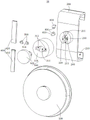
FIG. 2 is a schematic diagram of an explosion structure of the sound guide module according to an embodiment of the present invention;
FIG. 3 is a schematic structural diagram of a fixing member of a sound guide module according to an embodiment of the present invention;
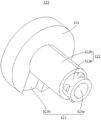
FIG. 4 is a schematic structural diagram of a second rotating member of the sound guide module according to an embodiment of the present invention;
FIG. 5 is a schematic partial structure diagram of a sound guide module according to an embodiment of the present invention;
FIG. 6 is another partial schematic structural diagram of a sound guide module according to an embodiment of the present invention;
fig. 7 is a partial structural view of an embodiment of a distance adjustment member of a sound guide module according to the present invention.
The reference numbers illustrate:
| reference numerals | Name (R) | Reference numerals | Name (R) |
| 10 | |
321 | |
| 20 | |
322 | Plug-in |
| 21 | |
322a | |
| 22 | |
322b | |
| 100 | |
323 | First sub |
| 200 | |
323a | First leading |
| 201 | Bayonet | 323b | Second leading |
| 202 | Second leading |
400 | Distance adjusting piece |
| 202a | Sound guiding |
401 | Second sub |
| 202b | Sound guide hole | 410 | A first regulating |
| 210 | |
411 | External tooth convex |
| 211 | Second mounting groove | 420 | A second regulating |
| 220 | |
421 | |
| 300 | |
500 | |
| 310 | First rotating |
510 | First |
| 311 | Hole of stepping down | 600 | Anticlockwise limiting |
| 312 | |
610 | Second |
| 320 | Second rotating member |
The implementation, functional features and advantages of the objects of the present invention will be further explained with reference to the accompanying drawings.
Detailed Description
The technical solutions in the embodiments of the present invention will be clearly and completely described below with reference to the drawings in the embodiments of the present invention, and it is obvious that the described embodiments are only a part of the embodiments of the present invention, and not all of the embodiments. All other embodiments, which can be obtained by a person skilled in the art without inventive step based on the embodiments of the present invention, are within the scope of protection of the present invention.
It should be noted that, if directional indications (such as up, down, left, right, front, and back … …) are involved in the embodiment of the present invention, the directional indications are only used to explain the relative positional relationship between the components, the movement situation, and the like in a specific posture (as shown in the drawing), and if the specific posture is changed, the directional indications are changed accordingly.
In addition, if there is a description of "first", "second", etc. in an embodiment of the present invention, the description of "first", "second", etc. is for descriptive purposes only and is not to be construed as indicating or implying relative importance or implicitly indicating the number of technical features indicated. Thus, a feature defined as "first" or "second" may explicitly or implicitly include at least one such feature. In addition, if appearing throughout the text, "and/or" is meant to include three juxtaposed aspects, taking "A and/or B" as an example, including either the A aspect, or the B aspect, or both A and B satisfied aspects. In addition, technical solutions between various embodiments may be combined with each other, but must be realized by a person skilled in the art, and when the technical solutions are contradictory or cannot be realized, such a combination should not be considered to exist, and is not within the protection scope of the present invention.
The invention provides a sound guide module.
In an embodiment of the present invention, as shown in fig. 1, the sound guiding module 10 is applied to a head-mounted display device, the head-mounted display device includes a host 20, the host 20 is provided with a sound outlet, the sound guiding module 10 includes an adjusting component and an ear muff 100, the adjusting component is movably connected to the host 20 and covers the sound outlet, the adjusting component is provided with a first sound guiding channel communicated with the sound outlet, and the ear muff 100 is movably connected to the host 20 through the adjusting component and communicated with the first sound guiding channel.
In the prior art, the sound emitted by the speaker of the head-mounted display device is emitted through the sound outlet hole of the host 20, so that on one hand, for the user, not only the immersion feeling of the user is reduced, but also the privacy feeling of the user is deteriorated; on the other hand, when the user uses the head mounted display device, the sound radiated outside may also cause interference to surrounding people.
In the invention, the sound outlet hole of the host 20 is communicated with the ear muff 100 through the first sound guide channel of the adjusting component, so that the sound of the speaker can be transmitted to the ear muff 100, after a user wears the head-mounted display device, the ear muff 100 covers the ear, and the sound of the head-mounted display device can be transmitted into the ear through the ear muff 100, thereby avoiding the interference to surrounding personnel caused by the external placement of the sound, and improving the immersion and privacy of the user. Moreover, the sound originally to be emitted from the sound outlet of the main unit 20 is collected to the ear muff 100 through the first sound guiding channel of the adjusting component, so that the volume heard by the user can be increased. In addition, the ear muffs 100 are movably connected to the host 20 through the adjusting assembly, so that the user can adjust the position of the ear muffs 100 relative to the ears through the adjusting assembly, so that the ear muffs 100 can cover the ears, thereby ensuring that the sound of the ear muffs 100 can be transmitted to the ears of the user. When different users wear the display device, the same sound guide module 10 can be used, the ear muffs 100 are adjusted to proper positions through the adjusting components, and then the sound of the head-mounted display device can be heard through the ear muffs 100, so that the universality of the sound guide module 10 is improved.
Further, in this embodiment, as shown in fig. 1 to fig. 3, the sound guiding module 10 further includes a fixing element 200, the fixing element 200 is fixedly connected to the host 20, the adjusting component is movably connected to the fixing element 200, the fixing element 200 is provided with a second sound guiding channel 202, and the first sound guiding channel is communicated with the sound outlet hole through the second sound guiding channel 202. That is, the adjusting member is indirectly connected to the main body 20 through the fixing member 200, and the first sound guiding channel is indirectly connected to the sound outlet through the second sound guiding channel 202. Thus, it is not necessary to add a structure for movably connecting the adjusting assembly to the main unit 20, and it can be understood that the fixing member 200 should have a portion for movably connecting the adjusting assembly and a portion for fixedly connecting to the main unit 20, and for the main units 20 with different structures, the structure of the fixing member 200 for fixedly connecting to the main unit 20 can be adaptively changed, so that the sound guide module 10 of the present invention can be adapted to the main units 20 with different structures. Of course, in other embodiments, the adjustment assembly may be directly connected to the host 20.
In addition, the first sound guiding channel and the second sound guiding channel 202 are constructed of a sound insulating material, or the surfaces of the first sound guiding channel and the second sound guiding channel 202 are coated with a sound insulating paint. Specifically, the material of the wall body of first leading sound passageway and second leading sound passageway 202 sets up to the material that gives sound insulation, or, the internal surface or the surface coating sound insulation coating of first leading sound passageway and second leading sound passageway 202, the homoenergetic reduces the effluvium of sound to the sound quality that the guarantee user listened through ear muff 100, thereby promote user's seeing and hearing and experiencing.
Further, the fixing member 200 is detachably connected to the main unit 20, so that the same sound guide module 10 can be mounted on different main units 20, thereby further improving the versatility of the sound guide module 10. The fixing member 200 can be fixedly connected to the host 20 by means of a snap fit or an insertion or a screw locking. Specifically, as shown in fig. 2 and 3, in the present embodiment, the fixing member 200 is provided with a bayonet 201, and is clamped outside the sound outlet hole through the bayonet 201. In this manner, the sound leading module 10 can be easily and quickly mounted to the main unit 20 or detached from the main unit 20. Moreover, the detachable connection mode does not need to change the structure of the host 20 and can not damage the structure of the host 20. Optionally, the host 20 includes a host body 21 and side arms 22 disposed on two opposite sides of the host body 21, when the head-mounted display device is worn, the side arms 22 on two sides are clamped on two sides of the head, so that the host body 21 is fixed, without loss of generality, the sound emitting hole is opened at one end of the side arms 22 far away from the host body 21, that is, one end of the fixing member 200, which is far away from the host body 21, where the side arm 22 is clamped by the clamp, so that the position of the earmuff 100 is close to the ear, and the user can perform small-range adjustment, so that the earmuff 100 can cover the ear. Of course, in other embodiments, the sound outlet hole may be disposed on the main body 21, and the fixing member 200 may extend to the ear direction by a sufficient length, so as to reduce the adjustment range of the adjustment assembly.
In one embodiment, as shown in fig. 2, the adjusting assembly comprises an angle adjuster 300 and a distance adjuster 400, wherein the angle adjuster 300 is used for adjusting the angle of the earmuff 100 relative to the fixing member 200, and the distance adjuster 400 is used for adjusting the distance of the earmuff 100 relative to the fixing member 200. The state that the user wears the display device is the direction reference, adjusts the relative mounting 200's of ear muff 100 through angle adjusting part 300, can make the relative ear back-and-forth movement of ear muff 100, adjusts the relative mounting 200's of ear muff 100 distance through distance adjusting part 400, can make ear muff 100 reciprocate relative to the ear to be convenient for the user and adjust ear muff 100 to the position that can cover the ear. Of course, in other embodiments, only one adjusting element may be provided to simultaneously satisfy the adjustment of the angle and the distance.
Further, in this embodiment, as shown in fig. 2, the angle adjusting element 300 includes a first rotating element 310 and a second rotating element 320 rotatably connected to the fixed element 200, the first rotating element 310 is configured to drive the ear cup 100 to rotate clockwise relative to the fixed element 200, and the second rotating element 320 is configured to drive the ear cup 100 to rotate counterclockwise relative to the fixed element 200. So, can be according to the front and back position of current ear muff 100 relative ear, pertinence ground carries out clockwise adjustment or anticlockwise regulation to ear muff 100, can avoid the amplitude of regulation too big to promote the operation convenience that the user carried out the regulation. Of course, in other embodiments, the same angle adjustment member 300 can be adjusted clockwise or counterclockwise, or the front and back positions of the ear cap 100 relative to the ear can be adjusted by a single first rotation member 310 or second rotation member 320.
Further, in the present embodiment, as shown in fig. 2, an installation convex portion 210 is convexly disposed on an outer side of the fixing member 200, an installation hole 220 is concavely disposed on the installation convex portion 210, one of the first rotating member 310 and the second rotating member 320 is rotatably sleeved outside the installation convex portion 210, and the other one is rotatably inserted into the installation hole 220. Thus, the first rotating member 310 and the second rotating member 320 can be movably connected to the fixed member 200, and the first rotating member 310 and the second rotating member 320 are driven to rotate relative to the fixed member 200, so as to drive the ear muff 100 to rotate relative to the fixed member 200. In addition, the space outside the fixing member 200 can be effectively utilized, the phenomenon that the volume of the sound guide module 10 is too large and too large weight burden is brought to a user is avoided, and the user experience feeling of using the sound guide module 10 is favorably guaranteed.
Specifically, as shown in fig. 2, the first rotating member 310 is provided with a relief hole 311, the mounting protrusion 210 is accommodated in the relief hole 311, the second rotating member 320 is provided with a main body 321 and an inserting protrusion 322 protruding from the main body 321, the inserting protrusion 322 is inserted into the mounting hole 220, and the main body 321 is located on a side of the first rotating member 310 away from the host 20. As shown in fig. 4, the insertion convex portion 322 includes a first insertion section 322a inserted into the installation hole 220 and a second insertion section 322b inserted into the relief hole 311, and particularly, to reduce the resistance of the first insertion section 322a inserted into the installation hole 220, the outer diameter of the first insertion section 322a is smaller than the inner diameter of the installation hole 220, and the first insertion section is tightly fitted with the installation hole 220 through a plurality of convex points protruding from the outer periphery. In this way, the outer periphery of the first rotating member 310 and the main body 321 of the second rotating member 320 can be exposed to the outside, so as to facilitate the operation of the user and ensure the user experience. Of course, in other embodiments, the second rotating element 320 may be provided with a driving protrusion protruding from the end of the inserting protrusion 322 far away from the fixing element 200 toward the direction far away from the fixing element 200, which is also convenient for the user to drive.
Further, in this embodiment, as shown in fig. 1, two ends of the distance adjusting member 400 are respectively and fixedly connected to the ear muff 100 and the second rotating member 320, and the length of the distance adjusting member 400 is adjustable, as shown in fig. 5 and 6, the adjusting assembly further includes a clockwise limiting member 500 and a counterclockwise limiting member 600, the clockwise limiting member 500 is disposed between the first rotating member 310 and the second rotating member 320 for limiting the second rotating member 320 from rotating clockwise relative to the first rotating member 310, and the counterclockwise limiting member 600 is disposed between the fixed member 200 and the first rotating member 310 for limiting the first rotating member 310 from rotating counterclockwise relative to the fixed member 200. In this embodiment, when the user needs to drive the ear muff 100 to rotate counterclockwise, the user can drive the second rotating member 320 to rotate counterclockwise by driving the second rotating member 320 to rotate counterclockwise, and the second rotating member 320 can drive the ear muff 100 to rotate counterclockwise by the distance adjusting member 400, when the ear muff 100 is adjusted in place, the user removes the acting force applied to the second rotating member 320, and the second rotating member 320 cannot be reset under the limitation of the clockwise limiting member 500, so that the ear muff 100 can be stably located at the adjusted position; when the user needs to drive the ear muff 100 to rotate clockwise, the first rotating member 310 and the second rotating member 320 can be driven to rotate clockwise simultaneously, i.e. the ear muff 100 can be driven to rotate clockwise by the distance adjusting member 400, when the ear muff 100 is adjusted in place, the external force of the first rotating member 310 and the second rotating member 320 is removed, and the ear muff 100 can not reset under the limitation of the counterclockwise limiting member 600 on the first rotating member 310. So, can adjust the angle of ear muff 100 relatively accurately to the operation experience that the user adjusted ear muff 100 has been promoted. Of course, in other embodiments, an end of the distance adjustment member 400 away from the ear muff 100 can move between the first rotating member 310 and the second rotating member 320, when the ear muff 100 needs to be driven to rotate clockwise, the end of the distance adjustment member 400 is driven to be separated from the second rotating member 320 and fixed with the first rotating member 310, and when the ear muff 100 needs to be driven to rotate counterclockwise, the same operation can be performed.
Further, in the present embodiment, as shown in fig. 6, the clockwise limiting element 500 is provided with a first matching arc surface 510, the first matching arc surface 510 extends towards the direction close to the second rotating element 320 in the counterclockwise direction to contact and match with the outer periphery of the insertion convex portion 322, and at a position where the second rotating element 320 contacts with the first matching arc surface 510, on a cross section perpendicular to the axial direction of the insertion convex portion 322, an included angle is formed between a tangent of the first matching arc surface 510 and a tangent of the outer contour of the mounting convex portion 210; as shown in fig. 5, the counterclockwise limiting member 600 is disposed on the mounting protrusion 210, the counterclockwise limiting member 600 is disposed with a second engaging arc 610, the second engaging arc 610 extends toward a direction close to the first rotating member 310 in a clockwise direction to contact and engage with the inner periphery of the first rotating member 310, and an included angle is formed between a tangent of the second engaging arc 610 and a tangent of the inner contour of the first rotating member 310 at a position where the first rotating member 310 contacts with the second engaging arc 610. Of course, in other embodiments, the clockwise limiting element 500 and the counterclockwise limiting element 600 can perform the limiting function in other manners, such as a manner of engaging tooth grooves; alternatively, the clockwise limiting element 500 may be engaged with other portions of the second rotating element 320, and the counterclockwise limiting element 600 may also be engaged with other portions of the first rotating element 310.
Specifically, the first rotating member 310 is provided with a first mounting groove 312 on each of two opposite sides of the insertion convex portion 322, a clockwise retaining member 500 is correspondingly mounted in the first mounting groove 312, the clockwise retaining member 500 is in contact fit with the outer periphery of the insertion convex portion 322 of the second rotating member 320 through a first mating arc surface 510, two opposite sides of the mounting convex portion 210 are respectively provided with a second mounting groove 211, a counterclockwise retaining member 600 is mounted in the second mounting groove 211, the counterclockwise retaining member 600 is in contact fit with the inner periphery of the first rotating member 310 through a second mating arc surface 610, so that the first rotating member 310 can be relatively fixed with the fixing member 200 under the limitation of the second mating arc surface 610 without external force, the second rotating member 320 can be relatively fixed with the fixing member 200 under the limitation of the first mating arc surface 510, and the earmuff 100 can be relatively fixed with the host 20, because the relative positions of the host 20 and the user's head are fixed, the earmuff 100 can also be fixed relative to the user's ear. Without loss of generality, the clockwise limiting member 500 and the counterclockwise limiting member 600 are respectively fixedly mounted in the first mounting groove 312 and the second mounting groove 211 by bolts.
Further, when the second rotating member 320 rotates counterclockwise relative to the first rotating member 310, the second rotating member 320 can drive the ear muff 100 to rotate counterclockwise without being limited by the first engaging arc 510, when the ear muff 100 is adjusted in place, the external force on the second rotating member 320 is removed, and under the limitation of the first engaging arc 510 and the second engaging arc 610, the ear muff 100 can be kept relatively fixed with the ear of the user, in particular, the first engaging arc 510 has a great limiting effect on the clockwise rotation of the second rotating member 320 relative to the first rotating member 310, and the ear muff 100 can be prevented from rotating clockwise in the reverse direction and being reset to the position before adjustment; when the first rotating member 310 and the second rotating member 320 synchronously rotate clockwise relative to the fixed member 200, the first rotating member 310 is not limited by the second engaging arc 610, and the second rotating member 320 is not limited by the first engaging arc 510, so that the earmuff 100 can be driven to rotate clockwise, when the earmuff 100 is adjusted in place, after the external force on the first rotating member 310 and the second rotating member 320 is removed, under the limitation of the first engaging arc 510 and the second engaging arc 610, the earmuff 100 can be kept relatively fixed with the ears of a user, in particular, the second engaging arc 610 has a great limiting effect on the counterclockwise rotation of the first rotating member 310 relative to the fixed member 200, and the position resetting before the adjustment due to the reverse counterclockwise rotation of the earmuff 100 can be avoided.
Further, in this embodiment, as shown in fig. 7, the distance adjusting member 400 includes a first adjusting portion 410 and a second adjusting portion 420, one end of the first adjusting portion 410 and one end of the second adjusting portion 420 are respectively fixedly connected to the ear cup 100 and the second rotating member 320, and the other end is movably connected to enable the distance between the ear cup 100 and the second rotating member 320 to be adjustable. Thus, by moving the connecting ends of the first adjusting part 410 and the second adjusting part 420 relatively, the distance between the ear muff 100 and the second rotating part 320 can be adjusted to adjust the distance between the ear muff 100 and the user's ear. Specifically, if the two connected ends move towards each other, the earmuff 100 will displace upwards relative to the main frame 20, and if the two connected ends move away from each other, the earmuff 100 will displace downwards relative to the main frame 20. The adjustment of the first rotating member 310 and the second rotating member 320 can ensure that the earplug can be adjusted to a proper position to ensure the audio-visual experience of the user. Of course, in other embodiments, the distance adjustment member 400 may be integrally formed and may be retractable, so as to adjust the distance between the ear cup 100 and the user's ear.
In an embodiment, one end of one of the first and second adjustment parts 410 and 420 is provided with an inner spline 421, and one end of the other is provided with an outer spline 411, and the outer spline 411 is inserted into and engaged with the inner spline 421, so that the first and second adjustment parts 410 and 420 are movably connected. Specifically, in this embodiment, the first adjusting part 410 is provided with the external protrusions 411, the second adjusting part 420 is provided with the internal splines 421, and the first adjusting part 410 is inserted into the second adjusting part 420, it can be understood that the effective length of the distance adjusting member 400 will be changed along with the different meshing lengths of the external protrusions 411 and the internal splines 421, so that the adjustment of the distance between the ear muffs 100 and the ears of the user can be realized. Of course, in other embodiments, one of the first adjustment portion 410 and the second adjustment portion 420 may be provided with an internal thread, and the other may be provided with an external thread, so that the effective length of the distance adjustment member 400 may be adjusted by thread matching, so as to adjust the distance between the ear mask 100 and the ear of the user.
Further, in the present embodiment, as shown in fig. 3, 4 and 7, the first sound guiding channel includes a first sub sound guiding channel 323 disposed on the second rotating member 320 and a second sub sound guiding channel 401 disposed on the distance adjusting member 400; both ends of the second sound guiding channel 202 are connected to the sound outlet hole and the mounting hole 220, one end of the first sub sound guiding channel 323 is connected to the inserting protrusion 322 to be connected to the mounting hole 220, one end of the second sub sound guiding channel 401 is connected to the other end of the first sub sound guiding channel 323, and the other end is connected to the ear muff 100. It can be understood that the second sound guiding channel 202 is not communicated with the external environment to ensure the sound of the sound outlet hole can be transmitted to the mounting hole 220, the first sub sound guiding channel 323 is formed on the second rotating member 320, one end of which is communicated with the second sound guiding channel 202, and the other end of which is communicated with the second sub sound guiding channel 401 disposed in the distance adjusting member 400 to be communicated with the ear cup 100. In this way, the sound emitted from the sound outlet hole of the speaker is transmitted to the ear muff 100 through the second sound guiding channel 202, the first sub sound guiding channel 323 and the second sub sound guiding channel 401 in sequence, and can be finally transmitted into the ear of the user. Without loss of generality, the second sound guiding channel 202 includes a sound guiding blind groove 202a and a sound guiding hole 202b which are communicated with each other, and is communicated with the sound outlet hole through the sound guiding blind groove 202a, and is communicated with the mounting hole 220 through the sound guiding hole 202b, the first sub sound guiding channel 323 includes a first sound guiding section 323a which is arranged through the insertion convex portion 322, and a second sound guiding section 323b which is arranged on the main body portion 321, the first adjusting portion 410 and the second adjusting portion 420 are both arranged in a hollow structure, so that a second sub sound guiding channel 401 is formed in the distance adjusting member 400, and the second adjusting portion 420 is inserted in the second sound guiding section 323b, so that the second sub sound guiding channel 401 is communicated with the first sub sound guiding channel 323.
The present invention further provides a head-mounted display device, which includes a sound guiding module 10 and a host 20 for installing the sound guiding module 10, and the specific structure of the sound guiding module 10 refers to the above embodiments, and since the head-mounted display device adopts all the technical solutions of all the above embodiments, the head-mounted display device at least has all the beneficial effects brought by the technical solutions of the above embodiments, and details are not repeated herein.
The above description is only an alternative embodiment of the present invention, and is not intended to limit the scope of the present invention, and all modifications and equivalents made by the contents of the present specification and the accompanying drawings, or directly/indirectly applied to other related technical fields, which are within the spirit of the present invention, are included in the scope of the present invention.
Claims (13)
Priority Applications (1)
| Application Number | Priority Date | Filing Date | Title |
|---|---|---|---|
| CN202210284533.1A CN114666690B (en) | 2022-03-22 | 2022-03-22 | Sound guide module and head-mounted display device |
Applications Claiming Priority (1)
| Application Number | Priority Date | Filing Date | Title |
|---|---|---|---|
| CN202210284533.1A CN114666690B (en) | 2022-03-22 | 2022-03-22 | Sound guide module and head-mounted display device |
Publications (2)
| Publication Number | Publication Date |
|---|---|
| CN114666690A true CN114666690A (en) | 2022-06-24 |
| CN114666690B CN114666690B (en) | 2026-03-03 |
Family
ID=82031753
Family Applications (1)
| Application Number | Title | Priority Date | Filing Date |
|---|---|---|---|
| CN202210284533.1A Active CN114666690B (en) | 2022-03-22 | 2022-03-22 | Sound guide module and head-mounted display device |
Country Status (1)
| Country | Link |
|---|---|
| CN (1) | CN114666690B (en) |
Cited By (3)
| Publication number | Priority date | Publication date | Assignee | Title |
|---|---|---|---|---|
| CN115767352A (en) * | 2022-11-18 | 2023-03-07 | 维沃移动通信有限公司 | Wearable device |
| CN115933199A (en) * | 2022-12-27 | 2023-04-07 | 维沃移动通信有限公司 | Wearable device |
| CN117784418A (en) * | 2022-09-22 | 2024-03-29 | 北京字跳网络技术有限公司 | Sound guide device and head-mounted display equipment |
Citations (13)
| Publication number | Priority date | Publication date | Assignee | Title |
|---|---|---|---|---|
| KR20050112326A (en) * | 2004-05-25 | 2005-11-30 | 엠엠기어 주식회사 | Ear-headphone |
| US20080170738A1 (en) * | 2007-01-16 | 2008-07-17 | Sony Ericsson Mobile Communications Ab | Adjustable earphones for portable devices |
| CN105376669A (en) * | 2015-12-10 | 2016-03-02 | 英国奥科斯国际有限公司 | In-ear angle adaptive earphone |
| CN206193360U (en) * | 2016-11-17 | 2017-05-24 | 厦门轻居科技有限公司 | Wear -type VR equipment |
| CN206506662U (en) * | 2017-01-24 | 2017-09-19 | 深圳市冠旭电子股份有限公司 | headphones |
| CN107318063A (en) * | 2017-08-30 | 2017-11-03 | 歌尔科技有限公司 | A kind of helmet with earphone |
| CN108710213A (en) * | 2018-08-24 | 2018-10-26 | 歌尔科技有限公司 | A kind of helmet |
| CN208609160U (en) * | 2018-07-30 | 2019-03-15 | 青岛小鸟看看科技有限公司 | A kind of loudspeaker auricular concha and a kind of helmet for helmet |
| CN210091102U (en) * | 2019-07-29 | 2020-02-18 | 中建欣立建设发展集团股份有限公司 | Immersive display device for virtual reality building system |
| CN212905728U (en) * | 2020-09-24 | 2021-04-06 | 昆山联滔电子有限公司 | Head-mounted display device |
| CN212970056U (en) * | 2020-09-28 | 2021-04-13 | 深圳市森集科技有限公司 | Directive property transaudient near field earphone |
| KR102252442B1 (en) * | 2020-01-13 | 2021-05-14 | (주)마키나 | Small size sound device with multi-adjustment ear hanger |
| CN215871774U (en) * | 2021-05-17 | 2022-02-18 | 歌尔股份有限公司 | Earphone and electronic product |
-
2022
- 2022-03-22 CN CN202210284533.1A patent/CN114666690B/en active Active
Patent Citations (13)
| Publication number | Priority date | Publication date | Assignee | Title |
|---|---|---|---|---|
| KR20050112326A (en) * | 2004-05-25 | 2005-11-30 | 엠엠기어 주식회사 | Ear-headphone |
| US20080170738A1 (en) * | 2007-01-16 | 2008-07-17 | Sony Ericsson Mobile Communications Ab | Adjustable earphones for portable devices |
| CN105376669A (en) * | 2015-12-10 | 2016-03-02 | 英国奥科斯国际有限公司 | In-ear angle adaptive earphone |
| CN206193360U (en) * | 2016-11-17 | 2017-05-24 | 厦门轻居科技有限公司 | Wear -type VR equipment |
| CN206506662U (en) * | 2017-01-24 | 2017-09-19 | 深圳市冠旭电子股份有限公司 | headphones |
| CN107318063A (en) * | 2017-08-30 | 2017-11-03 | 歌尔科技有限公司 | A kind of helmet with earphone |
| CN208609160U (en) * | 2018-07-30 | 2019-03-15 | 青岛小鸟看看科技有限公司 | A kind of loudspeaker auricular concha and a kind of helmet for helmet |
| CN108710213A (en) * | 2018-08-24 | 2018-10-26 | 歌尔科技有限公司 | A kind of helmet |
| CN210091102U (en) * | 2019-07-29 | 2020-02-18 | 中建欣立建设发展集团股份有限公司 | Immersive display device for virtual reality building system |
| KR102252442B1 (en) * | 2020-01-13 | 2021-05-14 | (주)마키나 | Small size sound device with multi-adjustment ear hanger |
| CN212905728U (en) * | 2020-09-24 | 2021-04-06 | 昆山联滔电子有限公司 | Head-mounted display device |
| CN212970056U (en) * | 2020-09-28 | 2021-04-13 | 深圳市森集科技有限公司 | Directive property transaudient near field earphone |
| CN215871774U (en) * | 2021-05-17 | 2022-02-18 | 歌尔股份有限公司 | Earphone and electronic product |
Non-Patent Citations (1)
| Title |
|---|
| 卢龙;何梦圆;袁诗洋;王亚飞;: "一种导音耳机", 数码世界, no. 02, 1 February 2018 (2018-02-01) * |
Cited By (3)
| Publication number | Priority date | Publication date | Assignee | Title |
|---|---|---|---|---|
| CN117784418A (en) * | 2022-09-22 | 2024-03-29 | 北京字跳网络技术有限公司 | Sound guide device and head-mounted display equipment |
| CN115767352A (en) * | 2022-11-18 | 2023-03-07 | 维沃移动通信有限公司 | Wearable device |
| CN115933199A (en) * | 2022-12-27 | 2023-04-07 | 维沃移动通信有限公司 | Wearable device |
Also Published As
| Publication number | Publication date |
|---|---|
| CN114666690B (en) | 2026-03-03 |
Similar Documents
| Publication | Publication Date | Title |
|---|---|---|
| CN114666690B (en) | Sound guide module and head-mounted display device | |
| EP3796668B1 (en) | Earpiece | |
| CN113568169A (en) | virtual reality head mounted display | |
| JP4740317B2 (en) | Attachment structure of bone conduction device to glasses | |
| JP2009171303A (en) | headphone | |
| EP3637794B1 (en) | Head wearable equipment with adjustable bone-conductive acoustic device | |
| CN207181820U (en) | Virtual reality head-mounted display apparatus | |
| CN114938483B (en) | Ergonomic headphone | |
| CN108776393A (en) | a kind of glasses | |
| US20110143820A1 (en) | Headphones with attached microphone boom | |
| CN214481174U (en) | Headset and head-mounted Bluetooth headset | |
| CN210579163U (en) | Head-wearing earphone | |
| CN213403452U (en) | Earphone and electronic product | |
| KR101562129B1 (en) | hearing protection apparatus of earphone | |
| CN209517453U (en) | adjustable earphones | |
| CN223182259U (en) | Headset earphone | |
| CN205902026U (en) | Separation blade lever earphone fine setting structure and earphone | |
| CN220475916U (en) | Earphone and Bluetooth earphone suit | |
| CN111083594B (en) | Headset | |
| CN223334768U (en) | Headphone stand assembly and headphone | |
| CN206759679U (en) | In-Ear Headphones | |
| CN212229329U (en) | VR head-mounted display equipment | |
| CN217957271U (en) | Flying wing rotating structure of headset and headset | |
| CN205902022U (en) | Knob earphone fine-tuning structure and earphone | |
| CN220553627U (en) | Interface assembly and electronic equipment |
Legal Events
| Date | Code | Title | Description |
|---|---|---|---|
| PB01 | Publication | ||
| PB01 | Publication | ||
| SE01 | Entry into force of request for substantive examination | ||
| SE01 | Entry into force of request for substantive examination | ||
| GR01 | Patent grant | ||
| GR01 | Patent grant |