CN114658938A - Area protection latus rectum can take area to press plug fluid coupling - Google Patents
Area protection latus rectum can take area to press plug fluid coupling Download PDFInfo
- Publication number
- CN114658938A CN114658938A CN202210367118.2A CN202210367118A CN114658938A CN 114658938 A CN114658938 A CN 114658938A CN 202210367118 A CN202210367118 A CN 202210367118A CN 114658938 A CN114658938 A CN 114658938A
- Authority
- CN
- China
- Prior art keywords
- sealing
- socket
- plug
- valve core
- sealing ring
- Prior art date
- Legal status (The legal status is an assumption and is not a legal conclusion. Google has not performed a legal analysis and makes no representation as to the accuracy of the status listed.)
- Pending
Links
- 239000012530 fluid Substances 0.000 title claims abstract description 49
- 230000008878 coupling Effects 0.000 title 1
- 238000010168 coupling process Methods 0.000 title 1
- 238000005859 coupling reaction Methods 0.000 title 1
- 210000000664 rectum Anatomy 0.000 title 1
- 238000007789 sealing Methods 0.000 claims abstract description 242
- 230000013011 mating Effects 0.000 claims abstract description 16
- 230000001681 protective effect Effects 0.000 claims abstract description 14
- 238000009434 installation Methods 0.000 claims description 20
- 238000003780 insertion Methods 0.000 claims description 11
- 230000037431 insertion Effects 0.000 claims description 11
- 230000009471 action Effects 0.000 claims description 5
- 238000002955 isolation Methods 0.000 claims 1
- 238000000034 method Methods 0.000 description 12
- 230000008569 process Effects 0.000 description 10
- 238000010586 diagram Methods 0.000 description 8
- 230000000694 effects Effects 0.000 description 5
- 239000007788 liquid Substances 0.000 description 5
- 238000001816 cooling Methods 0.000 description 4
- 239000012809 cooling fluid Substances 0.000 description 4
- 238000006073 displacement reaction Methods 0.000 description 4
- 238000005516 engineering process Methods 0.000 description 3
- 230000004907 flux Effects 0.000 description 3
- 230000017525 heat dissipation Effects 0.000 description 3
- 238000004891 communication Methods 0.000 description 2
- 238000011161 development Methods 0.000 description 2
- 239000012535 impurity Substances 0.000 description 2
- 238000012986 modification Methods 0.000 description 2
- 230000004048 modification Effects 0.000 description 2
- XLYOFNOQVPJJNP-UHFFFAOYSA-N water Substances O XLYOFNOQVPJJNP-UHFFFAOYSA-N 0.000 description 2
- 230000009286 beneficial effect Effects 0.000 description 1
- 230000008901 benefit Effects 0.000 description 1
- 230000005540 biological transmission Effects 0.000 description 1
- 230000006835 compression Effects 0.000 description 1
- 238000007906 compression Methods 0.000 description 1
- 238000007667 floating Methods 0.000 description 1
- 230000010354 integration Effects 0.000 description 1
- 239000000463 material Substances 0.000 description 1
- 238000000926 separation method Methods 0.000 description 1
Images





Classifications
-
- F—MECHANICAL ENGINEERING; LIGHTING; HEATING; WEAPONS; BLASTING
- F16—ENGINEERING ELEMENTS AND UNITS; GENERAL MEASURES FOR PRODUCING AND MAINTAINING EFFECTIVE FUNCTIONING OF MACHINES OR INSTALLATIONS; THERMAL INSULATION IN GENERAL
- F16L—PIPES; JOINTS OR FITTINGS FOR PIPES; SUPPORTS FOR PIPES, CABLES OR PROTECTIVE TUBING; MEANS FOR THERMAL INSULATION IN GENERAL
- F16L29/00—Joints with fluid cut-off means
- F16L29/02—Joints with fluid cut-off means with a cut-off device in one of the two pipe ends, the cut-off device being automatically opened when the coupling is applied
Landscapes
- Engineering & Computer Science (AREA)
- General Engineering & Computer Science (AREA)
- Mechanical Engineering (AREA)
- Quick-Acting Or Multi-Walled Pipe Joints (AREA)
Abstract
本发明公开了一种带保护通径可带压插拔流体连接器,包括插头、与插头适配连接的插座;其中,所述插头包括安装外壳以及与安装外壳连接的对插外壳,所述对插外壳内设有径向滑动的插头密封元件,所述插座包括安装外壳、与安装外壳连接的导向外壳,所述导向外壳内设有插座密封组件,所述插座密封组件端部设有在导向外壳径向滑动的活动阀芯密封组件,活动阀芯密封组件外壁与导向外壳通过第三密封圈对实现径向密封;所述活动阀芯密封组件包括密封圈保护元件和插座活动阀芯,所述密封圈保护元件沿着插座活动阀芯内壁在插座密封组件的固定阀芯上实现径向滑动,且密封圈保护元件和插座活动阀芯通过第五密封圈实现径向密封。

The invention discloses a pressurized pluggable fluid connector with a protective diameter, comprising a plug and a socket adapted to connect with the plug; wherein, the plug comprises a mounting shell and a mating shell connected with the mounting shell, the A radially sliding plug sealing element is arranged in the mating housing, the socket includes a mounting housing and a guide housing connected with the mounting housing, the guide housing is provided with a socket sealing component, and the end of the socket sealing component is provided at the end of the socket sealing component. A movable valve core sealing assembly that slides radially on the guide shell, the outer wall of the movable valve core sealing assembly and the guide shell are radially sealed by a third sealing ring pair; the movable valve core sealing assembly includes a sealing ring protection element and a socket movable valve core, The sealing ring protection element realizes radial sliding on the fixed valve core of the socket sealing assembly along the inner wall of the socket movable valve core, and the sealing ring protection element and the socket movable valve core realize radial sealing through the fifth sealing ring.
Description
技术领域technical field
本发明涉及一种带保护通径可带压插拔流体连接器,属于流体连接器技术领域。The invention relates to a fluid connector with a protective diameter and can be plugged and unplugged under pressure, which belongs to the technical field of fluid connectors.
背景技术Background technique
随着设备中电子元器件不断向高频、高密度、高集成化方向发展,设备如何实现高效散热的问题越来越突出,液冷散热技术已成为解决此问题的首选方案。液冷散热技术现已广泛应用于航空、航天、电子、舰船、通讯、风电、电动汽车、数据中心等多个领域。With the continuous development of electronic components in equipment towards high frequency, high density and high integration, the problem of how to achieve efficient heat dissipation in equipment has become more and more prominent. Liquid cooling technology has become the preferred solution to this problem. Liquid cooling technology has been widely used in aviation, aerospace, electronics, ships, communications, wind power, electric vehicles, data centers and other fields.
随着技术的日益发展,电子设备趋向于高可靠性,急需高可靠型流体连接器实现被冷却模块和机箱之间流体的传输,但是此类现有连接器在操作过程中存在以下问题:With the increasing development of technology, electronic equipment tends to be highly reliable, and a highly reliable fluid connector is urgently needed to realize the transmission of fluid between the cooled module and the chassis. However, such existing connectors have the following problems during operation:
1、流体连接器流阻比较大,散热效果不理想。尤其是在轴向浮动比较大的范围内更不容易满足低流阻;1. The flow resistance of the fluid connector is relatively large, and the heat dissipation effect is not ideal. Especially in the range of relatively large axial floating, it is more difficult to meet the low flow resistance;
2、流体连接器在流道打开或者流道开合的过程,O形圈受水流压力影响,容易被冲掉、变形,多余物黏附,导致密封失效;2. During the process of opening or closing the flow channel of the fluid connector, the O-ring is affected by the pressure of the water flow, and is easily washed off, deformed, and the excess material adheres, resulting in seal failure;
3、现有大通径流体连接器,在插头、插座插接时轴向移动并与安装外壳内壁形成供液体通过的流道;流道打开瞬间,插头/插座流体通道中心的O形圈,在高速液体冲击而变形、脱落、杂质黏附导致泄露、产品失效或者插拔寿命不满足要求;3. The existing large-diameter fluid connectors move axially when the plug and socket are inserted and form a flow channel for the liquid to pass through with the inner wall of the installation shell; when the flow channel is opened, the O-ring in the center of the fluid channel of the plug/socket, in the High-speed liquid impact and deformation, falling off, impurity adhesion lead to leakage, product failure or plug life does not meet the requirements;
4、现有大通径流体连接器,插头与插座带压、大流量插拔时,存在密封圈损坏,插拔寿命低,泄露量大等问题,以及插合后压降较大影响整机散热等问题。4. In the existing large-diameter fluid connectors, when the plug and socket are under pressure and large flow, there are problems such as damage to the sealing ring, low plugging life, large leakage, etc., and the large pressure drop after insertion affects the heat dissipation of the whole machine And other issues.
发明内容SUMMARY OF THE INVENTION
本发明的目的在于提供一种带保护通径可带压插拔流体连接器,以解决现有技术插头与插座带压、大流量插拔时,存在密封圈损坏,插拔寿命低,泄露量大的缺陷。The purpose of the present invention is to provide a fluid connector with a protective diameter that can be plugged and unplugged under pressure, so as to solve the problem of damage to the sealing ring, low plugging life, and leakage when plugs and sockets are plugged and unplugged with pressure and large flow in the prior art. big flaw.
一种带保护通径可带压插拔流体连接器,包括插头、与插头适配连接的插座;A pluggable fluid connector with a protective passage under pressure, comprising a plug and a socket adapted to connect with the plug;
其中,所述插头包括安装外壳以及与安装外壳连接的对插外壳,且二者通过第一密封圈实现径向密封;所述对插外壳内设有径向滑动的插头密封元件,且二者通过第二密封圈实现径向密封;Wherein, the plug includes a mounting shell and a mating shell connected with the mounting shell, and the two are radially sealed by a first sealing ring; the mating shell is provided with a radially sliding plug sealing element, and the two are radially sealed. Radial sealing is achieved through the second sealing ring;
所述插座包括安装外壳、与安装外壳连接的导向外壳,二者通过第四密封圈实现径向密封;所述导向外壳内设有插座密封组件,所述插座密封组件端部设有在导向外壳径向滑动的活动阀芯密封组件,活动阀芯密封组件外壁与导向外壳通过第三密封圈对实现径向密封;The socket includes an installation casing and a guide casing connected with the installation casing, and the two are radially sealed by a fourth sealing ring; a socket sealing assembly is arranged in the guiding casing, and the end of the socket sealing assembly is provided on the guiding casing. The radially sliding movable valve core sealing assembly, the outer wall of the movable valve core sealing assembly and the guide casing are radially sealed through the third sealing ring pair;
所述活动阀芯密封组件包括密封圈保护元件和插座活动阀芯 ,所述密封圈保护元件沿着插座活动阀芯内壁在插座密封组件的固定阀芯上实现径向滑动,且密封圈保护元件和插座活动阀芯通过第五密封圈实现径向密封;The movable valve core sealing assembly includes a sealing ring protection element and a socket movable valve core, the sealing ring protection element realizes radial sliding on the fixed valve core of the socket sealing assembly along the inner wall of the socket movable valve core, and the sealing ring protects the element And the movable valve core of the socket realizes radial sealing through the fifth sealing ring;
当插头、插座插合开始至插合到底时,密封圈保护元件外壁一直将第二密封圈、第五密封圈与流体隔离。When the plug and socket start to be inserted to the end, the outer wall of the sealing ring protection element keeps the second sealing ring and the fifth sealing ring isolated from the fluid.
进一步地,所述插头还包括第一弹簧,所述第一弹簧设于安装外壳的内部,所述安装外壳内设有与第一弹簧一端连接的第一弹簧定位部,所述插头密封元件 包括第一弹簧限位部和密封元件密封段;所述第一弹簧限位部与第一弹簧另一端抵接,所述对插外壳设有与密封元件密封段匹配的第一限位部,还设有与安装外壳连接限位的插合限位部,插头、插座未插合时,在第一弹簧的顶推作用下插头密封元件与第一限位部抵接,插头密封元件与第二密封圈密封配合实现对插头前端的密封。Further, the plug further includes a first spring, the first spring is arranged inside the installation housing, the installation housing is provided with a first spring positioning portion connected with one end of the first spring, and the plug sealing element includes a first spring limiting part and a sealing element sealing segment; the first spring limiting part abuts against the other end of the first spring, the pair of plug-in housings is provided with a first limiting part matching the sealing element sealing segment, and also There is an insertion limit part connected to the installation shell, when the plug and the socket are not inserted, the plug sealing element is in contact with the first limit part under the pushing action of the first spring, and the plug sealing element is in contact with the second limit part. The sealing ring of the sealing ring realizes the sealing of the front end of the plug.
进一步地,所述活动阀芯密封组件与插座密封组件通过第二弹簧实现径向滑动,所述固定阀芯通过插座密封组件固定元件与安装外壳连接,所述固定阀芯与插座密封组件固定元件之间设有插座密封组件限位元件,所述第二弹簧一端套接在插座密封组件固定元件上,另一端与插座活动阀芯抵接。Further, the movable valve core sealing assembly and the socket sealing assembly realize radial sliding through the second spring, the fixed valve core is connected with the installation shell through the socket sealing assembly fixing element, and the fixed valve core and the socket sealing assembly fixing element A limiting element of the socket sealing assembly is arranged therebetween, one end of the second spring is sleeved on the fixing element of the socket sealing assembly, and the other end is in contact with the movable valve core of the socket.
进一步地,所述固定阀芯的靠近插头的一端设有固定阀芯密封段、内腔设有导流结构一、侧壁沿径向设置多个通流孔,远离插头的一端侧壁沿径向设置多个泄压孔。Further, the end of the fixed valve core close to the plug is provided with a fixed valve core sealing section, and the inner cavity is provided with a flow guide structure. First, the side wall is provided with a plurality of through holes along the radial direction, and the side wall of the end away from the plug is radially arranged. Set up multiple pressure relief holes.
进一步地,所述密封圈保护元件一端设有与固定阀芯密封段相抵的第三限位部,另一端设有第三弹簧固定件,两者中间通过第三弹簧实现径向移动。Further, one end of the sealing ring protection element is provided with a third limiting portion which is in contact with the sealing section of the fixed valve core, and the other end is provided with a third spring fixing member, and a third spring is used in the middle to realize radial movement.
进一步地,所述导向外壳靠近插头的一端设有用于限制活动阀芯密封组件轴向移动的第二限位部,插头、插座未插合时,在第三弹簧的顶推作用下使所述密封圈保护元件与固定阀芯 尾端部抵紧。Further, the end of the guide shell close to the plug is provided with a second limit portion for restricting the axial movement of the movable valve core sealing assembly. When the plug and the socket are not inserted, the third spring pushes the The sealing ring protection element is tightly abutted against the rear end of the fixed valve core.
进一步地,所述对插外壳、第一密封圈和安装外壳通过螺纹但不限于的方式联接。Further, the mating housing, the first sealing ring and the mounting housing are connected by means of threads but not limited to.
进一步地,所述固定阀芯为后端敞开、前端封闭的圆柱形中空结构。Further, the fixed valve core is a cylindrical hollow structure with an open rear end and a closed front end.
进一步地,所述插头和插座的一端为接插端,另一端为安装端。Further, one end of the plug and the socket is a plug end, and the other end is an installation end.
进一步地,所述插头密封元件靠近插座的一端设有导流结构二和通流孔。Further, the end of the plug sealing element close to the socket is provided with a second flow guide structure and a flow hole.
与现有技术相比,本发明所达到的有益效果:本发明在工作过程中插头、插座阀芯密封圈均未暴露在流速较大的流体中,阀芯密封圈一直处于被保护状态降低了密封圈的损耗并避免了密封圈被流体冲掉,提升了密封圈的使用寿命的同时还提高了连接器的带压拔插次数;此外,本发明采用特殊结构的密封组件组合实现对插座阀芯密封圈的保护,不仅限制密封组件径向位移并避免在流体冲击下造成的密封组件径向偏移甚至脱离弹簧,而且保护元件始终和阀芯一起往复运动,提高了密封组件在带压工作时及频繁插拔情况下的稳定性,还配合形成了尺寸大且与流体流通方向平滑过度的流孔,降低了流体在连接器内的流通阻力,同时独特的锥形导流结构可以有效减少涡流干扰,在相同冷却流体源供压情况下提高待冷却模块内的流体通量,从而实现更佳的冷却效果。Compared with the prior art, the beneficial effects achieved by the present invention are as follows: during the working process of the present invention, the plug and socket valve core sealing rings are not exposed to the fluid with a large flow rate, and the valve core sealing ring is always in a protected state. The loss of the sealing ring can prevent the sealing ring from being washed away by the fluid, and the service life of the sealing ring is improved, and the number of times of plugging and unplugging under pressure of the connector is also increased; The protection of the core sealing ring not only limits the radial displacement of the sealing assembly and avoids the radial displacement of the sealing assembly caused by the fluid impact or even the separation of the spring, but also the protection element always reciprocates with the valve core, which improves the performance of the sealing assembly under pressure. Stability under the condition of time and frequent plugging and unplugging, it also cooperates to form a large size and smooth flow hole with the fluid flow direction, which reduces the flow resistance of the fluid in the connector. At the same time, the unique conical diversion structure can effectively reduce the Eddy current interference increases the fluid flux in the module to be cooled under the same supply pressure of the cooling fluid source, thereby achieving better cooling effect.
附图说明Description of drawings
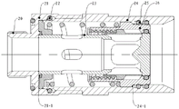
图1是本发明中插头的剖视结构示意图;Fig. 1 is the sectional structure schematic diagram of the plug in the present invention;
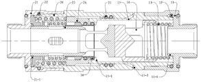
图2是本发明中插座的剖视结构示意图;Fig. 2 is the sectional structure schematic diagram of the socket in the present invention;
图3是本发明中插头的密封组件剖视结构示意图;FIG. 3 is a cross-sectional structural schematic diagram of the sealing assembly of the plug in the present invention;
图4是本发明中插座的密封组件剖视结构示意图;4 is a schematic cross-sectional view of the sealing assembly of the socket in the present invention;
图5是本发明中插座的另一密封组件剖视结构示意图;5 is a schematic cross-sectional structural diagram of another sealing assembly of the socket in the present invention;
图6是本发明中插头和插座插合贴合之初的状态示意图;6 is a schematic diagram of the state of the plug and the socket at the beginning of the plug and fit in the present invention;
图7是本发明中插头和插座插合到位后的状态示意图;Fig. 7 is the state schematic diagram after the plug and the socket are inserted in place in the present invention;
图8是本发明中插头和插座插合过程临界位置的状态示意图;Fig. 8 is the state schematic diagram of the critical position of the plug and socket insertion process in the present invention;
图9是本发明中插头和插座插合过程插合位置的状态示意图;Fig. 9 is the state schematic diagram of the insertion position during the insertion process of the plug and the socket in the present invention;
图中:1、插头;11、安装外壳;11-1、第一弹簧定位部;12、第一密封圈;13、第一弹簧;14、插头密封元件;14-2、密封元件密封段;14-3、导流结构二;14-4、通流孔;14-1、第一弹簧限位部; 15、对插外壳;15-1、第一限位部;15-2、插合限位部;16、第二密封圈; 2、插座;21、安装外壳;21-1、防脱结构;22、第四密封圈;23、插座密封组件;23-1、插座密封组件固定元件;23-2、固定阀芯; 23-2-1、泄压孔 ;23-2-2、通流孔 ;23-2-3、导流结构一;23-2-4、固定阀芯密封段;23-3、第二弹簧;23-4插座密封组件限位元件;24、导向外壳;24-1、第二限位部;25、第三密封圈对;26、活动阀芯密封组件;26-1、第三弹簧固定件;26-2、第三弹簧;26-3、密封圈保护元件;26-4、插座活动阀芯;26-5、第五密封圈;26-4-1第三限位部。In the figure: 1, the plug; 11, the installation shell; 11-1, the first spring positioning part; 12, the first sealing ring; 13, the first spring; 14, the plug sealing element; 14-2, the sealing element sealing section; 14-3, guide structure 2; 14-4, through-flow hole; 14-1, the first spring limit part; 15, the plug-in housing; 15-1, the first limit part; 15-2, the insertion Limiting part; 16. Second sealing ring; 2. Socket; 21. Mounting shell; 21-1. Anti-dropping structure; 22. Fourth sealing ring; 23. Socket sealing assembly; ;23-2, fixed valve core; 23-2-1, pressure relief hole; 23-2-2, flow hole; 23-2-3, diversion structure one; 23-2-4, fixed valve core seal Section; 23-3, the second spring; 23-4, the limit element of the socket sealing assembly; 24, the guide shell; 24-1, the second limit part; 25, the third sealing ring pair; 26, the movable valve core sealing assembly ;26-1, the third spring fixing part; 26-2, the third spring; 26-3, the sealing ring protection element; 26-4, the socket movable valve core; 26-5, the fifth sealing ring; 26-4- 1 The third limit part.
具体实施方式Detailed ways
为使本发明实现的技术手段、创作特征、达成目的与功效易于明白了解,下面结合具体实施方式,进一步阐述本发明。In order to make the technical means, creative features, achievement goals and effects realized by the present invention easy to understand, the present invention will be further described below with reference to the specific embodiments.
在本发明的描述中,需要理解的是,术语“中心”、“纵向”、“横向”、“上”、“下”、“前”、“后”、“左”、“右”、“竖直”、“水平”、“顶”、 “底”、“内”、“外”等指示的方位或位置关系为基于附图所示的方位或位置关系,仅是为了便于描述本发明和简化描述,而不是指示或暗示所指的装置或元件必须具有特定的方位、以特定的方位构造和操作,因此不能理解为对本发明的限制。此外,术语“第一”、“第二”等仅用于描述目的,而不能理解为指示或暗示相对重要性或者隐含指明所指示的技术特征的数量。由此,限定有“第一”、“第二”等的特征可以明示或者隐含地包括一个或者更多个该特征。在本发明的描述中,除非另有说明,“多个”的含义是两个或两个以上。In the description of the present invention, it should be understood that the terms "center", "portrait", "horizontal", "top", "bottom", "front", "rear", "left", "right", " The orientation or positional relationship indicated by vertical, horizontal, top, bottom, inner, outer, etc. is based on the orientation or positional relationship shown in the drawings, and is only for the convenience of describing the present invention and The description is simplified rather than indicating or implying that the device or element referred to must have a particular orientation, be constructed and operate in a particular orientation, and therefore should not be construed as limiting the invention. In addition, the terms "first", "second", etc. are used for descriptive purposes only, and should not be construed as indicating or implying relative importance or implying the number of indicated technical features. Thus, a feature defined as "first", "second", etc., may expressly or implicitly include one or more of that feature. In the description of the present invention, unless otherwise specified, "plurality" means two or more.
在本发明的描述中,需要说明的是,除非另有明确的规定和限定,术语“安装”、“相连”、“连接”应做广义理解,例如,可以是固定连接,也可以是可拆卸连接,或一体地连接;可以是机械连接,也可以是电连接;可以是直接相连,也可以通过中间媒介间接相连,可以是两个元件内部的连通。对于本领域的普通技术人员而言,可以通过具体情况理解上述术语在本发明中的具体含义。In the description of the present invention, it should be noted that the terms "installed", "connected" and "connected" should be understood in a broad sense, unless otherwise expressly specified and limited, for example, it may be a fixed connection or a detachable connection Connection, or integral connection; can be mechanical connection, can also be electrical connection; can be directly connected, can also be indirectly connected through an intermediate medium, can be internal communication between two elements. For those of ordinary skill in the art, the specific meanings of the above terms in the present invention can be understood through specific situations.
实施例1Example 1
请参阅图1至图4,本实施例介绍一种带保护通径带压插拔流体连接器,包括插头1和与该插头1适配的插座2,插头1和插座2的前端均为接插端,插头1包括安装外壳11、第一密封圈12、第一弹簧13、插头密封元件14、对插外壳15以及第二密封圈16,插头密封元件14滑动装配在对插外壳15内部前端,密封元件14包括第一弹簧限位部14-1、密封元件密封段14-2、锥形导流结构14-3,通流孔14-4;滑动密封元件14侧壁上设有通流孔14-3、锥形导流结构14-3和第一弹簧限位部14-1,第一弹簧限位部14-1可以是整圈或非整圈结构。Please refer to FIG. 1 to FIG. 4 . This embodiment introduces a plug-in fluid connector with a protective diameter under pressure, which includes a plug 1 and a socket 2 adapted to the plug 1. The front ends of the plug 1 and the socket 2 are connected to each other. The plug end, the plug 1 includes a mounting
所述安装外壳11与对插外壳15通过螺纹或者过盈连接,二者通过第一密封圈12实现径向密封。所述对插外壳15前端内壁凸设有用于限制插头密封元件14轴向移动的第一限位部15-1,以防止密封组件14继续向前端移动。插头1、插座2未插合时,在第一弹簧13的顶推作用下密封元件密封段14-2与第一限位部15-1抵接,此时密封组件14与第二密封圈14-1密封配合从而实现对插头1前端的密封。The mounting
在本实施例中,安外壳11用于径向限位第一弹簧13,对插外壳15的第一限位部15-1与插头密封元件14的密封段14-2前端相抵,第二密封圈16与对插外壳15实现密封配合,第一弹簧13弹簧端面分别与安外壳11内部端面、插头密封元件14的第一弹簧限位部的端面相抵,保证了弹簧的安装稳定性以及频繁插拔下的轴向压缩稳定性;In this embodiment, the mounting
插头密封元件14的前端为呈圆柱状的密封部,和第二密封圈16抵压配合实现对插头1内流体通道的密封;插头密封元件14的密封段14-2的前端内部设有导流结构二14-3,中端设有通流孔14-4、尾端内部设有整圈或非整圈的第一弹簧限位部14-1,其中密封段14-2和对插外壳15相插接配合并用于对插头密封元件14进行安装及径向限位。第一弹簧13一端和第一弹簧限位部14-1相抵,一端与安装外壳11相抵,以保证插头密封元件14与第一弹簧13在外力作用下垂直轴向运动运动。在本实施例中,密封段14-2的侧面均具有导流面以便于形成沿插头1对插壳体轴线对称的三个导流面,插合运动过程中密封段14-2沿着中心轴往安装外壳11方向运动,腔体流道打开,如此形成的流孔的结构使得流体通量大、流阻小且对流体有导向作用,大幅度减少了流道压降,在实际使用中具备显著的优势,即在相同液体供压下极大提升了安装外壳11的流体流通速度及流量。在其它实施例中,导流面也可以呈斜面或者抛物面,本发明对此不做限制。The front end of the
插座2包括安装外壳21、第四密封圈22、插座密封组件23、导向外壳24、第三密封圈25,活动阀芯密封组件26;其中轴向密封组件23包括插座密封组件固定元件23-1、固定阀芯23-2、第二弹簧23-3、插座密封组件限位元件23-4;固定阀芯23-2上设有泄压孔23-2-1、通流孔23-2-2、导流结构一23-2-3、密封段23-2-4;其中活动阀芯密封组件26包括第三弹簧固定件26-1、第三弹簧26-2、密封圈保护元件26-3、活动阀芯26-4、第五密封圈26-5;活动阀芯26-4内部设有第三限位部26-4-1。The socket 2 includes a mounting
固定安装在插座2壳体内且在插头1、插座2插合时与所述插头密封组件14顶推配合,所述固定阀芯23-2为后端敞开、前端封闭的圆柱形中空结构,在固定阀芯23-2的前端外部设有固定阀芯密封段23-2-4,前端内腔设有锥形结构23-2-3导流,前端侧壁沿径向设置多个大通孔23-2-2,尾端侧壁沿径向设置多个小通孔23-2-1泄压。It is fixedly installed in the shell of the socket 2 and push-fitted with the
第三弹簧23-3和活动阀芯密封组件26套装在固定阀芯23-2上,且第三弹簧23-3一端与活动阀芯密封组件26的轴向滑动的密封元件的尾端面抵接、另一端与插座密封组件23的插座密封组件固定元件23-2前端面抵接;The third spring 23 - 3 and the movable
活动阀芯密封组件26内壁通过第五密封圈26-5与固定阀芯23-2的密封段23-2-4密封配合;The inner wall of the movable valve
活动阀芯密封组件26外壁通过第三密封圈对25与导向外壳24密封配合。插座2导向外壳24前端内壁凸设有用于限制活动阀芯密封组件26轴向移动的第二限位部24-1;The outer wall of the movable valve
插头1、插座2未插合时,在第二弹簧23-2的顶推作用下所述活动阀芯密封组件26与第二限位部24-1抵紧,此时活动阀芯密封组件26内壁通过第五密封圈26-5与固定阀芯23-2的密封段23-2-4密封配合,活动阀芯密封组件26外壁通过第三密封圈25对与导向外壳25密封配合从而实现对插座2前端的密封。安装外壳21与导向外壳24过螺纹或者过盈连接,二者通过第四密封圈22对实现径向密封。When the plug 1 and the socket 2 are not plugged together, the movable valve
在本实施例中,活动阀芯密封组件26包括第三弹簧固定件26-1、第三弹簧26-2、密封圈保护元件26-3、活动阀芯26-4、第五密封圈26-5;活动阀芯26-4内部设有第三限位部26-4-1。In this embodiment, the movable valve
插头1插座2未插合时,密封圈保护元件26-3前端部与固定阀芯23-2的密封段23-2-4的后端面相抵,此时活动阀芯26-4内壁通过第五密封圈26-5与固定阀芯密封段23-2-4实现插座2前端芯部密封。When the plug 1 and the socket 2 are not inserted, the front end of the sealing ring protection element 26-3 is in contact with the rear end surface of the sealing section 23-2-4 of the fixed valve core 23-2. At this time, the inner wall of the movable valve core 26-4 passes through the fifth The sealing ring 26-5 and the fixed valve core sealing section 23-2-4 realize the sealing of the front end core of the socket 2.
插头1和插座2插合时,活动阀芯26-4延轴向向第五密封圈保护元件26-3方向运动,至第五密封圈26-5远动滑落在第五密封圈保护元件26-3的前段外壁上时,密封圈保护元件26-3与活动阀芯26-4的第三限位部26-4-1相抵,此时二者一起向安装外壳21方向运动,密封圈保护元件26-3逐渐脱离固定阀芯23-2,固定阀芯23-2的通流孔23-2-2逐渐被释放,流道逐渐打开,第五密封圈26-5和第二密封圈16被轴向密封圈保护元件26-3外壁保护起来避免水流冲击和杂质黏附,插头1和插座2继续插合,活动阀芯26-4带动活动阀芯密封组件26一起运动且保持流道刚打开时各个零件的位置状态不变至插头1和插座2继续插合到位,整个过程第五密封圈26-5和第二密封圈16都被密封圈保护元件26-3外壁保护。When the plug 1 and the socket 2 are inserted, the movable valve core 26-4 moves in the direction of the fifth sealing ring protection element 26-3 in the axial direction until the fifth sealing ring 26-5 moves and slides on the fifth sealing
插头1和插座2由插合到位状态分离时,活动阀芯26-4带动活动阀芯密封组件26一起运动,至流道要关闭时,密封圈保护元件26-3与活动阀芯26-4的第三限位部26-4-1分离,第五密封圈26-5从活动阀芯26-4外壁滑落在固定阀芯密封段23-2-4上。When the plug 1 and the socket 2 are separated from the inserted state, the movable spool 26-4 drives the movable
本发明的工作过程如下所述:The working process of the present invention is as follows:
在本实施例中,插座2与冷却流体源相连通,插头1与待冷却模块相连通,流体的流向为由插座2至插头1。插头1和插座2(安装部20)的安装接口形式为螺纹或者宝塔结构。In this embodiment, the socket 2 communicates with the cooling fluid source, the plug 1 communicates with the module to be cooled, and the fluid flows from the socket 2 to the plug 1 . The installation interface of the plug 1 and the socket 2 (the installation part 20 ) is in the form of a thread or a pagoda structure.
结合图1、图2、图4、图5、图6、图7、图8,插合前插头1的第二密封圈16完全位于插头密封元件14与对插壳体15之间,插座2的第三密封圈对25、第五密封圈26-5对分别在活动阀芯26-4、导向外壳25之间,此时无任何密封圈暴露在流体中。插座2与插头1插合过程中,插头1的对插外壳15、活动阀芯密封组件26朝插座2导向外壳24后端移动,插头密封元件14朝插头1对插外壳15后端移动。1 , 2 , 4 , 5 , 6 , 7 , and 8 , the
插头1与插座2插合至如图8所示的临界导通状态过程中,第五密封圈26-5移动至密封圈保护元件26-3外壁,此时和第五密封圈26-5被保护在活动阀芯26-4密封槽腔体内,且处于与流体隔离的状态;During the process of inserting the plug 1 and the socket 2 to the critical conduction state as shown in FIG. 8 , the fifth sealing ring 26-5 moves to the outer wall of the sealing ring protection element 26-3, and at this time, the fifth sealing ring 26-5 is blocked by Protected in the sealing groove cavity of the movable valve core 26-4, and is in a state of being isolated from the fluid;
继续插合,第二密封圈16移动至密封圈保护元件26-3外壁,第二密封圈16也且处于与流体隔离的状态,继续插合运动至密封圈保护元件26-3与活动阀芯26-4的第三限位部26-4-1相抵,活动阀芯26-4带着第五密封圈26-5、密封圈保护元件26-3共同运动,直至完全插合到位,此时活动阀芯26-4和密封圈保护元件26-3一直保护着第五密封圈26-5 和第二密封圈16、在活动阀芯密封组件26的推动下压缩第一弹簧13在对插外壳15内朝安装外壳21方向运动,插座2导向外壳24前端面与插头1对插外壳15的插合限位面15-2贴合(或有间隙),运动过程结束。Continue to insert, the
整个插合过程第五密封圈26-5和第二密封圈16处于与流体隔离的状态,不会被流体冲击导致脱落、变形等。During the entire insertion process, the fifth sealing ring 26-5 and the
在本实施例中,采用活动密封组件26对插头2的密封以及导通;一方面,第五密封圈保护元件26-3与活动阀芯26-4内壁、固定阀芯23-2的外壁滑动配合,限制了活动阀阀芯密封组件26的径向位移,避免了在较大流体冲击下造成活动阀芯密封组件26径向偏移或者摆动,提高了活动阀芯密封组件26在带压工作时以及频繁插拔情况下的稳定性,降低了流体连接器的故障率。另一方面,活动阀芯密封组件26与固定阀芯23-2共同形成了尺寸较大的流孔,且流孔的设置角度及延伸方向与流体的流通方向平滑过度,大大降低了流体在连接器内的流通阻力,在相同冷却流体源供压情况下,提高了待冷却模块内的流体通量,得以实现更佳的冷却效果。In this embodiment, the
在其它实施例中,也可以采用插头1与冷却流体源相连通,插座2与待冷却模块相连通的装配方式,此时流体的流向为由插头1至插座2。In other embodiments, an assembly method in which the plug 1 communicates with the cooling fluid source and the socket 2 communicates with the module to be cooled can also be adopted. In this case, the fluid flows from the plug 1 to the socket 2 .
以上所述仅是本发明的优选实施方式,应当指出,对于本技术领域的普通技术人员来说,在不脱离本发明技术原理的前提下,还可以做出若干改进和变形,这些改进和变形也应视为本发明的保护范围。The above are only the preferred embodiments of the present invention. It should be pointed out that for those skilled in the art, without departing from the technical principle of the present invention, several improvements and modifications can also be made. These improvements and modifications It should also be regarded as the protection scope of the present invention.
Claims (10)
Priority Applications (1)
| Application Number | Priority Date | Filing Date | Title |
|---|---|---|---|
| CN202210367118.2A CN114658938A (en) | 2022-04-08 | 2022-04-08 | Area protection latus rectum can take area to press plug fluid coupling |
Applications Claiming Priority (1)
| Application Number | Priority Date | Filing Date | Title |
|---|---|---|---|
| CN202210367118.2A CN114658938A (en) | 2022-04-08 | 2022-04-08 | Area protection latus rectum can take area to press plug fluid coupling |
Publications (1)
| Publication Number | Publication Date |
|---|---|
| CN114658938A true CN114658938A (en) | 2022-06-24 |
Family
ID=82036197
Family Applications (1)
| Application Number | Title | Priority Date | Filing Date |
|---|---|---|---|
| CN202210367118.2A Pending CN114658938A (en) | 2022-04-08 | 2022-04-08 | Area protection latus rectum can take area to press plug fluid coupling |
Country Status (1)
| Country | Link |
|---|---|
| CN (1) | CN114658938A (en) |
Cited By (2)
| Publication number | Priority date | Publication date | Assignee | Title |
|---|---|---|---|---|
| CN115654241A (en) * | 2022-08-29 | 2023-01-31 | 苏州华旃航天电器有限公司 | Fluid connector with self-contained protection structure for spool |
| CN115823382A (en) * | 2022-11-02 | 2023-03-21 | 贵州航天电器股份有限公司 | a fluid connector |
Citations (13)
| Publication number | Priority date | Publication date | Assignee | Title |
|---|---|---|---|---|
| US5566714A (en) * | 1995-05-24 | 1996-10-22 | Applied Power Inc. | Hydraulic coupler |
| US20050230651A1 (en) * | 2004-04-05 | 2005-10-20 | Fmc Kongsberg Subsea As | Protection of a seal element |
| CN101162068A (en) * | 2006-10-13 | 2008-04-16 | 施托布利法韦日公司 | Female connection element and connection including such an element |
| CN105351652A (en) * | 2015-12-04 | 2016-02-24 | 中国电子科技集团公司第四十研究所 | Fluid connector |
| CN105953009A (en) * | 2016-06-24 | 2016-09-21 | 中航光电科技股份有限公司 | Male connector, female connector and fast connector assembly |
| CN109237172A (en) * | 2018-11-02 | 2019-01-18 | 中国船舶重工集团公司第七二三研究所 | A kind of blindmate fluid connector |
| CN110671562A (en) * | 2019-08-30 | 2020-01-10 | 中航光电科技股份有限公司 | Microminiature is pressed and is pressed plug fluid coupling ware |
| CN112879694A (en) * | 2021-02-24 | 2021-06-01 | 中航光电科技股份有限公司 | Impact-resistant pressure-relief fluid connector |
| CN214274829U (en) * | 2020-12-31 | 2021-09-24 | 江苏益诚精密器件科技有限公司 | Fluid connector capable of preventing impurities |
| CN113606409A (en) * | 2021-09-02 | 2021-11-05 | 中国电子科技集团公司第四十研究所 | Multifunctional fluid connector socket |
| CN214839119U (en) * | 2021-02-09 | 2021-11-23 | 江苏集彩科技有限公司 | Combined water-cooling connector with pressure relief and sealing ring protection functions |
| CN113898811A (en) * | 2021-10-18 | 2022-01-07 | 贵州航天电器股份有限公司 | Fluid connector |
| CN114233959A (en) * | 2021-12-21 | 2022-03-25 | 苏州华旃航天电器有限公司 | Pressure plugging fluid connector |
-
2022
- 2022-04-08 CN CN202210367118.2A patent/CN114658938A/en active Pending
Patent Citations (13)
| Publication number | Priority date | Publication date | Assignee | Title |
|---|---|---|---|---|
| US5566714A (en) * | 1995-05-24 | 1996-10-22 | Applied Power Inc. | Hydraulic coupler |
| US20050230651A1 (en) * | 2004-04-05 | 2005-10-20 | Fmc Kongsberg Subsea As | Protection of a seal element |
| CN101162068A (en) * | 2006-10-13 | 2008-04-16 | 施托布利法韦日公司 | Female connection element and connection including such an element |
| CN105351652A (en) * | 2015-12-04 | 2016-02-24 | 中国电子科技集团公司第四十研究所 | Fluid connector |
| CN105953009A (en) * | 2016-06-24 | 2016-09-21 | 中航光电科技股份有限公司 | Male connector, female connector and fast connector assembly |
| CN109237172A (en) * | 2018-11-02 | 2019-01-18 | 中国船舶重工集团公司第七二三研究所 | A kind of blindmate fluid connector |
| CN110671562A (en) * | 2019-08-30 | 2020-01-10 | 中航光电科技股份有限公司 | Microminiature is pressed and is pressed plug fluid coupling ware |
| CN214274829U (en) * | 2020-12-31 | 2021-09-24 | 江苏益诚精密器件科技有限公司 | Fluid connector capable of preventing impurities |
| CN214839119U (en) * | 2021-02-09 | 2021-11-23 | 江苏集彩科技有限公司 | Combined water-cooling connector with pressure relief and sealing ring protection functions |
| CN112879694A (en) * | 2021-02-24 | 2021-06-01 | 中航光电科技股份有限公司 | Impact-resistant pressure-relief fluid connector |
| CN113606409A (en) * | 2021-09-02 | 2021-11-05 | 中国电子科技集团公司第四十研究所 | Multifunctional fluid connector socket |
| CN113898811A (en) * | 2021-10-18 | 2022-01-07 | 贵州航天电器股份有限公司 | Fluid connector |
| CN114233959A (en) * | 2021-12-21 | 2022-03-25 | 苏州华旃航天电器有限公司 | Pressure plugging fluid connector |
Cited By (3)
| Publication number | Priority date | Publication date | Assignee | Title |
|---|---|---|---|---|
| CN115654241A (en) * | 2022-08-29 | 2023-01-31 | 苏州华旃航天电器有限公司 | Fluid connector with self-contained protection structure for spool |
| CN115654241B (en) * | 2022-08-29 | 2026-03-13 | 苏州华旃航天电器有限公司 | A fluid connector with a valve core integrated protection structure |
| CN115823382A (en) * | 2022-11-02 | 2023-03-21 | 贵州航天电器股份有限公司 | a fluid connector |
Similar Documents
| Publication | Publication Date | Title |
|---|---|---|
| CN110671562A (en) | Microminiature is pressed and is pressed plug fluid coupling ware | |
| CN108194721B (en) | Floating fluid connector | |
| CN114233959B (en) | Pressurized plug fluid connector | |
| CN115654241A (en) | Fluid connector with self-contained protection structure for spool | |
| CN106939950A (en) | It is a kind of from pressure release fluid connector | |
| CN113898811B (en) | Fluid connector | |
| CN108923164B (en) | Underwater wet plug connector | |
| CN104538789B (en) | Underwater wet-mate connector component | |
| CN108539503A (en) | A kind of photoelectric composite wet plug-in connector under water | |
| CN106931261B (en) | Floating blind-mate fluid connector | |
| CN110608334A (en) | Floating Fluid Connectors and Connector Assemblies | |
| CN110608326A (en) | Microfluidic Connectors and Microfluidic Connector Assemblies | |
| CN206889933U (en) | A kind of floating blind plugging fluid connector | |
| CN214947201U (en) | Male end connector, fluid connector assembly and cooling system | |
| CN206889920U (en) | It is a kind of from pressure release fluid connector | |
| CN114738581A (en) | A low flow resistance belt pressure plug-in fluid connector | |
| CN118149194A (en) | Fluid connector socket capable of being plugged and unplugged under pressure | |
| CN114352829A (en) | A floating blind mate self-sealing quick connector | |
| CN113819326B (en) | Microminiature fluid connector and assembly thereof | |
| CN110608332B (en) | Fitting assemblies and floating fluid fittings | |
| CN207938863U (en) | Micro Rectangular High Voltage Electrical Socket Connector | |
| CN219779319U (en) | An electronic connector that is convenient for plugging | |
| CN113419311B (en) | Plug connector, plug fixing part and connector assembly | |
| CN210572877U (en) | Miniaturized optical fiber adapter | |
| CN224188226U (en) | Fluid connector with low flow resistance valve core |
Legal Events
| Date | Code | Title | Description |
|---|---|---|---|
| PB01 | Publication | ||
| PB01 | Publication | ||
| SE01 | Entry into force of request for substantive examination | ||
| SE01 | Entry into force of request for substantive examination | ||
| RJ01 | Rejection of invention patent application after publication | ||
| RJ01 | Rejection of invention patent application after publication |
Application publication date: 20220624 |