CN114599842A - multifunction connector - Google Patents
multifunction connector Download PDFInfo
- Publication number
- CN114599842A CN114599842A CN202080062517.7A CN202080062517A CN114599842A CN 114599842 A CN114599842 A CN 114599842A CN 202080062517 A CN202080062517 A CN 202080062517A CN 114599842 A CN114599842 A CN 114599842A
- Authority
- CN
- China
- Prior art keywords
- connector block
- connector
- structural
- support
- elements
- Prior art date
- Legal status (The legal status is an assumption and is not a legal conclusion. Google has not performed a legal analysis and makes no representation as to the accuracy of the status listed.)
- Granted
Links
Images


Classifications
-
- E—FIXED CONSTRUCTIONS
- E04—BUILDING
- E04B—GENERAL BUILDING CONSTRUCTIONS; WALLS, e.g. PARTITIONS; ROOFS; FLOORS; CEILINGS; INSULATION OR OTHER PROTECTION OF BUILDINGS
- E04B1/00—Constructions in general; Structures which are not restricted either to walls, e.g. partitions, or floors or ceilings or roofs
- E04B1/348—Structures composed of units comprising at least considerable parts of two sides of a room, e.g. box-like or cell-like units closed or in skeleton form
- E04B1/34815—Elements not integrated in a skeleton
- E04B1/3483—Elements not integrated in a skeleton the supporting structure consisting of metal
-
- E—FIXED CONSTRUCTIONS
- E04—BUILDING
- E04B—GENERAL BUILDING CONSTRUCTIONS; WALLS, e.g. PARTITIONS; ROOFS; FLOORS; CEILINGS; INSULATION OR OTHER PROTECTION OF BUILDINGS
- E04B1/00—Constructions in general; Structures which are not restricted either to walls, e.g. partitions, or floors or ceilings or roofs
- E04B1/18—Structures comprising elongated load-supporting parts, e.g. columns, girders, skeletons
- E04B1/24—Structures comprising elongated load-supporting parts, e.g. columns, girders, skeletons the supporting parts consisting of metal
- E04B1/2403—Connection details of the elongated load-supporting parts
-
- E—FIXED CONSTRUCTIONS
- E04—BUILDING
- E04B—GENERAL BUILDING CONSTRUCTIONS; WALLS, e.g. PARTITIONS; ROOFS; FLOORS; CEILINGS; INSULATION OR OTHER PROTECTION OF BUILDINGS
- E04B1/00—Constructions in general; Structures which are not restricted either to walls, e.g. partitions, or floors or ceilings or roofs
- E04B1/38—Connections for building structures in general
- E04B1/388—Separate connecting elements
-
- E—FIXED CONSTRUCTIONS
- E04—BUILDING
- E04B—GENERAL BUILDING CONSTRUCTIONS; WALLS, e.g. PARTITIONS; ROOFS; FLOORS; CEILINGS; INSULATION OR OTHER PROTECTION OF BUILDINGS
- E04B1/00—Constructions in general; Structures which are not restricted either to walls, e.g. partitions, or floors or ceilings or roofs
- E04B1/18—Structures comprising elongated load-supporting parts, e.g. columns, girders, skeletons
- E04B1/24—Structures comprising elongated load-supporting parts, e.g. columns, girders, skeletons the supporting parts consisting of metal
- E04B1/2403—Connection details of the elongated load-supporting parts
- E04B2001/2406—Connection nodes
-
- E—FIXED CONSTRUCTIONS
- E04—BUILDING
- E04B—GENERAL BUILDING CONSTRUCTIONS; WALLS, e.g. PARTITIONS; ROOFS; FLOORS; CEILINGS; INSULATION OR OTHER PROTECTION OF BUILDINGS
- E04B1/00—Constructions in general; Structures which are not restricted either to walls, e.g. partitions, or floors or ceilings or roofs
- E04B1/18—Structures comprising elongated load-supporting parts, e.g. columns, girders, skeletons
- E04B1/24—Structures comprising elongated load-supporting parts, e.g. columns, girders, skeletons the supporting parts consisting of metal
- E04B1/2403—Connection details of the elongated load-supporting parts
- E04B2001/2415—Brackets, gussets, joining plates
-
- E—FIXED CONSTRUCTIONS
- E04—BUILDING
- E04B—GENERAL BUILDING CONSTRUCTIONS; WALLS, e.g. PARTITIONS; ROOFS; FLOORS; CEILINGS; INSULATION OR OTHER PROTECTION OF BUILDINGS
- E04B1/00—Constructions in general; Structures which are not restricted either to walls, e.g. partitions, or floors or ceilings or roofs
- E04B1/38—Connections for building structures in general
- E04B1/388—Separate connecting elements
- E04B2001/389—Brackets
Landscapes
- Engineering & Computer Science (AREA)
- Architecture (AREA)
- Physics & Mathematics (AREA)
- Electromagnetism (AREA)
- Civil Engineering (AREA)
- Structural Engineering (AREA)
- Joining Of Building Structures In Genera (AREA)
Abstract
本发明涉及一种用于建筑物的现场外建造的系统,还公开了一种在这种系统中使用的连接器100A、900A,以及一种制造这种连接器的方法,和一种使用该系统构造的方法。
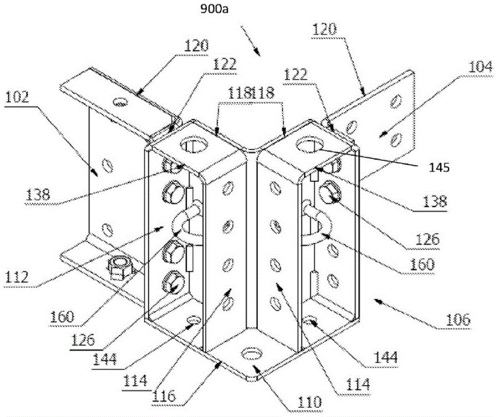
The present invention relates to a system for off-site construction of buildings, and also discloses a connector 100A, 900A for use in such a system, a method of making such a connector, and a method using the same method of system construction.
Description
Technical Field
The present invention relates to a system for off-site (offset) construction of buildings. A connector for use in such a system is also disclosed, as well as a method of manufacturing such a connector and a method of construction using the system.
Background
It is increasingly desirable to accelerate the construction of buildings by providing prefabricated components that can be manufactured off-site in a factory before being transported to a construction site and assembled into a complete building. Such prefabricated buildings have the significant advantage that the construction time of the building is minimised and the manufacturing costs can be minimised by using a common set of components for many different buildings. These construction methods are particularly useful in government-built buildings (such as schools) because the utility and cost of construction are typically two of the most important features of building codes.
The uniformity of the components also allows a single specification to be used in a plurality of different buildings. For example, it may be advantageous to provide each component of a building (i.e., post, connector, floor, wall, etc.) with a single shape, size, thickness, or other attribute. In this way, the manufacture of the building can be truly optimized.
To further simplify the manufacturing and assembly process, it may be desirable to provide a limited number of components that can be used and/or perform multiple tasks in many different ways.
Disclosure of Invention
According to a first aspect, there is provided a connector block for off-site construction of a building, comprising:
a first support element (button element) and a second support element defining a first locating portion and a second locating portion, respectively, configured to receive a first structural element and a second structural element extending at a transverse angle (preferably at a right angle) to each other;
two support elements, together defining a third positioning portion configured to receive a third structural element extending orthogonally to the (orthogonally) first and second structural elements.
The connector block is thus capable of providing orthogonal connections of up to three orthogonal structural elements. This enables the connector block to be used as a corner fitting in various forms of off-site construction techniques, for example:
3D major structural system, systematic approach based on volume building, comprising production of three-dimensional units under controlled factory conditions before final installation.
2D primary structural system, systematic approach using flat plate units for foundation floor, wall and roof structures of different materials, produced in a factory environment and assembled at the final work surface to produce the final three-dimensional structure.
Non-systematized primary structure, use of prefabricated structural members that are not essentially field work surface built and are not part of a systematized design.
The connector block may comprise a substrate forming a base of each support element and interconnecting the support elements.
Thus, the substrate not only provides additional strength and/or rigidity to the support elements, but also serves to interconnect the support elements such that the support elements are supported by each other.
The base plate may define a portion of the third locating portion, for example a base of the third locating portion.
Thus, the base plate may assist in locating the structural element within the locating portion and/or provide an area to which the structural element may be secured once located.
The base plate may include an aperture defining a lifting point for the connector block.
The lifting points may be used to attach fixings to locate the connector block during construction. This may be useful prior to the connection of any structural element, and also when the connector block has been attached to a structural element and thus forms part of a larger module or structure.
The connector block may comprise at least one attachment element, each attachment element being configured to connect to one of the first and second support elements in a selected one of two orientations, each attachment element being configured to provide a connection between one of the support elements and the structural element.
The use of an attachment element may enhance the connection between the support element and the structural element to which the attachment element is attached.
The attachment element may be L-shaped or substantially L-shaped. This means that the attachment to the structural element provided by the attachment element may be on a different side of the structure than is possible when connecting the structural element directly to the support element.
The attachment element may comprise a plurality of attachment faces. In case the attachment element is L-shaped, there may be two attachment faces positioned at right angles to each other. Each attachment face may comprise a hole for receiving a connector to attach the attachment element to the support element and/or the structural element. The attachment face configured to connect to the structural element may include more holes — having more holes than the attachment face configured to connect to the support element. For example, the attachment face configured to connect to the structural element may comprise four holes, and the four holes may be in a rectangular arrangement, and the attachment face configured to connect to the bracing element may comprise three holes, and the three holes may be in a linear arrangement.
The attachment face configured to connect to the structural element may have a larger area than the attachment face configured to connect to the support element, for example, may be twice as large or approximately twice as large. This may provide greater stability to the connection.
The support element may comprise a hole for receiving a connector for connection to the attachment element and/or the structural element. These holes may be configured to align with corresponding holes in the attachment element and/or the structural element.
The connector may be a bolt.
The bore may include an integrated nut configured to engage the bolt. By providing an integral nut, the attachment of the bolt can be made simpler, for example, using a single tool.
Each support element may comprise a locator for locating the accessory on the connector block. The accessory may include a bracket, a locating pin, or a lifting and handling device.
The positioner may include a positioner tube formed between a top surface and a bottom surface of the connector tube. The positioner tube may provide a simple connection for attachment.
The positioner tube may be open at an upper end and at least partially closed at a lower end.
Each positioner tube may be at least partially enclosed at a lower end by a base plate of the connector block.
The connector block may further comprise a support plate positioned within each support element for supporting the positioner tube partially along the length of the positioner tube.
The support plate may not only provide support for the positioner tubes, preventing movement of the positioner tubes or misalignment of the positioner tubes, but may also provide enhanced or enhanced rigidity to the support elements on which the support plate is positioned.
The connector may include a U-shaped bracket to provide a connection point for safe manual manipulation of the connector or assembled structural element. The U-shaped bracket can be used to guide the structural elements into position, either by using ropes, wires, straps and levers, or as a means of securing the 3D or 2D assembly to a delivery vehicle to ensure safe transport.
Each support element may comprise two opposing side walls, one of the opposing side walls defining the first locating portion and the other of the opposing side walls defining a part of the third locating portion.
Each support element may comprise a third side wall interconnecting the opposing side walls.
The presence of the third side wall may provide additional strength and/or rigidity to each support element. Access to the interior of the support element may be ensured by not providing the fourth side wall.
Each third side wall may be located on an inner side of the connector block.
By positioning the third side wall on the inner side, the outer side may be kept open for easy access to the interior of the support element, e.g. for access to connections or for passing wiring.
The connector block may be L-shaped or substantially L-shaped. Such a shape may provide strength to the connector block while ensuring that the structural element can be attached in the correct orientation. Further, the L-shaped connector blocks may be oriented in different ways depending on the apex of the module to which the L-shaped connector block is to be attached.
The connector block may be formed from a plurality of plates.
The plate may be a metal plate, such as steel or any other suitable metal.
The plate may have a single gauge or thickness.
The support element may be formed by a box portion, which may be a standard box portion.
The plates may be bent into shape prior to assembly to the other plates of the connector block.
The plates may be joined by at least one male and female dovetail (mortise and ten joint) joint. These may provide good strength to the connector block while maintaining a simple structure.
Alternatively or additionally, the plates may be welded together. The welding may enhance the connection strength of the plates. The plates may be welded together individually without other forms of joining. Alternatively, the connector may be formed using a single piece of manufacture (e.g., a mold or casting).
The connector block may be achiral, i.e. substantially symmetrical, such that a single connector can be used on both the left hand side and the right hand side of the structural assembly.
Similarly, the connector block may be inverted so that the base plate becomes a cover when used in a roof or roof panel assembly.
Additional integration nuts may be secured to the connector block to suit specific site connection requirements, the base platform of the connector block is unaffected by the addition of the additional integration nuts, thereby ensuring greater flexibility.
According to a second aspect, there is provided a system for off-site construction of a building, comprising:
a plurality of structural elements;
at least one connector block configured to interconnect structural elements;
wherein the at least one connector block is configured to provide releasable connection between the plurality of structural elements in three orthogonal directions.
Thus, a simple, releasable system is provided for off-site construction of buildings.
The releasable connection may be provided by a connector (e.g. a bolt).
The bolt may be received by an integral nut of each connector block.
By providing an integral nut, the attachment of the bolt can be made simpler, for example, by using a single tool.
The connector block may be made of a plurality of plates. The plate may be a metal plate, such as steel or any other suitable metal.
Forming the connector piece from a plurality of plates provides a simple and cost effective method of providing a connector piece.
The plates may be joined by at least one male-female dovetail joint. These may provide good strength to the connector block while maintaining a simple structure.
Additionally or alternatively, the plates may be welded together. The welding may enhance the connection strength of the plates. The plates may be welded together individually without other forms of joining.
The panels may be of a single gauge (gauge) or thickness.
The support element may be formed by a box portion, which may be a standard box portion.
The structural element may comprise an elongate member. The elongate member may take the form of a beam or strut and may be configured to receive additional portions of the system.
The system may further comprise at least one floor section, roof section and/or wall section connected to the structural element to form a floor, roof and/or wall.
Thus, the system may provide a complete building module comprising structural elements, walls, floors and ceilings. These building modules may form a building individually or in groups.
According to a third aspect, there is provided a method of manufacturing a connector block according to the first aspect, the method comprising the steps of:
the first support element and the second support element are formed by a plurality of plates joined together.
The plates may be joined together using male and female dovetail joints. These joints can be simply and inexpensively formed in the plate member.
The method may include the further step of welding the plates together. This may provide additional strength to the connector block.
The method may comprise the further step of forming holes in the plate. The step of forming the holes in the plate may be performed before the step of forming the first and second support elements. Forming the holes prior to forming the support elements simplifies construction because when all of the holes are in the same plane, all of the holes can be formed, thus avoiding drilling or otherwise forming holes in multiple different directions.
According to a fourth aspect, there is provided a method of constructing a structure using at least one connector block according to the first aspect, the method comprising:
a plurality of structural elements are connected together with at least one connector block.
The method may further comprise connecting a first structural element to a first locating portion of the at least one connector block and/or connecting a second structural element to a second locating portion of the at least one connector block.
The method may also include connecting a third structural element to a third locating portion of the at least one connector block.
Prior to connecting the first and second structural elements, the method may comprise the step of connecting an attachment element to at least one support element of at least one connector block, the attachment element being connected to the structural elements.
The method may further comprise the step of joining at least one floor section, wall section or roof section to form a floor, wall or roof respectively.
Drawings
The disclosure will now be discussed with reference to the accompanying drawings, in which:
fig. 1a and 1b are perspective and plan views of a connector according to the present disclosure;
FIG. 2 is an exploded view of the connector of FIGS. 1a and 1b, showing all of the components of the connector;
FIG. 3 is a perspective view of a connector according to the present disclosure, the connector being in a roof/roof orientation, i.e., inverted relative to the connector of FIGS. 1a and 1 b;
FIG. 4 is a perspective view of a pair of connectors in a portion of a floor and roof assembly showing additional structural members shown as an example of structural members that may be secured by connector blocks;
FIG. 5 shows three stages of construction of a building using a system according to the present disclosure;
FIG. 6 is a flow chart illustrating the steps involved in a method of manufacturing a connector according to the present disclosure;
figure 7 is a flow chart showing the steps involved in a method of constructing a building using the system of the present disclosure,
figure 8 shows a number of different attachments to the support of the connector block of the present disclosure,
figures 9 and 10 show a perspective view and a plan view respectively of a second type of connector according to the present disclosure,
fig. 11 is a perspective view of the pair of connectors shown in fig. 9 and 10 in a portion of a floor and roof assembly, the view in fig. 11 being similar to the view in fig. 4,
figure 12 is a plan view of the four connectors shown in figures 9 and 10 in a portion of a floor and roof assembly,
FIG. 13 is a perspective view of a portion of the four connectors and floor and roof assembly of FIG. 12, an
Fig. 14 is a side view of the connector shown in fig. 9 connected to a first vertical structural element and a second non-vertical structural element.
Detailed Description
Referring first to fig. 1 and 2, a connector block 100a is shown. The connector block 100a includes a first support element 102 and a second support element 104, the first support element 102 and the second support element 104 defining a first positioning portion 106 and a second positioning portion 108, respectively. The first positioning portion 106 and the second positioning portion 108 are positioned at right angles to each other so that they can accommodate a first structural element 1006 and a second structural element 1006 (see fig. 4) extending in orthogonal directions. The connector block 100a may thus be used in a corner position of a building or in a part of a building.
The first and second support elements 102, 104 together also define a third location portion 110 located between the first support element 102 and the second support element 104. The third positioning portion 110 is configured to receive a third structural element 1010 (refer to fig. 4) orthogonal to the positions of the first and second structural elements. Thus, the connector block 100a may connect three structural elements together to form an apex of a building or a portion of a building.
As shown in fig. 1a and 1b, a first structural element will extend from the first support element 102 in a direction towards the left side of the first support element 102, a second structural element will extend from the second support element 104 in a direction towards the right side of the second support element 104, and a third structural element will extend upwards between the first and second support elements 102, 104. Of course, different orientations may be used to connect the structural elements if desired.
Each support element 102, 104 comprises two opposing side walls 112, 114. The outer opposing side walls 112 define or form the boundaries of the first or second positioning portions 106, 108, respectively, while the inner opposing side walls 114 of each support element 102, 104 define or form the boundaries of the third position portion 110.
A base plate 116 is provided which base plate 116 both provides a lower wall for each of the first and second support elements 102, 104 and interconnects both. Thus, the substrate 116 helps to provide stability to the connector block 100 a. The base plate 116 is substantially L-shaped, the width of the base plate 116d being equal or substantially equal to the width of the support members 102, 104, forming a solid base for the support members 102, 104.
Each support element 102, 104 further comprises a third side wall 118. In the illustrated embodiment, the third side wall 118 interconnects two opposing side walls 112, 114 of each support element 102, 104 that are located inside the L-shaped connector block 100 a. The side of the support elements 102, 104 that is outside the connector block 100a has no side walls to allow access to the interior of each support element 102, 104. In alternative embodiments, removable sidewalls or partial sidewalls may be included so that access to the interior of the connector block 100a may be maintained.
The first and second positioning portions 106, 108 include attachment elements 120a, 120b, respectively, to facilitate connection of the structural elements. The attachment elements 120a, 120b have an L-shaped cross-section and are releasably connected to the respective support elements 102, 104. The L-shape allows the attachment elements 120a, 120b to be attached to the support elements 102, 104 and the structural element simultaneously, each connection being formed on a different surface of the attachment elements 120a, 120 b. Since the attachment elements 120a, 120b are releasably connected to the support elements 102, 104, the attachment elements 120 may be of the same or different size and/or may be oriented in two different positions depending on the requirements of the connector block 100a, the two different positions being provided by rotating the first surfaces 122 of the attachment elements 120a, 120b connected to the support elements 102, 104 by 180 °.
By changing the connection position of the attachment elements 120a, 120b, the position of the second face 124 of the connection elements 120a, 120b connected to the structural element can be changed. In this way, the location of attachment to the structural element may be different. This may be particularly advantageous where multiple adjacent connector blocks 100a are required to be attached to a single structural element.
It will also be apparent that the second face 124 of the attachment elements 120a, 120b is longer than the first face 122. This allows for a stronger connection to the structural element, for example by providing a greater number of connectors without requiring larger support elements 102, 104.
The attachment elements 120a, 120b are each attached to their respective support element 102, 104 by a connector (e.g., bolt 126). It should be understood that the space defined between support walls 112 and 114 forms a space to fit bolt 126 into attachment elements 120a, 120 b. In the illustrated case, four bolts 126 are used to connect the attachment element 120a to the first support element 102, while two bolts 126 are used to connect the attachment element 120b to the second support element 104. This is because the height of the attachment element 120a connected to the first support element 102 is greater than the height of the attachment element 120b connected to the second support element 104. Of course, a greater or lesser number of bolts 126 may be used depending on the desired strength of the connection, the size of the connection block 100a or the attachment elements 120a, 120b, and the size of the bolts 126 themselves.
Each bolt 126 passes through a hole 128 in the attachment element 128 and a hole 130 in the support elements 102, 104. A washer 132 is disposed between each bolt head and the attachment element 120. In the illustrated embodiment, the nut 134 connected to each bolt 126 is provided separately, however they may be provided integrally as part of the support element 102, 104, i.e. the nut 134 is attached to or formed as part of the inner surface of the outer sidewall 112 of the support element 102, 104. By providing the bolt 126 integral with the outer wall 112 or fixedly mounted to the outer wall 112, the bolt 126 may be screwed into the nut 134 without the need to separately retain the bolt 126, thereby making attachment of the attachment element 120 simpler for a user.
The base plate 116 may also form a lower boundary of the first and second support elements 102, 104 to provide a lower boundary and definition of the third positioning portion 110. Thus, the substrate 116 serves to provide stability to the connector block 100a, so that the substrate 116 interconnects the two support elements 102, 104. Further, as a lower boundary of the third positioning portion 110, the substrate 116 provides a base on which the structural elements within the third positioning portion 110 may be located.
In this embodiment, the base plate 116 further includes attachment points 136 in the form of holes. The attachment points 136 allow the connector block 100a to be connected to, for example, a lifting device. When in place in the structure, this means that the connector block 100a and connected structural elements can be easily lifted for assembly or repositioning. Additionally or alternatively, the attachment points 136 may provide points at which adjacent connector blocks 100a in the assembly may be joined together by fasteners (such as bolts or other suitable fastening means).
Each support element 102, 104 further comprises a top plate 138, which top plate 138 interconnects each side wall, comprising two opposite side walls 112, 114 and a third side wall 118. The top plate 138 includes an opening 140 to enable vertical connection between the connector blocks 100 a. The top plate 138 may also include guide tubes (not shown in this embodiment) to help guide the bolts into place. The positioning tube will extend from the top plate 138 in a plane parallel to the plane of the opposing sidewalls 112, 114 and terminate on the base plate 116. The positioning tube will rest on the substrate 116 and not pass through the substrate 116. However, a (small) aperture 144 is formed in the base plate 116, which (small) aperture 144 allows access to the interior of the positioning tube.
The connector may include a U-shaped bracket 160 to provide a connection point for safe manual manipulation of the connector or assembled structural element. U-shaped brackets may be used to guide the structural elements into position using various methods. As shown in fig. 8, a cord 2000, a wire 2002, a strap (not shown), and a lever 2004 are shown. The U-shaped bracket may also or alternatively be used as a means of securing a 3D or 2D assembly to a delivery vehicle to ensure safe transport.
The connector block 100a is formed of a plurality of plates. The base plate 116 is flat, the side walls 112, 114 and the top plate 138 together form a U-shape, and the third side wall 118 forms an L-shaped element. The U-shaped and L-shaped elements may be cast, machined or bent from flat stock. Providing these components as shaped elements ensures a simple manufacture of the connector block 100 a. Each of the elements 112, 114, 118 and 138 may be provided as a flat plate and may be manufactured to form the entire connector block. The attachment element 120 is L-shaped and may be cast or machined. However, the attachment element 120 is preferably bent from a flat blank in order to further simplify the manufacturing process.
Each panel is connected to the other panels by a series of male and female dovetail joints. Thus, the plates include projections and/or slots that may be engaged to provide a male-female dovetail joint. Once in place, the plates may be welded together to provide additional strength and/or rigidity to the connection block 100 a.
The connector block is achiral, that is, it is symmetrical, enabling a single connector to be used on both the left hand side and the right hand side of the structural assembly.
Similarly, connector block 100b may be inverted when bottom plate 116 now becomes a cover for a roof or roof panel assembly. This can be seen in fig. 3 and 4.
Additional integral nuts may be secured to the connector block to suit specific site connection requirements, the base platform of the connector block being unaffected by the additional integral nuts, thereby ensuring greater flexibility.
Referring to fig. 4, an exemplary attachment is shown that includes a locating pin 180, which locating pin 180 may be secured to connection block 100b to allow vertical alignment and lateral constraint when the subassembly is connected. Bolts 181 arranged through the apertures 144 provide a secure vertical connection between the connecting blocks, which bolts 181 may be used to prevent a gradual collapse of the building. These examples illustrate the flexibility of the connection block and are not an exhaustive list of potential connection options.
The connector block 100a is designed to efficiently distribute the load from the horizontal structural member 1006 to the vertical structural member 1010.
An assembly 1000 is shown in fig. 5. The left-most drawing shows a backplane assembly 1002 that includes four connector blocks 100a, each connector block 100a disposed at a corner of a backplane 1004. The horizontal structural elements 1006 use bolts to interconnect the connector blocks 100a to form a rectangular structure. The horizontal structural element 1006 is thus attached to the first and second locating portions 106, 108 of each connector block 100 a. A floor section 1008 is then provided. A floor portion 1008 is attached to the structural element 1006. In the depicted backplane assembly, four backplane sections 1008 are provided, but different numbers or sizes of backplane sections may be provided as desired. Structural element 1006 may be formed from any structurally strong material, such as steel.
At the next stage, as shown in the middle picture, four vertical structural elements 1010 have been connected to the connector block 100 a. The vertical structural member 1010 is fixed to the third position part 110 of each connector block 100a by a plurality of bolts. On one end of the floor assembly 1002, a wall portion 1012 is connected to the horizontal structural element 1006 and the two vertical structural elements 1010. The wall portion 1012 includes a window 1014, although a solid wall portion may alternatively be provided.
Finally, in a third stage, the top plate assembly 1014 is attached to the four vertical structural elements 1010. The top plate assembly 1014 includes nine top plate portions 1016, the nine top plate portions 1016 being supported by the four horizontal structural elements 1006. The horizontal structural elements 1006 are interconnected in the same manner as those previously described, with the connector block 100b forming each vertex of the top plate assembly 1014. The connector blocks 100b of the top plate assembly 1014 are inverted as compared to those of the bottom plate assembly 1002 so that the third locating portion 110 of each connector block 100b can receive the vertical structural element 1010.
The complete assembly 1000, including the bottom plate assembly 1002, the top plate assembly 1014, and the wall portion 1012, may be attached to similar or identical assemblies by connector blocks 100a, 100 b. For example, the connector blocks 100a, 100b may be attached directly to other connector blocks 100a, 100b, such as using connectors that pass through holes or apertures in the connector blocks 100a, 100b, or may be attached directly to other structural elements 1006, 1010. In this manner, assembly 1000 may be part of a larger modular structure. Larger modular structures may form buildings such as residential buildings, commercial buildings, or civic buildings such as schools.
Fig. 6 shows a method of manufacturing the connector block shown in fig. 1 and 2. In a first step S10, a plurality of panels is provided. These plates are shaped by any suitable manufacturing method so that they have the correct shape to form the side walls, top plate, base plate, support plate, attachment elements or any other part of the connector block. The formation of the panels includes any connection features, such as portions of the male and female dovetail joints shown in fig. 1 and 2.
In step S12, the plate may be machined or otherwise processed to form holes in the plate. Advantageously, the formation of the holes will be performed before the boards are assembled into the final shape of the connector adapter 100, to simplify the manufacturing process. This step S12 follows the first step S10.
In step S14, once the plates have been manufactured, they are joined together to form the shape of the connector block 100. The engagement of the connector block 100 shown in fig. 1a, 1b and 2 is provided using a male-female tenon joint. If other types of joints are used in the connector block 100, the method will include joining the plates using any type of joint provided by the connector block. To ensure that the connection is permanently maintained, the plates of the connector block 100 of the present disclosure are also welded together along their edges. This is shown in the next step S16 of fig. 6.
In fig. 7, a method of building a structure using at least one connector block is shown. In step S22, the structural element is connected to the or each connector block 100. These structural elements may be connected to the first positioning portion 106, the second positioning portion 108 or the third positioning portion 110, depending on the orientation of the structural element that needs to be positioned. In the case where the connector blocks 100 are as shown in fig. 1 and 2, the structural member is connected to each connector block 100 by bolts.
Prior to this step of using the attachment elements, it may be necessary to connect one or more attachment elements 120 to the connector block 100. Thus, there will be an earlier step S20 whereby the attachment element 120 is connected to the support elements 102, 104 of the connector block 100. The attachment element 120 may alternatively be attached to the connector block 100 after the structural element has been attached to the attachment element 120, if the design of the connector block 100 allows.
Once the structural elements have been connected to the connector block 100, it may be desirable to provide one or more walls, ceiling or floor to the structure. In this case, in another step S24, the bottom plate portion 1008, the wall portion 1012, or the top plate portion 1016 may then be secured or attached to the structural element.
Referring to fig. 10, the first and second locating portions 106, 108 of the connector 100a are configured at right angles to each other (as are the support portions-see fig. 9) so as to receive first and second structural elements that extend at right angles, i.e., the horizontal elements 1006 are angularly spaced apart by 90 degrees in the horizontal plane. However, while the embodiments in the preceding paragraphs are popular-due to the popular shape of the building structure shown in fig. 8, it will be appreciated that connectors having support elements arranged at other lateral angles to each other (and other portions of the correspondingly arranged connectors 100a) allow the horizontal elements to be angularly spaced apart in the horizontal plane at angles other than 90 degrees, for example 120 degrees, to engage successive horizontal elements and connectors in a hexagonal configuration in plan view, or 60 degrees to engage successive horizontal elements and connectors in a triangular configuration in plan view.
In fig. 9 and 10, a second type of connector 900a is shown.
One difference between the connector 100a of fig. 1a and the connector 900a of fig. 9 is that the two apertures (144 and unnumbered-for fasteners 181 and 180, respectively) in the supporting lower wall are replaced by a single aperture 144 (for a corresponding fastener 181, as shown in fig. 11). The pin 180 in fig. 4 provides a structural bond, which is not always necessary. Accordingly, the connector 900a is simplified and the width of the support members 102, 104 may be reduced. The fastener 181 remains the primary vertical stabilizing structural connection (part a according to uk building code) for a disproportionate fold. This arrangement also allows a 50% reduction in components. Having a single fastener 190 (see fig. 11) connection within each third structural element 1010 and having attachment points 136 (as shown in fig. 12) on each connector 900a allows for easier installation in a four connector arrangement, as positioning is only required at four points. A single member 190 is contemplated, the single member 190 also extending sufficiently vertically to position the upper and lower connectors 900a in fig. 11, and optionally the upper and lower vertical rods in fig. 11.
The support upper wall 102 includes two apertures (144 and not numbered-for fasteners 181 and 180 respectively) and is also replaced by a single (larger) aperture 145. The aperture 145 is used to access the space between 112 and 114. The apertures 145 may be used for insertion of a tool to facilitate drawing the side-by-side connectors 900a (and thus the modules) together.
The attachment element 120a is U-shaped in cross-section, the attachment element 120a being reinforced by adding plates at the top and bottom. The upper and lower plates of the attachment element 120a each have apertures to provide more connection options. This redistributes the force from the beam 1006 more evenly into the connector block 900a to limit local buckling in the block.
In fig. 11, a pair of connectors 900a are shown in fig. 9 and 10 in a portion of a floor and roof assembly, the view in fig. 11 being similar to the view in fig. 4. Each horizontal structural element 1006 includes an aperture 1200 in its upper surface.
In fig. 12 and 13, four of the connectors 900a shown in fig. 9 and 10 are disposed in a portion of the floor and roof assembly.
Adjacent connectors may be connected by a plate (not shown for clarity) secured through adjacent first and second apertures 144, 144.
The tops of adjacent horizontal structural elements 1006 may be connected in situ by plates 1202, the plates 1202 being secured through apertures 1200 using countersunk bolts 1204, 1206. The panel 1202 also serves as a horizontal solid connection for disproportionate folding (according to uk building code part a). Further, an aperture 1200 is provided in the bottom of the horizontal structural element 1006.
The design of the connector 100a, 900a also allows the position of the attachment elements 120a and 120b to be switched in case an increased structural rigidity is required. This means that when the connector 900a is turned 180 ° relative to the other connector 900a, as with the two connectors 900a shown in fig. 11, which in turn causes the size of the horizontal member 1006 to be reversed, the horizontal member 1006 can be accommodated by the attachment elements 120a, 120b, which means that the webs of adjacent beams 1006 of the same size can be arranged "back to back", allowing horizontal bolts to be installed through apertures 1220 in the web sections 1006, as shown in fig. 13, thereby improving the combined structural performance of the horizontal structural elements 1006.
Referring to fig. 14, a connector 900a may be connected to a first vertical structural element 1010 and a second non-horizontal structural element 1006. Referring to fig. 9, this is done by arranging the holes in the attachment portion 120a of the second structural element 1006 so that they do not lie in a vertical line, but are offset from the vertical line at a suitable angle. As a result, three bolts 1208 are offset from a vertical line at appropriate angles, and three bolts 1210 are offset from a vertical line at appropriate angles. Thus, the lower surface 1016 of the non-horizontal structural element 1006 is inclined with respect to horizontal, as indicated by the dashed line. The offset is variable to account for different roof pitch requirements.
The claims (modification according to treaty clause 19)
1. A connector block (100a) for off-site construction of a building, comprising:
a first support element (102) and a second support element (104), the first support element (102) and the second support element (104) defining a first positioning portion (108) and a second positioning portion (106), respectively, configured to receive a first structural element and a second structural element, respectively, extending at a lateral angle with respect to each other, preferably at a right angle with respect to each other;
the first support element (102) comprising a first side wall (112) opposite a second side wall (114), the first side wall (112) and the second side wall (114) defining an access space therebetween for a connector (126, 180, 181) to be accessed,
the second support element (104) comprising a first side wall (112) opposite a second side wall (114), the first side wall (112) and the second side wall (114) defining an access space therebetween for a connector (126, 180, 181) to be accessed,
the second side wall (114) of the first support element (102) and the second side wall (114) of the second support element (104) together define a third locating portion (110) configured to receive a third structural element extending transversely, preferably orthogonally, to the first and second structural elements.
2. The connector block of claim 1, wherein the connector block comprises a base plate forming a base of each support element and interconnecting the support elements.
3. The connector block of claim 2, wherein the substrate defines a portion of the third positioning portion.
4. The connector block of claim 2 or 3 wherein the base plate includes an aperture defining a lifting point for the connector block.
5. The connector block of any preceding claim, further comprising at least one attachment element (120a, 120b), each attachment element being configured to connect to one of the first and second support elements in a selected one of two orientations, each attachment element being configured to provide a connection between one of the support elements and a structural element.
6. The connector block of any preceding claim, wherein the support element comprises a bore for receiving a connector for connection to an attachment element and/or a structural element, optionally wherein the connector is a bolt, further optionally wherein the bore comprises an integral nut configured to engage with the bolt.
7. The connector block of any preceding claim, wherein each support comprises two opposing side walls, one of the opposing side walls defining the first locating portion and the other of the opposing side walls defining a portion of the third locating portion.
8. The connector block of claim 7, wherein each support element comprises a third side wall interconnecting the opposing side walls.
9. The connector block of claim 8 wherein each third sidewall is located on an interior side of the connector block.
10. The connector block of any preceding claim, wherein the connector block is L-shaped or substantially L-shaped.
11. A system for off-site construction of a building, comprising:
a plurality of structural elements;
the at least one connector block of any one of the preceding claims, the connector block being configured to interconnect the structural elements.
12. The system of claim 11, wherein the releasable connection is provided by a connector, optionally wherein the connector is a bolt, further optionally wherein the bolt is receivable by an integral nut of each connector.
13. The system of any one of claims 12 or 12, wherein the connector block is made of a plurality of plates, optionally wherein the plates are joined by at least one male-female dovetail joint.
14. The system of claim 13, wherein the plates are welded together.
15. The system of any one of claims 11 to 14, wherein the structural element comprises an elongate member.
16. The system according to any one of claims 11 to 15, further comprising at least one floor portion, roof portion and/or wall portion connected to the structural element to form a floor, roof and/or wall, respectively.
17. A method of manufacturing a connector block according to any of claims 1 to 10, the method comprising the steps of:
the first support element and the second support element are formed from a plurality of plates joined together.
18. The method of claim 17, wherein the plates are joined together using a male and female dovetail joint.
19. A method according to claim 17 or 18, further comprising the step of welding the plates together.
20. A method according to any one of claims 17 to 19, further comprising the step of forming holes in the plate.
21. A method of building a structure using at least one connector block according to any one of claims 1 to 10, the method comprising:
at least one connector block is used to connect a plurality of structural elements together.
22. The method of claim 21, further comprising connecting a first structural element to a first locating portion of the at least one connector block and/or connecting a second structural element to a second locating portion of the at least one connector block.
23. The method of claim 22, further comprising connecting a third structural element to a third locating portion of the at least one connector block.
24. A method according to any of claims 21-23, wherein before connecting the first and second structural elements, the method comprises the step of connecting an attachment element to at least one of the support elements of the at least one connector block, the attachment element being connected to the structural element.
25. The method of any one of claims 21 to 24, further comprising the step of joining at least one floor section, wall section or roof section to form a floor, wall or roof, respectively.
Statement or declaration (modification according to treaty clause 19)
said first support element (102) comprising a first side wall (112) opposite a second side wall (114), said first side wall (112) and said second side wall (114) defining an access space therebetween for a connector (126, 180, 181) to be accessed,
the second support element (104) comprises a first side wall (112) opposite a second side wall (114), the first side wall (112) and the second side wall (114) defining an access space, … … ", therebetween for a connector (126, 180, 181) to be accessed.
None of the references mentioned in the international search report disclose a similar "room for entry".
The first and second support elements 102, 104 advantageously have an enhanced functionality.
Advantageously, the connector block 100a as claimed in claim 1 is advantageous over the mentioned reference documents in that the access space allows the connectors 126, 180, 181 to be received inside the support elements 102, 104.
Claims (25)
1. A connector block for off-site construction of a building, comprising:
a first support element and a second support element defining a first locating portion and a second locating portion, respectively, configured to receive a first structural element and a second structural element extending at a transverse angle relative to one another, preferably at a right angle relative to one another;
the two support elements together define a third locating portion configured to receive a third structural element extending orthogonally to the first and second structural elements.
2. The connector block of claim 1, wherein the connector block comprises a base plate forming a base of each support element and interconnecting the support elements.
3. The connector block of claim 2, wherein the substrate defines a portion of the third positioning portion.
4. The connector block of claim 2 or 3 wherein the base plate includes an aperture defining a lifting point for the connector block.
5. The connector block of any preceding claim, further comprising at least one attachment element, each attachment element being configured to connect to one of the first and second support elements in a selected one of two orientations, each attachment element being configured to provide a connection between one of the support elements and a structural element.
6. The connector block of any preceding claim, wherein the support element comprises a bore for receiving a connector for connection to an attachment element and/or a structural element, optionally wherein the connector is a bolt, further optionally wherein the bore comprises an integral nut configured to engage with the bolt.
7. The connector block of any preceding claim, wherein each support comprises two opposing side walls, one of the opposing side walls defining the first locating portion and the other of the opposing side walls defining a portion of the third locating portion.
8. The connector block of claim 7, wherein each support element comprises a third side wall interconnecting the opposing side walls.
9. The connector block of claim 8 wherein each third sidewall is located on an interior side of the connector block.
10. The connector block of any preceding claim, wherein the connector block is L-shaped or substantially L-shaped.
11. A system for off-site construction of a building, comprising:
a plurality of structural elements;
the at least one connector block of any one of the preceding claims, the connector block being configured to interconnect the structural elements.
12. The system of claim 11, wherein the releasable connection is provided by a connector, optionally wherein the connector is a bolt, further optionally wherein the bolt is receivable by an integral nut of each connector.
13. The system of any one of claims 12 or 12, wherein the connector block is made of a plurality of plates, optionally wherein the plates are joined by at least one male-female dovetail joint.
14. The system of claim 13, wherein the plates are welded together.
15. The system of any one of claims 11 to 14, wherein the structural element comprises an elongate member.
16. The system according to any one of claims 11 to 15, further comprising at least one floor portion, roof portion and/or wall portion connected to the structural element to form a floor, roof and/or wall, respectively.
17. A method of manufacturing a connector block according to any of claims 1 to 10, the method comprising the steps of:
the first support element and the second support element are formed from a plurality of plates joined together.
18. The method of claim 17, wherein the plates are joined together using a male and female dovetail joint.
19. A method according to claim 17 or 18, further comprising the step of welding the plates together.
20. A method according to any one of claims 17 to 19, further comprising the step of forming holes in the plate.
21. A method of building a structure using at least one connector block according to any one of claims 1 to 10, the method comprising:
at least one connector block is used to connect a plurality of structural elements together.
22. The method of claim 21, further comprising connecting a first structural element to a first locating portion of the at least one connector block and/or connecting a second structural element to a second locating portion of the at least one connector block.
23. The method of claim 22, further comprising connecting a third structural element to a third locating portion of the at least one connector block.
24. A method according to any of claims 21-23, wherein before connecting the first and second structural elements, the method comprises the step of connecting an attachment element to at least one of the support elements of the at least one connector block, the attachment element being connected to the structural element.
25. The method of any one of claims 21 to 24, further comprising the step of joining at least one floor section, wall section or roof section to form a floor, wall or roof, respectively.
Applications Claiming Priority (3)
| Application Number | Priority Date | Filing Date | Title |
|---|---|---|---|
| GB1909855.7A GB2586007B (en) | 2019-07-09 | 2019-07-09 | Multi-functional connector |
| GB1909855.7 | 2019-07-09 | ||
| PCT/IB2020/056486 WO2021005561A1 (en) | 2019-07-09 | 2020-07-09 | Multi-functional connector |
Publications (2)
| Publication Number | Publication Date |
|---|---|
| CN114599842A true CN114599842A (en) | 2022-06-07 |
| CN114599842B CN114599842B (en) | 2024-04-30 |
Family
ID=67623218
Family Applications (1)
| Application Number | Title | Priority Date | Filing Date |
|---|---|---|---|
| CN202080062517.7A Active CN114599842B (en) | 2019-07-09 | 2020-07-09 | Multifunctional connector |
Country Status (7)
| Country | Link |
|---|---|
| US (1) | US12180697B2 (en) |
| EP (1) | EP3997278A1 (en) |
| JP (1) | JP7589220B2 (en) |
| CN (1) | CN114599842B (en) |
| CA (1) | CA3145790A1 (en) |
| GB (1) | GB2586007B (en) |
| WO (1) | WO2021005561A1 (en) |
Families Citing this family (8)
| Publication number | Priority date | Publication date | Assignee | Title |
|---|---|---|---|---|
| GB2586007B (en) | 2019-07-09 | 2023-12-20 | Moonshine Investment Holdings Ltd | Multi-functional connector |
| GB2608661A (en) * | 2020-06-01 | 2023-01-11 | Sekisui House Kk | Joining hardware |
| USD983021S1 (en) * | 2021-01-13 | 2023-04-11 | Moonshine Investment Holdings Limited | Connector for connecting parts of a building structure |
| EP4444960A1 (en) * | 2021-03-25 | 2024-10-16 | Modulart | Volumetric modules |
| AU2022329267B2 (en) * | 2021-08-20 | 2024-03-21 | Anz Modular Limited | Universal modular connector |
| USD1120883S1 (en) * | 2024-04-19 | 2026-03-31 | Vince DUNDEE | Connector for a modular display structure |
| USD1083560S1 (en) * | 2024-06-04 | 2025-07-15 | Shanghai Shifu Industrial Development Co., Ltd | Corner piece for shipping container |
| US12454826B1 (en) * | 2025-02-18 | 2025-10-28 | Scott Record | Wall building system |
Citations (9)
| Publication number | Priority date | Publication date | Assignee | Title |
|---|---|---|---|---|
| CN1090007A (en) * | 1992-07-08 | 1994-07-27 | 埃科创新有限公司 | The construction method of a kind of building and used plate thereof and this building |
| WO2002023053A1 (en) * | 2000-09-13 | 2002-03-21 | Halfen Gmbh & Co. Kommanditgesellschaft | Connecting part for mounting rails |
| CN202055344U (en) * | 2011-04-22 | 2011-11-30 | 甘秀明 | Crossbeam node structure of building steel vertical pillar |
| CN205604471U (en) * | 2016-05-12 | 2016-09-28 | 中国矿业大学 | Novel assembly node of steel -pipe column and shaped steel roof beam |
| DE202016006174U1 (en) * | 2016-10-04 | 2016-12-06 | Gerhard Niedermeier | Corner connection of three bar-shaped elements, connecting element and storage, transport or frame or skeleton frame |
| CN108360683A (en) * | 2013-02-22 | 2018-08-03 | 维克托布洛克公司 | Section construction unit and construction and the method for transporting section construction unit |
| KR101904832B1 (en) * | 2018-05-04 | 2018-10-05 | 주식회사 미래정공 | The method for installing tents for building construction |
| CN109642429A (en) * | 2016-06-27 | 2019-04-16 | 洛戈Ip股份有限公司 | For connecting the device and method of timber flange |
| CN109736432A (en) * | 2018-12-19 | 2019-05-10 | 西安理工大学 | A kind of more high-rise assembled beam-column nodes with c-type cantilever segment |
Family Cites Families (30)
| Publication number | Priority date | Publication date | Assignee | Title |
|---|---|---|---|---|
| US682621A (en) * | 1901-04-30 | 1901-09-17 | Francis M Humphrey | Election-booth, knockdown structure, &c. |
| US1129658A (en) * | 1914-06-03 | 1915-02-23 | John H Foy | Corner-form for concrete construction. |
| US2168911A (en) * | 1937-05-07 | 1939-08-08 | Pierre H Meyer | Corner bracket for shelves |
| US3824750A (en) * | 1971-12-01 | 1974-07-23 | A Antoniou | Column connector system |
| US4267682A (en) * | 1979-05-07 | 1981-05-19 | Fowler Neal G | Building panel |
| GB2185272A (en) * | 1985-12-16 | 1987-07-15 | Sean Cavanagh | Demountable staging |
| US4758111A (en) * | 1986-11-21 | 1988-07-19 | Michael Vitta | Protective enclosures |
| DE3722849A1 (en) * | 1987-01-28 | 1988-08-18 | Stephan Wedi | Quick-construction partition wall for fitting up cubicles and partitions in sanitary areas and wet rooms |
| JPH0366303U (en) * | 1989-10-30 | 1991-06-27 | ||
| US5170977A (en) * | 1991-05-14 | 1992-12-15 | Mcmillan Connie L | Corner bracket |
| US5259685A (en) * | 1992-03-20 | 1993-11-09 | Simpson Strong-Tie Company, Inc. | Rigid intersection connection |
| US5349800A (en) * | 1993-04-19 | 1994-09-27 | Peng Sen Ming | Ceiling frame joint structure |
| JPH10102585A (en) * | 1996-10-01 | 1998-04-21 | Rongu Life:Kk | Frame construction method of wooden building and plate joint fitting used for it |
| JPH10152893A (en) | 1996-11-20 | 1998-06-09 | Sumitomo Forestry Co Ltd | Through column connector |
| US6247869B1 (en) * | 1997-11-05 | 2001-06-19 | Ultra Lite Products, Inc. | Tubing connector |
| US6004063A (en) * | 1997-11-13 | 1999-12-21 | Adams, Sr.; Randy B. | Adjustable 3-way scaffold fasteners |
| JP2004092241A (en) * | 2002-08-30 | 2004-03-25 | Izumi Naruse | Reinforcement method for wooden structure |
| KR20100001559U (en) * | 2008-08-04 | 2010-02-12 | 이충원 | Balcony pedestal |
| DE102011013159B4 (en) * | 2011-02-28 | 2013-02-07 | Rittal Gmbh & Co. Kg | Mounting frame for a control cabinet or a rack |
| KR101276642B1 (en) * | 2011-05-09 | 2013-06-19 | 문근환 | Corner connect device for assembly type structure |
| ITVI20110179A1 (en) * | 2011-07-04 | 2013-01-05 | Alfredino Moretto | METHOD FOR THE REALIZATION OF AN ELEMENT FOR THE CONNECTION OF TUBULAR ELEMENTS COMPONENTS A STRUCTURE AND CONNECTION ELEMENT REALIZED THROUGH THIS METHOD |
| JP2014040737A (en) * | 2012-08-22 | 2014-03-06 | Synapse International Kk | Connecting fitting and connecting structure |
| USD756202S1 (en) * | 2015-01-28 | 2016-05-17 | Roger Leduc | Tower frame bracket |
| AU2016247454A1 (en) * | 2015-04-15 | 2017-11-09 | Z-Modular Holding, Inc. | Connector for modular building structure |
| CN114809314B (en) * | 2015-08-14 | 2025-04-15 | Z-模块控股公司 | Connectors for modular buildings |
| ITUB20169951A1 (en) * | 2016-01-13 | 2017-07-13 | Federico Lestini | Modular building structure |
| KR101879034B1 (en) * | 2016-05-30 | 2018-07-17 | 주식회사 포스코 | Bracket and joint structure of column and beam using same |
| KR102309623B1 (en) * | 2018-02-22 | 2021-10-06 | 김순중 | Multidirectional connection brackets that can be assembled by interconnecting frame bars in multiple directions with one connection bracket |
| WO2020065474A1 (en) * | 2018-09-25 | 2020-04-02 | Clip-Lok International Limited | Racking arrangement and corner connector for use in a racking arrangement |
| GB2586007B (en) | 2019-07-09 | 2023-12-20 | Moonshine Investment Holdings Ltd | Multi-functional connector |
-
2019
- 2019-07-09 GB GB1909855.7A patent/GB2586007B/en not_active Ceased
-
2020
- 2020-07-09 CN CN202080062517.7A patent/CN114599842B/en active Active
- 2020-07-09 CA CA3145790A patent/CA3145790A1/en active Pending
- 2020-07-09 WO PCT/IB2020/056486 patent/WO2021005561A1/en not_active Ceased
- 2020-07-09 JP JP2022500853A patent/JP7589220B2/en active Active
- 2020-07-09 EP EP20756956.7A patent/EP3997278A1/en active Pending
- 2020-07-09 US US17/625,933 patent/US12180697B2/en active Active
Patent Citations (9)
| Publication number | Priority date | Publication date | Assignee | Title |
|---|---|---|---|---|
| CN1090007A (en) * | 1992-07-08 | 1994-07-27 | 埃科创新有限公司 | The construction method of a kind of building and used plate thereof and this building |
| WO2002023053A1 (en) * | 2000-09-13 | 2002-03-21 | Halfen Gmbh & Co. Kommanditgesellschaft | Connecting part for mounting rails |
| CN202055344U (en) * | 2011-04-22 | 2011-11-30 | 甘秀明 | Crossbeam node structure of building steel vertical pillar |
| CN108360683A (en) * | 2013-02-22 | 2018-08-03 | 维克托布洛克公司 | Section construction unit and construction and the method for transporting section construction unit |
| CN205604471U (en) * | 2016-05-12 | 2016-09-28 | 中国矿业大学 | Novel assembly node of steel -pipe column and shaped steel roof beam |
| CN109642429A (en) * | 2016-06-27 | 2019-04-16 | 洛戈Ip股份有限公司 | For connecting the device and method of timber flange |
| DE202016006174U1 (en) * | 2016-10-04 | 2016-12-06 | Gerhard Niedermeier | Corner connection of three bar-shaped elements, connecting element and storage, transport or frame or skeleton frame |
| KR101904832B1 (en) * | 2018-05-04 | 2018-10-05 | 주식회사 미래정공 | The method for installing tents for building construction |
| CN109736432A (en) * | 2018-12-19 | 2019-05-10 | 西安理工大学 | A kind of more high-rise assembled beam-column nodes with c-type cantilever segment |
Also Published As
| Publication number | Publication date |
|---|---|
| WO2021005561A1 (en) | 2021-01-14 |
| GB2586007A (en) | 2021-02-03 |
| GB201909855D0 (en) | 2019-08-21 |
| JP7589220B2 (en) | 2024-11-25 |
| GB2586007B (en) | 2023-12-20 |
| EP3997278A1 (en) | 2022-05-18 |
| JP2022540440A (en) | 2022-09-15 |
| US12180697B2 (en) | 2024-12-31 |
| CN114599842B (en) | 2024-04-30 |
| CA3145790A1 (en) | 2021-01-14 |
| US20220243454A1 (en) | 2022-08-04 |
Similar Documents
| Publication | Publication Date | Title |
|---|---|---|
| CN114599842B (en) | Multifunctional connector | |
| JP7507805B2 (en) | Modular Building Connectors | |
| KR102447901B1 (en) | Connection system and connection method of prefabricated volumetric building module | |
| AU2018204197B2 (en) | Modular building units, and methods of constructing and transporting same | |
| CN107532418B (en) | Connector for modular building structures | |
| US11352781B2 (en) | Reversible self-locking interconnection system for modular integrated construction | |
| CN106460384A (en) | Structural Modular Building Connectors | |
| CN110741128A (en) | Reinforcing structure, equipment rack and compartment | |
| KR102708510B1 (en) | Modular building with elliptical joint connector | |
| CN115095026A (en) | Mortise and tenon joint formula connection structure suitable for integrated house of steel construction box-type | |
| JP2005098078A (en) | Building unit and its joint structure | |
| KR102708949B1 (en) | staircase module and staircase module assembly | |
| AU2021290276A1 (en) | Modular building system | |
| JP7703465B2 (en) | Unit joint hardware | |
| KR102708511B1 (en) | Modular building with ball joint connector | |
| KR102690239B1 (en) | Receiver joint for connection of main framework and wall panel and modular building using the same | |
| JP2003020727A (en) | Roof structure of unit house | |
| RU2315839C1 (en) | Method for building or building structure erection (variants) | |
| JPH10325181A (en) | Stair box used in two-by-four housing method and method of constructing two-by-four housing | |
| AU2011229148A1 (en) | Unitised building system | |
| HK40007278A (en) | Connection system and method for prefabricated volumetric construction modules | |
| HK40007278B (en) | Connection system and method for prefabricated volumetric construction modules | |
| JP2003056067A (en) | Modular house | |
| JPH05171692A (en) | Connection structure of dwelling unit in unit type building |
Legal Events
| Date | Code | Title | Description |
|---|---|---|---|
| PB01 | Publication | ||
| PB01 | Publication | ||
| SE01 | Entry into force of request for substantive examination | ||
| SE01 | Entry into force of request for substantive examination | ||
| GR01 | Patent grant | ||
| GR01 | Patent grant |