CN114570533A - Centrifugal milk purifying device with self-cleaning function - Google Patents
Centrifugal milk purifying device with self-cleaning function Download PDFInfo
- Publication number
- CN114570533A CN114570533A CN202210202570.3A CN202210202570A CN114570533A CN 114570533 A CN114570533 A CN 114570533A CN 202210202570 A CN202210202570 A CN 202210202570A CN 114570533 A CN114570533 A CN 114570533A
- Authority
- CN
- China
- Prior art keywords
- fixed
- box
- centrifugal
- self
- milk
- Prior art date
- Legal status (The legal status is an assumption and is not a legal conclusion. Google has not performed a legal analysis and makes no representation as to the accuracy of the status listed.)
- Withdrawn
Links
Images




Classifications
-
- B—PERFORMING OPERATIONS; TRANSPORTING
- B04—CENTRIFUGAL APPARATUS OR MACHINES FOR CARRYING-OUT PHYSICAL OR CHEMICAL PROCESSES
- B04B—CENTRIFUGES
- B04B1/00—Centrifuges with rotary bowls provided with solid jackets for separating predominantly liquid mixtures with or without solid particles
-
- A—HUMAN NECESSITIES
- A61—MEDICAL OR VETERINARY SCIENCE; HYGIENE
- A61L—METHODS OR APPARATUS FOR STERILISING MATERIALS OR OBJECTS IN GENERAL; DISINFECTION, STERILISATION OR DEODORISATION OF AIR; CHEMICAL ASPECTS OF BANDAGES, DRESSINGS, ABSORBENT PADS OR SURGICAL ARTICLES; MATERIALS FOR BANDAGES, DRESSINGS, ABSORBENT PADS OR SURGICAL ARTICLES
- A61L2/00—Disinfection or sterilisation of materials or objects, in general; Accessories therefor
- A61L2/02—Disinfection or sterilisation of materials or objects, in general; Accessories therefor using physical processes
- A61L2/08—Radiation
-
- B—PERFORMING OPERATIONS; TRANSPORTING
- B01—PHYSICAL OR CHEMICAL PROCESSES OR APPARATUS IN GENERAL
- B01D—SEPARATION
- B01D36/00—Filter circuits or combinations of filters with other separating devices
- B01D36/04—Combinations of filters with settling tanks
- B01D36/045—Combination of filters with centrifugal separation devices
-
- B—PERFORMING OPERATIONS; TRANSPORTING
- B04—CENTRIFUGAL APPARATUS OR MACHINES FOR CARRYING-OUT PHYSICAL OR CHEMICAL PROCESSES
- B04B—CENTRIFUGES
- B04B15/00—Other accessories for centrifuges
-
- B—PERFORMING OPERATIONS; TRANSPORTING
- B04—CENTRIFUGAL APPARATUS OR MACHINES FOR CARRYING-OUT PHYSICAL OR CHEMICAL PROCESSES
- B04B—CENTRIFUGES
- B04B15/00—Other accessories for centrifuges
- B04B15/06—Other accessories for centrifuges for cleaning bowls, filters, sieves, inserts, or the like
-
- Y—GENERAL TAGGING OF NEW TECHNOLOGICAL DEVELOPMENTS; GENERAL TAGGING OF CROSS-SECTIONAL TECHNOLOGIES SPANNING OVER SEVERAL SECTIONS OF THE IPC; TECHNICAL SUBJECTS COVERED BY FORMER USPC CROSS-REFERENCE ART COLLECTIONS [XRACs] AND DIGESTS
- Y02—TECHNOLOGIES OR APPLICATIONS FOR MITIGATION OR ADAPTATION AGAINST CLIMATE CHANGE
- Y02A—TECHNOLOGIES FOR ADAPTATION TO CLIMATE CHANGE
- Y02A40/00—Adaptation technologies in agriculture, forestry, livestock or agroalimentary production
- Y02A40/90—Adaptation technologies in agriculture, forestry, livestock or agroalimentary production in food processing or handling, e.g. food conservation
Landscapes
- Health & Medical Sciences (AREA)
- Chemical & Material Sciences (AREA)
- Chemical Kinetics & Catalysis (AREA)
- Epidemiology (AREA)
- Life Sciences & Earth Sciences (AREA)
- Animal Behavior & Ethology (AREA)
- General Health & Medical Sciences (AREA)
- Public Health (AREA)
- Veterinary Medicine (AREA)
- Centrifugal Separators (AREA)
Abstract
Description
技术领域technical field
本发明涉及离心净乳装置相关技术领域,具体为一种具有自清洁功能的离心净乳装置。The invention relates to the related technical field of centrifugal milk cleaning devices, in particular to a centrifugal milk cleaning device with self-cleaning function.
背景技术Background technique
离心净乳法就是利用强大的机械力作用,将乳中肉眼不可见的微小机械杂质除去的过程,经过离心净乳法处理过的原料乳可以达到较高的纯净度,在此过程中需要使用到离心净乳装置。The centrifugal milk purification method is a process of removing the tiny mechanical impurities invisible to the naked eye in the milk by using a powerful mechanical force. The raw milk treated by the centrifugal milk purification method can achieve a high degree of purity. to the centrifugal milk cleaning device.
现有的离心净乳装置在对处理原料乳之前不便对原料乳进行预除杂处理,从而难以分离出原料乳中较大的杂质,这样会影响后续的加工效率,完成原料乳的除杂处理之后不便对原料乳进行杀菌处理,对原料乳的净化处理不够彻底,使用完离心净乳箱之后不便对其内部进行自动清洁处理,针对上述问题,需要对现有的设备进行改进。The existing centrifugal milk cleaning device is inconvenient to perform pre-removal of impurities on the raw milk before processing the raw milk, so that it is difficult to separate the larger impurities in the raw milk, which will affect the subsequent processing efficiency, and complete the impurity removal treatment of the raw milk. Afterwards, it is inconvenient to sterilize the raw milk, the purification treatment of the raw milk is not thorough enough, and it is inconvenient to automatically clean the interior of the centrifugal milk clean box after use. In view of the above problems, the existing equipment needs to be improved.
发明内容SUMMARY OF THE INVENTION
本发明的目的在于提供一种具有自清洁功能的离心净乳装置,以解决上述背景技术中提出的现有的离心净乳装置在对处理原料乳之前不便对原料乳进行预除杂处理,从而难以分离出原料乳中较大的杂质,这样会影响后续的加工效率,完成原料乳的除杂处理之后不便对原料乳进行杀菌处理,对原料乳的净化处理不够彻底,使用完离心净乳箱之后不便对其内部进行自动清洁处理的问题。The object of the present invention is to provide a centrifugal milk purifying device with self-cleaning function, so as to solve the problem that the existing centrifugal milk purifying device proposed in the above background technology is inconvenient to perform pre-cleaning treatment on raw milk before processing raw milk, thereby It is difficult to separate the larger impurities in the raw milk, which will affect the subsequent processing efficiency. It is inconvenient to sterilize the raw milk after the impurity removal treatment of the raw milk is completed, and the purification treatment of the raw milk is not thorough enough. Afterwards, it is inconvenient to automatically clean the inside of it.
为实现上述目的,本发明提供如下技术方案:一种具有自清洁功能的离心净乳装置,包括电动排水阀、承载箱、自清洁机构和输料管道,In order to achieve the above purpose, the present invention provides the following technical solutions: a centrifugal milk cleaning device with self-cleaning function, comprising an electric drain valve, a carrying box, a self-cleaning mechanism and a material conveying pipeline,
所述电动排水阀贯穿承载台的下端面与储水槽相贯通,且储水槽开设在承载台的一侧内,同时承载台的底部固定有自锁滚轮,所述承载台上端面的一侧固定有支架,且支架的顶部转动连接有转架,同时转架的外侧转动连接有滤网;The electric drain valve penetrates through the lower end face of the bearing platform and communicates with the water storage tank, and the water storage tank is opened in one side of the bearing platform. At the same time, the bottom of the bearing platform is fixed with a self-locking roller, and one side of the upper end surface of the bearing platform is fixed There is a bracket, and the top of the bracket is rotatably connected with a turret, and the outer side of the turret is rotatably connected with a filter screen;
所述承载箱固定在承载台上端面的一侧,且承载箱的顶部固定有进料通道,所述承载箱的内底部固定有第一液泵,且第一液泵的一侧固定有第一连接管道;The carrying box is fixed on one side of the upper end face of the carrying platform, the top of the carrying box is fixed with a feeding channel, the inner bottom of the carrying box is fixed with a first liquid pump, and one side of the first liquid pump is fixed with a first liquid pump. a connecting pipe;
所述离心净乳机构固定在承载台上端面的中间处,且离心净乳机构与第一连接管道的末端相连接;The centrifugal milk cleaning mechanism is fixed at the middle of the upper end face of the bearing platform, and the centrifugal milk cleaning mechanism is connected with the end of the first connecting pipe;
所述自清洁机构包括承载架、第二电动伸缩柱、连接架、喷水通道、电热板和杀菌灯板,且承载架固定在承载台上,所述承载架内顶部的下侧通过第二电动伸缩柱与连接架相连接,且连接架的三端分别与喷水通道、电热板和杀菌灯板相连接;The self-cleaning mechanism includes a carrying frame, a second electric telescopic column, a connecting frame, a water spray channel, an electric heating plate and a germicidal lamp board, and the carrying frame is fixed on the carrying platform, and the lower side of the inner top of the carrying frame passes through the second The electric telescopic column is connected with the connecting frame, and the three ends of the connecting frame are respectively connected with the water spray channel, the electric heating plate and the sterilizing lamp plate;
所述输料管道与离心净乳机构的末端相连接,且输料管道的首端固定有第二液泵,同时输料管道的末端与杀菌箱相连接,所述杀菌箱固定在承载台上端面的另一侧,且杀菌箱的内壁上固定有杀菌灯管,所述杀菌箱的内底部转动连接有搅拌柱,且杀菌箱的一侧固定有电动出料阀。The conveying pipeline is connected with the end of the centrifugal milk cleaning mechanism, and the head end of the conveying pipeline is fixed with a second liquid pump, and the end of the conveying pipeline is connected with the sterilization box, and the sterilization box is fixed on the bearing platform On the other side of the end face, a sterilization lamp is fixed on the inner wall of the sterilization box, a stirring column is rotatably connected to the inner bottom of the sterilization box, and an electric discharge valve is fixed on one side of the sterilization box.
通过采用上述技术方案,向进料通道内通入原料乳内之后,对应的滤网可对原料乳进行过滤处理,此时杂质残留在滤网上,得到过滤处理后的乳可在第一液泵的作用下通过第一连接管道进入离心净乳箱内之后,滤筒滤筒高速旋转,方便对原料乳进行离心除杂处理,进行较为彻底的除杂处理,使用后的滤网随着转架一起转动并到达喷水通道的正上方之后,滤网翻转180度,喷水通道向下移动并紧靠滤网之后向下喷水,方便冲洗掉滤网上的杂质,接着滤网随着转架一起转动并到达电热板的正下方,方便利用电热板烘干滤网,随后滤网随着转架一起转动并到达杀菌灯板的正下方,方便利用杀菌灯板对滤网进行杀菌消毒处理,滤网设置有四个,方便轮流使用,拧下底塞并打开电动排料阀排掉滤筒内的杂质,同时刮环可紧贴着滤筒的内壁向下移动,使滤筒内杂质的刮除效果更加彻底,关上电动排料阀并打开电动进水阀后可向滤筒内通水,方便对滤筒内部进行清洗,同时刮环可反复上下移动,使清洗效果更加彻底,最后可打开电动排料阀排出使用后的清洗水。By adopting the above technical solution, after the raw milk is passed into the feed channel, the corresponding filter screen can filter the raw milk, and the impurities remain on the filter screen at this time, and the filtered milk can be filtered in the first liquid pump. After entering into the centrifugal clean milk box through the first connecting pipe under the action of the first connecting pipe, the filter cartridge rotates at a high speed, which is convenient for centrifugal impurity removal of the raw milk, and a more thorough impurity removal treatment is carried out. After rotating together and reaching the top of the water spray channel, the filter screen is turned 180 degrees, the water spray channel moves down and sprays water down close to the filter screen, which is convenient to wash away the impurities on the filter screen, and then the filter screen follows the rotating frame. Rotate together and reach directly under the electric heating plate, which is convenient to use the electric heating plate to dry the filter screen, and then the filter screen rotates with the turntable and reaches directly under the sterilization lamp board, which is convenient for sterilization and disinfection of the filter screen with the sterilization lamp board. There are four filter screens, which are convenient to be used in turn. Unscrew the bottom plug and open the electric discharge valve to discharge the impurities in the filter cartridge. At the same time, the scraping ring can move down against the inner wall of the filter cartridge, so that the impurities in the filter cartridge can be removed. The scraping effect is more thorough. After closing the electric discharge valve and opening the electric water inlet valve, water can be passed into the filter cartridge, which is convenient for cleaning the inside of the filter cartridge. At the same time, the scraping ring can move up and down repeatedly to make the cleaning effect more thorough. Open the electric discharge valve to discharge the used cleaning water.
优选的,所述支架的顶部内固定有第一马达,且第一马达的顶部与转架相连接。Preferably, a first motor is fixed in the top of the bracket, and the top of the first motor is connected to the turret.
通过采用上述技术方案,转架可在第一马达的作用下转动,方便轮流使用四个滤网。By adopting the above technical solution, the turret can be rotated under the action of the first motor, which facilitates the use of four filter screens in turn.
优选的,所述转架的外端内固定有第二马达,且第二马达的输出端与滤网相连接。Preferably, a second motor is fixed inside the outer end of the turret, and the output end of the second motor is connected to the filter screen.
通过采用上述技术方案,滤网可在第二马达的作用下转动,方便得到全面的清洗、烘干和杀菌消毒处理。By adopting the above technical solution, the filter screen can be rotated under the action of the second motor, which facilitates comprehensive cleaning, drying and sterilization treatment.
优选的,所述滤网设置有四个,且最右侧滤网贯穿开口,同时开口对称开设在承载箱的两侧。Preferably, four filter screens are provided, and the rightmost filter screen passes through the opening, and the openings are symmetrically opened on both sides of the carrying box.
通过采用上述技术方案,得到全面清洁处理后的滤网可随着转架一起转动并穿过开口进入到承载箱内。By adopting the above technical solution, the filter screen after the comprehensive cleaning treatment can be rotated together with the turret and enter into the carrying box through the opening.
优选的,所述离心净乳机构包括离心净乳箱、电动进水阀、第一电动伸缩柱、刮环、限位板、滚珠、滤筒、齿条、第三马达、锥齿轮传动、齿轮、电动排料阀、底塞和第二连接管道,且离心净乳箱固定在承载台上端面的中间处,同时离心净乳箱的顶部固定有电动进水阀,所述离心净乳箱顶部两侧对称固定有第一电动伸缩柱,且第一电动伸缩柱贯穿离心净乳箱顶部与刮环相连接,所述滤筒的上下两侧均转动连接在限位板之间,且限位板固定在离心净乳箱的内壁上。Preferably, the centrifugal milk cleaning mechanism includes a centrifugal milk cleaning box, an electric water inlet valve, a first electric telescopic column, a scraper ring, a limit plate, a ball, a filter cartridge, a rack, a third motor, a bevel gear drive, a gear , an electric discharge valve, a bottom plug and a second connecting pipe, and the centrifugal milk cleaning box is fixed in the middle of the upper end face of the bearing platform, and an electric water inlet valve is fixed on the top of the centrifugal milk cleaning box, and the top of the centrifugal milk cleaning box is fixed The first electric telescopic column is symmetrically fixed on both sides, and the first electric telescopic column penetrates through the top of the centrifugal clean milk box and is connected with the scraper ring. The upper and lower sides of the filter cartridge are connected between the limit plates in rotation, and the limit The plate is fixed on the inner wall of the centrifugal clean milk box.
通过采用上述技术方案,得到初步过滤处理后的原料乳进入离心净乳箱内之后,滤筒高速旋转,方便对原料乳进行离心除杂处理,拧下底塞并打开电动排料阀排掉滤筒内的杂质,同时刮环可紧贴着滤筒的内壁向下移动,使滤筒内杂质的刮除效果更加彻底,关上电动排料阀并打开电动进水阀后可向滤筒内通水,方便对滤筒内部进行清洗,同时刮环可反复上下移动,使清洗效果更加彻底。By adopting the above-mentioned technical scheme, after the raw milk after preliminary filtration treatment enters the centrifugal clean milk box, the filter cartridge rotates at a high speed to facilitate centrifugal impurity removal of the raw milk. Unscrew the bottom plug and open the electric discharge valve to drain the filter. At the same time, the scraping ring can move down against the inner wall of the filter cartridge, so that the scraping effect of impurities in the filter cartridge is more thorough. It is convenient to clean the inside of the filter cartridge, and the scraper ring can move up and down repeatedly to make the cleaning effect more thorough.
优选的,所述限位板设置有两组,且每组限位板由上下两部分组成,同时每组下半部分限位板的上端面卡合连接有滚珠。Preferably, the limit plates are provided with two groups, and each group of limit plates is composed of upper and lower parts, and at the same time, the upper end surfaces of the lower half of the limit plates of each group are engaged with balls.
通过采用上述技术方案,滚珠在滤筒旋转的过程中起到辅助的作用。By adopting the above technical solutions, the balls play an auxiliary role in the process of the filter cartridge rotating.
优选的,所述第三马达固定在离心净乳箱的一侧,且第三马达的输出端与锥齿轮传动相连接,同时锥齿轮传动的顶部与齿轮相连接,所述齿轮啮合连接在齿条上,且齿条固定在滤筒的外表面上,同时滤筒的底部固定有电动排料阀,所述离心净乳箱的底部螺纹连接有底塞,且离心净乳箱的另一侧固定有第二连接管道,同时第二连接管道的末端与输料管道相连接。Preferably, the third motor is fixed on one side of the centrifugal milk cleaning box, and the output end of the third motor is connected with the bevel gear drive, and the top of the bevel gear drive is connected with the gear, and the gear is meshed with the gear On the strip, and the rack is fixed on the outer surface of the filter cartridge, and the bottom of the filter cartridge is fixed with an electric discharge valve, the bottom of the centrifugal clean milk box is screwed with a bottom plug, and the other side of the centrifugal clean milk box A second connecting pipe is fixed, and the end of the second connecting pipe is connected with the conveying pipe.
通过采用上述技术方案,锥齿轮传动可在第三马达的作用下转动,从而带动齿轮转动,齿轮与齿条啮合连接在一起,滤筒高速旋转,方便对原料乳进行分离除杂处理。By adopting the above technical solution, the bevel gear drive can rotate under the action of the third motor, thereby driving the gear to rotate, the gear and the rack are meshed and connected together, and the filter cartridge rotates at high speed, which is convenient for separating and removing impurities from the raw milk.
优选的,所述连接架通过第二电动伸缩柱与承载架构成伸缩结构。Preferably, the connecting frame forms a telescopic structure with the bearing frame through the second electric telescopic column.
通过采用上述技术方案,连接架可在第二电动伸缩柱的伸缩作用下上下移动,使喷水通道、电热板、杀菌灯板能够紧靠滤网完成清洁操作,且不会影响滤网翻转。By adopting the above technical solution, the connecting frame can move up and down under the telescopic action of the second electric telescopic column, so that the water spray channel, the electric heating plate and the sterilizing lamp plate can be close to the filter screen to complete the cleaning operation without affecting the filter screen turnover.
优选的,所述杀菌箱的底部内固定有第四马达,且第四马达的顶部与搅拌柱相连接。Preferably, a fourth motor is fixed in the bottom of the sterilization box, and the top of the fourth motor is connected with the stirring column.
通过采用上述技术方案,连接架可在第二电动伸缩柱的伸缩作用下上下移动,使喷水通道、电热板、杀菌灯板能够紧靠滤网完成清洁操作,且不会影响滤网翻转。By adopting the above technical solution, the connecting frame can move up and down under the telescopic action of the second electric telescopic column, so that the water spray channel, the electric heating plate and the sterilizing lamp plate can be close to the filter screen to complete the cleaning operation without affecting the filter screen turnover.
与现有技术相比,本发明的有益效果是:该具有自清洁功能的离心净乳装置,Compared with the prior art, the beneficial effects of the present invention are: the centrifugal milk cleaning device with self-cleaning function,
(1)利用自锁滚轮将该装置移动至所需地点之后可向进料通道内通料,原料乳落到对应的滤网内之后可在滤网的作用下得到过滤处理,方便达到预除杂的效果,过滤后的原料乳可在第一液泵的作用下通过第一连接管道进入到离心净乳箱内;(1) After the device is moved to the desired location by the self-locking roller, the material can be fed into the feeding channel. After the raw material falls into the corresponding filter screen, it can be filtered under the action of the filter screen, which is convenient to achieve pre-removal. Mixed effects, the filtered raw milk can enter the centrifugal clean milk tank through the first connecting pipe under the action of the first liquid pump;
(2)得到初步过滤处理后的原料乳进入离心净乳箱内之后,滤筒高速旋转,方便对原料乳进行离心除杂处理,使用完该装置之后可拧下底塞并打开电动排料阀排掉滤筒内的杂质,同时刮环可紧贴着滤筒的内壁向下移动,使滤筒内杂质的刮除效果更加彻底,关上电动排料阀并打开电动进水阀后可向滤筒内通水,方便对滤筒内部进行自动清洁处理,同时刮环可上下反复移动,使清洗效果更加彻底,最后可打开电动排料阀排出使用后的清洗水;(2) After the raw milk after preliminary filtration treatment enters the centrifugal clean milk box, the filter cartridge rotates at a high speed to facilitate centrifugal impurity removal of the raw milk. After using the device, the bottom plug can be unscrewed and the electric discharge valve can be opened. The impurities in the filter cartridge are drained, and the scraping ring can move down against the inner wall of the filter cartridge, so that the scraping effect of impurities in the filter cartridge is more thorough. The water inside the cartridge is convenient for automatic cleaning of the inside of the filter cartridge. At the same time, the scraper ring can move up and down repeatedly to make the cleaning effect more thorough. Finally, the electric discharge valve can be opened to discharge the used cleaning water;
(3)利用滤网过滤原料乳的过程中,杂质残留在滤网上,转架逆时针旋转45度之后,粘有杂质的滤网到达喷水通道的正下方,滤网旋转180度之后,喷水通道向下移动并紧靠滤网向下喷水,方便自动冲掉滤网上的杂质,冲洗掉滤网上的杂质之后,转架继续逆时针旋旋转45度,利用电热板可烘干滤网,随后转架继续逆时针旋旋转45度,利用杀菌灯板可对滤网进行杀菌消毒处理,在烘干杀菌的过程中,滤网可360度转动,同时连接架可上下移动,方便紧靠滤网完成全面的烘干以及杀菌消毒处理;(3) In the process of filtering the raw milk with the filter screen, impurities remain on the filter screen. After the turn frame is rotated 45 degrees counterclockwise, the filter screen with impurities will reach the right under the water spray channel. After the filter screen is rotated 180 degrees, spray The water channel moves down and sprays water down close to the filter screen, which is convenient to automatically flush out the impurities on the filter screen. After washing away the impurities on the filter screen, the turntable continues to rotate 45 degrees counterclockwise, and the filter screen can be dried by using an electric heating plate. , and then the turntable continues to rotate counterclockwise by 45 degrees, and the filter screen can be sterilized and disinfected by the sterilization lamp board. During the drying and sterilization process, the filter screen can be rotated 360 degrees, and the connecting frame can be moved up and down, which is convenient for close contact. The filter screen is fully dried and sterilized;
(4)原料乳在离心净乳机构的作用下得到彻底除杂处理之后可在第二液泵的作用下通过输料管道进入到杀菌箱内,杀菌灯管可对原料乳进行杀菌处理,同时原料乳可在搅拌柱的旋转作用下得到搅拌处理,从而使原料乳能够得到全面彻底的杀菌处理。(4) After the raw milk has been thoroughly cleaned by the centrifugal milk cleaning mechanism, it can enter the sterilization box through the conveying pipeline under the action of the second liquid pump. The sterilization lamp can sterilize the raw milk, and at the same time The raw milk can be stirred under the rotation of the stirring column, so that the raw milk can be completely and thoroughly sterilized.
附图说明Description of drawings
图1为本发明正视剖面结构示意图;Fig. 1 is the front view sectional structure schematic diagram of the present invention;
图2为本发明俯视结构示意图;Fig. 2 is the top view structure schematic diagram of the present invention;
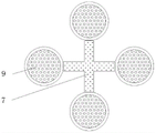
图3为本发明转架与滤网连接结构示意图;3 is a schematic diagram of the connection structure between the turn frame and the filter screen of the present invention;
图4为本发明连接架、喷水通道、电热板和杀菌灯板连接结构示意图;4 is a schematic diagram of the connection structure of the connecting frame, the water spray channel, the electric heating plate and the germicidal lamp plate of the present invention;
图5为本发明杀菌箱、杀菌灯管和搅拌柱连接结构示意图;5 is a schematic diagram of the connection structure of the sterilization box, the sterilization lamp tube and the stirring column of the present invention;
图6为本发明第一连接管道与离心净乳机构连接结构示意图;6 is a schematic diagram of the connection structure between the first connecting pipe of the present invention and the centrifugal milk cleaning mechanism;
图7为本发明离心净乳箱、限位板和滚珠连接结构示意图。FIG. 7 is a schematic diagram of the connection structure of the centrifugal clean milk box, the limit plate and the balls of the present invention.
图中:1、承载台,2、自锁滚轮,3、储水槽,4、电动排水阀,5、支架,6、第一马达,7、转架,8、第二马达,9、滤网,10、开口,11、承载箱,12、进料通道,13、第一液泵,14、第一连接管道,15、离心净乳机构,1501、离心净乳箱,1502、电动进水阀,1503、第一电动伸缩柱,1504、刮环,1505、限位板,1506、滚珠,1507、滤筒,1508、齿条,1509、第三马达,1510、锥齿轮传动,1511、齿轮,1512、电动排料阀,1513、底塞,1514、第二连接管道,16、自清洁机构,1601、承载架,1602、第二电动伸缩柱,1603、连接架,1604、喷水通道,1605、电热板,1606、杀菌灯板,17、输料管道,18、第二液泵,19、杀菌箱,20、杀菌灯管,21、第四马达,22、搅拌柱,23、电动出料阀。In the picture: 1. Loading table, 2. Self-locking roller, 3. Water storage tank, 4. Electric drain valve, 5. Bracket, 6. First motor, 7. Turn frame, 8. Second motor, 9. Filter screen , 10, opening, 11, carrying box, 12, feeding channel, 13, first liquid pump, 14, first connecting pipe, 15, centrifugal milk cleaning mechanism, 1501, centrifugal milk cleaning box, 1502, electric water inlet valve , 1503, first electric telescopic column, 1504, scraper ring, 1505, limit plate, 1506, ball, 1507, filter cartridge, 1508, rack, 1509, third motor, 1510, bevel gear drive, 1511, gear, 1512, electric discharge valve, 1513, bottom plug, 1514, second connecting pipe, 16, self-cleaning mechanism, 1601, carrying frame, 1602, second electric telescopic column, 1603, connecting frame, 1604, water spray channel, 1605 , electric heating plate, 1606, germicidal lamp board, 17, conveying pipeline, 18, second liquid pump, 19, sterilization box, 20, germicidal lamp tube, 21, fourth motor, 22, stirring column, 23, electric discharge valve.
具体实施方式Detailed ways
下面将结合本发明实施例中的附图,对本发明实施例中的技术方案进行清楚、完整地描述,显然,所描述的实施例仅仅是本发明一部分实施例,而不是全部的实施例。基于本发明中的实施例,本领域普通技术人员在没有做出创造性劳动前提下所获得的所有其他实施例,都属于本发明保护的范围。The technical solutions in the embodiments of the present invention will be clearly and completely described below with reference to the accompanying drawings in the embodiments of the present invention. Obviously, the described embodiments are only a part of the embodiments of the present invention, but not all of the embodiments. Based on the embodiments of the present invention, all other embodiments obtained by those of ordinary skill in the art without creative efforts shall fall within the protection scope of the present invention.
请参阅图1-7,本发明提供一种技术方案:一种具有预粉碎结构的辊压机,根据图1和图2所示,电动排水阀4贯穿承载台1的下端面与储水槽3相贯通,且储水槽3开设在承载台1的一侧内,同时承载台1的底部固定有自锁滚轮2,承载台1上端面的一侧固定有支架5,且支架5的顶部转动连接有转架7,同时转架7的外侧转动连接有滤网9,支架5的顶部内固定有第一马达6,且第一马达6的顶部与转架7相连接,转架7可在第一马达6的作用下转动,从而带动四个滤网9转动,方便轮流使用四个滤网9,转架7的外端内固定有第二马达8,且第二马达8的输出端与滤网9相连接,使用后的滤网9可在喷水通道1604、电热板1605和杀菌灯板1606的作用下依次得到清洗、烘干和杀菌处理,在此过程中,滤网9可在第二马达8的作用下转动,方便得到全面的清洗、烘干和杀菌处理,滤网9设置有四个,且最右侧滤网9贯穿开口10,同时开口10对称开设在承载箱11的两侧,轮流使用四个滤网9可使整个操作更加有序高效。Please refer to FIGS. 1-7 , the present invention provides a technical solution: a roller press with a pre-crushing structure. As shown in FIGS. 1 and 2 , the
根据图1、图2和图3所示,承载箱11固定在承载台1上端面的一侧,且承载箱11的顶部固定有进料通道12,承载箱11的内底部固定有第一液泵13,且第一液泵13的一侧固定有第一连接管道14。As shown in FIGS. 1 , 2 and 3 , the
根据图1、图2和图4所示,离心净乳机构15固定在承载台1上端面的中间处,且离心净乳机构15与第一连接管道14的末端相连接,离心净乳机构15包括离心净乳箱1501、电动进水阀1502、第一电动伸缩柱1503、刮环1504、限位板1505、滚珠1506、滤筒1507、齿条1508、第三马达1509、锥齿轮传动1510、齿轮1511、电动排料阀1512、底塞1513和第二连接管道1514,且离心净乳箱1501固定在承载台1上端面的中间处,同时离心净乳箱1501的顶部固定有电动进水阀1502,离心净乳箱1501顶部两侧对称固定有第一电动伸缩柱1503,且第一电动伸缩柱1503贯穿离心净乳箱1501顶部与刮环1504相连接,滤筒1507的上下两侧均转动连接在限位板1505之间,且限位板1505固定在离心净乳箱1501的内壁上,得到初步除杂处理后的原料乳进入离心净乳箱1501内之后,滤筒1507可对原料乳进行更加细微彻底的过滤除杂处理,同时滤筒1507可高速旋转,方便对原料乳进行离心除杂处理,此时得到过滤处理后的原料乳穿过滤筒1507流到离心净乳箱1501的内底部并通过第二连接管道1514排走,杂质则残留在滤筒1507内,除杂工作结束后可拧下底塞1513并打开电动排料阀1512排掉滤筒1507内的杂质,同时刮环1504可在第一电动伸缩柱1503的伸长作用下紧贴着滤筒1507的内壁向下移动,使滤筒1507内杂质的刮除效果更加彻底,关上电动排料阀1512并打开电动进水阀1502后可向滤筒1507内通水,方便对滤筒1507内部进行清洗,同时刮环1504可反复上下移动,使清洗效果更加彻底,最后可打开电动排料阀1512排出使用后的清洗水,限位板1505设置有两组,且每组限位板1505由上下两部分组成,同时每组下半部分限位板1505的上端面卡合连接有滚珠1506,滤筒1507在高速旋转的过程中,滚珠1506滚动,方便减小滤筒1507与限位板1505之间的摩擦,使滤筒1507旋转起来更加顺滑,第三马达1509固定在离心净乳箱1501的一侧,且第三马达1509的输出端与锥齿轮传动1510相连接,同时锥齿轮传动1510的顶部与齿轮1511相连接,齿轮1511啮合连接在齿条1508上,且齿条1508固定在滤筒1507的外表面上,同时滤筒1507的底部固定有电动排料阀1512,离心净乳箱1501的底部螺纹连接有底塞1513,且离心净乳箱1501的另一侧固定有第二连接管道1514,同时第二连接管道1514的末端与输料管道17相连接,锥齿轮传动1510可在第三马达1509的作用下转动,从而带动齿轮1511转动,齿轮1511与齿条1508啮合连接在一起,滤筒1507高速旋转,方便对有原料乳进行离心除杂处理。As shown in FIGS. 1 , 2 and 4 , the centrifugal
根据图1、图2和图5所示,自清洁机构16包括承载架1601、第二电动伸缩柱1602、连接架1603、喷水通道1604、电热板1605和杀菌灯板1606,且承载架1601固定在承载台1上,承载架1601内顶部的下侧通过第二电动伸缩柱1602与连接架1603相连接,且连接架1603的三端分别与喷水通道1604、电热板1605和杀菌灯板1606相连接,连接架1603通过第二电动伸缩柱1602与承载架1601构成伸缩结构,连接架1603可在第二电动伸缩柱1602的伸缩作用下上下移动,使喷水通道1604、电热板1605和杀菌灯板1606能够紧靠滤网9完成清洗、烘干和杀菌操作,且不会影响滤网9翻转。As shown in FIGS. 1 , 2 and 5 , the self-cleaning
根据图1、图2、图6和图7所示,输料管道17与离心净乳机构15的末端相连接,且输料管道17的首端固定有第二液泵18,同时输料管道17的末端与杀菌箱19相连接,杀菌箱19固定在承载台1上端面的另一侧,且杀菌箱19的内壁上固定有杀菌灯管20,杀菌箱19的内底部转动连接有搅拌柱22,且杀菌箱19的一侧固定有电动出料阀23,杀菌箱19的底部内固定有第四马达21,且第四马达21的顶部与搅拌柱22相连接,得到彻底除杂后的原料乳进入杀菌箱19内并在杀菌灯管20的作用下得到杀菌处理的过程中,搅拌柱22可在第四马达21的作用下转动,方便对原料乳进行搅拌处理,使原料乳能够得到全面彻底的杀菌处理。As shown in Figures 1, 2, 6 and 7, the
工作原理:在使用该具有自清洁功能的离心净乳装置时,首先利用自锁滚轮将该装置移动至所需地点,接着向进料通道12内通料,原料乳落到对应的滤网9内之后可在滤网9的作用下得到过滤处理,此时杂质残留在滤网9上,启动第一液泵13后,过滤后的乳通过第一连接管道14进入到离心净乳箱1501内后,滤筒1507对原料乳进行更加细微彻底的过滤除杂处理,同时启动第三马达1509,第三马达1509带动锥齿轮传动1510转动,从而带动齿轮1511转动,齿轮1511与齿条1508啮合连接在一起,滤筒1507高速旋转,以此对有原料乳进行离心除杂处理,滚珠1506可辅助滤筒1507旋转,此时得到过滤处理后的原料乳穿过滤筒1507流到离心净乳箱1501的内底部,杂质则残留在滤筒1507内,启动第一马达6后,第一马达6带动转架7逆时针旋转45度,此时粘有杂质的滤网9到达喷水通道1604的正下方,滤网9在对应第二马达8的作用下旋转180度之后,启动第二电动伸缩柱1602,第二电动伸缩柱1602伸长,喷水通道1604随着连接架1603一起向下移动并紧靠滤网9向下喷水,方便冲掉滤网9上的杂质,承载台1的上端面开设有通孔,且通孔与储水槽3相贯通,杂质随着水流一起穿过通孔流到储水槽3内,打开电动排水阀4之后可排出储水槽3内的杂质和水,清除完滤网9上的杂质之后,转架7继续逆时针旋旋转45度,启动电热板1605可烘干滤网9,随后转架7继续逆时针旋旋转45度,打开杀菌灯板1606可对滤网9进行杀菌消毒处理,在烘干杀菌的过程中,滤网9可360度转动,同时连接架1603可上下移动,方便紧靠滤网9完成全面的烘干以及杀菌消毒处理,转架7继续逆时针旋旋转45度之后,得到清洁处理后的滤网9可穿过开口10进入到平承载箱11内,滤网9设置有四个,可轮流使用,原料乳在离心净乳箱1501的作用下得到除杂处理之后,启动第二液泵18,原料乳先后经过第二连接管道1514和输料管道17进入杀菌箱19内,启动杀菌灯管20、第四马达21后,杀菌灯管20对原料乳进行杀菌消毒处理,第四马达21带动搅拌柱22转动,以此对原料乳进行搅拌处理,使原料乳得到全面彻底的杀菌处理,打开电动出料阀23后可排出原料乳,使用完该装置之后可拧下底塞1513并打开电动排料阀1512排掉滤筒1507内的杂质,同时启动第一电动伸缩柱1503,第一电动伸缩柱1503伸长,刮环1504紧贴着滤筒1507的内壁向下移动,使滤筒1507内杂质的刮除效果更加彻底,关上电动排料阀1512并打开电动进水阀1502后可向滤筒1507内通水,以此对滤筒1507内部进行清洗,同时刮环1504上下反复移动,使清洗效果更加彻底,随后可打开电动排料阀1512排出使用后的清洗水,这就完成整个工作,且本说明书中未作详细描述的内容属于本领域专业技术人员公知的现有技术。Working principle: When using the centrifugal milk cleaning device with self-cleaning function, firstly use the self-locking roller to move the device to the desired location, then feed the material into the feeding
术语“中心”、“纵向”、“横向”、“前”、“后”、“左”、“右”、“竖直”、“水平”、“顶”、“底”、“内”、“外”等指示的方位或位置关系为基于附图所示的方位或位置关系,仅是为便于描述本发明的简化描述,而不是指示或暗指所指的装置或元件必须具有特定的方位、为特定的方位构造和操作,因而不能理解为对本发明保护内容的限制。The terms "center", "portrait", "horizontal", "front", "rear", "left", "right", "vertical", "horizontal", "top", "bottom", "inner", The orientation or positional relationship indicated by "outside" is based on the orientation or positional relationship shown in the accompanying drawings, and is only a simplified description for the convenience of describing the present invention, rather than indicating or implying that the indicated device or element must have a specific orientation , are constructed and operated in a specific orientation, and therefore should not be construed as limiting the protection content of the present invention.
尽管参照前述实施例对本发明进行了详细的说明,对于本领域的技术人员来说,其依然可以对前述各实施例所记载的技术方案进行修改,或者对其中部分技术特征进行等同替换,凡在本发明的精神和原则之内,所作的任何修改、等同替换、改进等,均应包含在本发明的保护范围之内。Although the present invention has been described in detail with reference to the foregoing embodiments, for those skilled in the art, it is still possible to modify the technical solutions described in the foregoing embodiments, or to perform equivalent replacements for some of the technical features. Any modification, equivalent replacement, improvement, etc. made within the spirit and principle of the present invention shall be included within the protection scope of the present invention.
Claims (9)
Priority Applications (1)
| Application Number | Priority Date | Filing Date | Title |
|---|---|---|---|
| CN202210202570.3A CN114570533A (en) | 2022-03-03 | 2022-03-03 | Centrifugal milk purifying device with self-cleaning function |
Applications Claiming Priority (1)
| Application Number | Priority Date | Filing Date | Title |
|---|---|---|---|
| CN202210202570.3A CN114570533A (en) | 2022-03-03 | 2022-03-03 | Centrifugal milk purifying device with self-cleaning function |
Publications (1)
| Publication Number | Publication Date |
|---|---|
| CN114570533A true CN114570533A (en) | 2022-06-03 |
Family
ID=81775903
Family Applications (1)
| Application Number | Title | Priority Date | Filing Date |
|---|---|---|---|
| CN202210202570.3A Withdrawn CN114570533A (en) | 2022-03-03 | 2022-03-03 | Centrifugal milk purifying device with self-cleaning function |
Country Status (1)
| Country | Link |
|---|---|
| CN (1) | CN114570533A (en) |
Cited By (1)
| Publication number | Priority date | Publication date | Assignee | Title |
|---|---|---|---|---|
| CN116716699A (en) * | 2023-06-15 | 2023-09-08 | 盐城神力制绳有限公司 | A warp and weft knitting machine with noise reduction structure |
-
2022
- 2022-03-03 CN CN202210202570.3A patent/CN114570533A/en not_active Withdrawn
Cited By (1)
| Publication number | Priority date | Publication date | Assignee | Title |
|---|---|---|---|---|
| CN116716699A (en) * | 2023-06-15 | 2023-09-08 | 盐城神力制绳有限公司 | A warp and weft knitting machine with noise reduction structure |
Similar Documents
| Publication | Publication Date | Title |
|---|---|---|
| CN208949000U (en) | A kind of environment-friendly sewage processing unit | |
| CN217854879U (en) | Filter equipment is used in production of medical liquid dressing | |
| CN118527442A (en) | Beverage bottle cleaning equipment for beverage production | |
| CN221788451U (en) | Efficient and intelligent sewage treatment device | |
| CN214257912U (en) | Device for cleaning betel nut seeds | |
| CN114538559A (en) | An environmentally friendly water treatment cycle purification device | |
| CN213803164U (en) | Filter equipment for chemical production | |
| CN220589101U (en) | Sterilizing algicide liquid medicine filtering device | |
| CN221084998U (en) | Environment-friendly dust filter | |
| CN219091396U (en) | Sand washing equipment for MBF active sand filter | |
| CN209791058U (en) | High-efficient decoloration filter equipment of oil environmental protection | |
| CN219462733U (en) | Rotary sewage slag remover | |
| CN216062188U (en) | Water storage tank for water treatment | |
| CN217378388U (en) | Paper pulp filtration equipment | |
| CN214990739U (en) | Softened water treatment device for large boiler | |
| CN219091295U (en) | Anti-blocking filtering device for water purification filtration | |
| CN210550470U (en) | Processing apparatus of cutting fluid | |
| CN222923106U (en) | Beer production equipment with multi-stage filtration function | |
| CN222752705U (en) | A sewage treatment filtering device | |
| CN211914763U (en) | Can prevent belt cleaning device for digestion endoscope that waste liquid pollutes | |
| CN209188347U (en) | A kind of independent recovery system for fermentation tail gas | |
| CN222677346U (en) | Glass etching liquid circulating device | |
| CN223175972U (en) | Integrated sewage treatment equipment | |
| CN221739928U (en) | Deionized water purifying equipment | |
| CN219186066U (en) | Filter equipment is used in circulating water aquaculture |
Legal Events
| Date | Code | Title | Description |
|---|---|---|---|
| PB01 | Publication | ||
| PB01 | Publication | ||
| SE01 | Entry into force of request for substantive examination | ||
| SE01 | Entry into force of request for substantive examination | ||
| WW01 | Invention patent application withdrawn after publication |
Application publication date: 20220603 |
|
| WW01 | Invention patent application withdrawn after publication |