Disclosure of Invention
The invention aims to provide an ammeter detection device, which can realize quick and automatic detection of an internal circuit of an ammeter, can realize batch detection and has high efficiency.
In order to solve the technical problem, the invention provides an ammeter detection device, which comprises a supporting mechanism, a rotating mechanism, a plurality of mounting mechanisms, a detection mechanism and a driving mechanism, wherein the rotating mechanism is rotationally connected with the supporting mechanism through a rotating shaft; the installation mechanisms are respectively arranged on the peripheral wall of the rotating mechanism and used for placing an ammeter; the detection mechanism is arranged on the supporting mechanism and is positioned at the top of the rotating mechanism; the driving mechanism is arranged on the supporting mechanism and is connected with the rotating mechanism;
wherein, actuating mechanism drive slewing mechanism rotates, slewing mechanism drives installation mechanism passes through one by one detection mechanism, detection mechanism is right installation mechanism's ammeter detects and/or marks.
Preferably, the supporting mechanism comprises a supporting bottom plate and two supporting side plates, the rotating mechanism is located between the two supporting side plates, and the rotating mechanism is rotatably connected with the supporting side plates through a rotating shaft.
Preferably, the support bottom plate is provided with a discharge port, and the discharge port is arranged corresponding to the rotating mechanism.
Preferably, the rotating mechanism is of a cylindrical structure, and the rotating mechanism is provided with a plurality of mounting grooves corresponding to the mounting mechanism.
Preferably, the mounting mechanism comprises two oppositely arranged clamping units, each clamping unit comprises a clamping plate, a buffer plate and a pushing column; wherein,
one end of the pushing column is of a spherical structure and is abutted against the supporting side plate after sliding through the rotating mechanism;
the buffer plate is connected with the other end of the pushing column, a sliding cavity is arranged inside the buffer plate, and a buffer spring is arranged in the sliding cavity;
the clamping plate is provided with a sliding rod, one end of the sliding rod is inserted in the sliding cavity in a sliding mode, and the sliding rod is connected with the buffer spring;
and the bottom of the supporting side plate is provided with an emptying groove corresponding to the pushing column.
Preferably, the rotating mechanism is provided with a discharge groove corresponding to the mounting groove and a slideway perpendicular to the support side plate, and the slideway is communicated with the mounting groove and the discharge groove; the bottom surface of the mounting groove is provided with a connecting hole communicated with the discharge groove; the mounting mechanism further comprises a discharge bottom plate, a discharge shaft, a discharge limit member and a discharge spring; wherein,
the discharge bottom plate is arranged in the mounting groove;
one end of the discharge shaft is connected with the discharge bottom plate, and the other end of the discharge shaft penetrates through the connecting hole and enters the discharge groove;
the two discharge limiting parts are arranged oppositely; each discharge limiting part comprises a limiting frame, a limiting rack and a return spring, the limiting frame is slidably arranged on the slide way, one end of the limiting frame is connected with the buffer plate, and the other end of the limiting frame is connected with the limiting rack; the limiting racks are arranged in the discharge groove, and the two limiting racks clamp the discharge shaft; one end of the reset spring is connected with the limiting frame, and the other end of the reset spring is connected with the side wall of the slide way; when the clamping unit clamps the ammeter, the two buffer plates are close to each other to drive the two limiting racks to clamp the discharge shaft, when the clamping unit moves to the position of the emptying groove, the two buffer plates are far away from each other, the reset spring pushes the limiting frame to move towards the direction of the supporting side plate, and the two limiting racks loosen the discharge shaft;
the discharge spring is sleeved on the discharge shaft, one end of the discharge spring is connected with the bottom surface of the discharge bottom plate, and the other end of the discharge spring is connected with the side wall of the connecting hole.
Preferably, each limit rack is provided with a first tooth; one end of the discharge shaft is provided with a limiting sliding hole; two ends of the limiting sliding hole are respectively provided with a limiting block which can slide along the limiting sliding hole, and the limiting block is provided with a second engaging tooth matched with the first engaging tooth; and a connecting spring is arranged in the limiting sliding hole, and two ends of the connecting spring are respectively connected with the two limiting blocks.
Preferably, the discharge bottom plate is provided with a positioning column.
Preferably, two sides of the rotating mechanism are provided with an electrifying sliding groove; the detection mechanism comprises a marking unit, a control unit and two electrifying units; wherein,
the marking unit is arranged on the supporting bottom plate, and one end of the marking unit is positioned right above the rotating mechanism;
the electrifying units are arranged in one-to-one correspondence with the supporting side plates, and each electrifying unit comprises an electrifying column, an electrifying ball, a connecting wire, an electrifying terminal and a supporting spring; the power-on column is arranged at the top of the supporting side plate, and the power-on ball is slidably arranged in the power-on sliding groove; one end of the connecting wire is connected with the electrifying ball; the power-on terminal is arranged in the mounting groove and is connected with the other end of the connecting wire; the supporting spring is arranged on the electrifying chute, one end of the supporting spring is connected with the electrifying ball, and the other end of the supporting spring is connected with the inner wall of the electrifying chute;
and the control unit is electrically connected with the marking unit and the electrifying column respectively.
Preferably, the driving mechanism comprises a driving plate, a driving slider, a driving rod, a swinging rod, a transmission unit, a turning rod and a supporting rod; wherein,
the driving plate is provided with a cross sliding chute which comprises a vertical sliding chute and a horizontal sliding chute which are intersected; the driving plate is connected with a rotating shaft of the rotating mechanism;
the driving sliding block is slidably arranged on the cross sliding groove;
one end of the driving rod is rotatably connected with the driving slide block;
one end of the swinging rod is rotatably connected with the other end of the driving rod;
the transmission unit is arranged on the supporting mechanism, is connected with the other end of the swinging rod and is used for driving the swinging rod to swing;
one end of the turning rod is rotatably connected with the middle part of the driving rod;
the support rod is arranged on the support mechanism and is rotatably connected with the other end of the turning rod.
The invention has the following beneficial effects:
the invention is provided with a rotating mechanism, a plurality of mounting mechanisms are arranged on the rotating mechanism, the rotating mechanism is driven to rotate by a driving mechanism, the mounting mechanisms are further driven to sequentially pass through a detection mechanism, and the detection mechanism detects and marks an ammeter in the mounting mechanisms; the whole process is simple and quick, automatic detection can be realized only by placing the ammeter in the installation mechanism, and the detection efficiency is high.
Detailed Description
The technical solutions in the embodiments of the present application will be clearly and completely described below with reference to the drawings in the embodiments of the present application, and it is obvious that the described embodiments are only a part of the embodiments of the present application, and not all of the embodiments. All other embodiments, which can be derived by a person skilled in the art from the embodiments given herein without making any creative effort, shall fall within the protection scope of the present application.
In the description of the present application, it is to be understood that the terms "center", "upper", "lower", "front", "rear", "left", "right", "vertical", "horizontal", "top", "bottom", "inner", "outer", and the like indicate orientations or positional relationships based on those shown in the drawings, and are only for convenience in describing the present application and simplifying the description, but do not indicate or imply that the referred device or element must have a particular orientation, be constructed in a particular orientation, and be operated, and thus should not be construed as limiting the present application.
In the description of the present application, it is to be noted that, unless otherwise explicitly specified or limited, the terms "mounted," "connected," and "connected" are to be construed broadly, e.g., as meaning either a fixed connection, a removable connection, or an integral connection; can be mechanically or electrically connected; they may be connected directly or indirectly through intervening media, or they may be interconnected between two elements. The specific meaning of the above terms in this application will be understood to be a specific case for those of ordinary skill in the art.
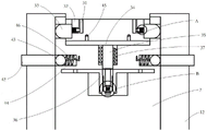
Referring to fig. 1, a preferred embodiment of the present invention provides an electricity meter detection device, which includes a support mechanism 1, a rotation mechanism 2, a plurality of mounting mechanisms 3, a detection mechanism 4 and a driving mechanism 5, wherein the rotation mechanism 2 is rotatably connected to the support mechanism 1 through a rotation shaft; the mounting mechanisms 3 are respectively arranged on the peripheral wall of the rotating mechanism 2, and the mounting mechanisms 3 are used for mounting an ammeter; the detection mechanism 4 is arranged on the support mechanism 1 and is positioned at the top of the rotating mechanism 2; the driving mechanism 5 is arranged on the supporting mechanism 1 and is connected with the rotating mechanism 2;
wherein, actuating mechanism 5 drive slewing mechanism 2 rotates, and slewing mechanism 2 drives installation mechanism 3 and passes through detection mechanism 4 one by one, and detection mechanism 4 detects and/or marks the ammeter of installation mechanism 3.
When the ammeter detection device is used, an ammeter is installed in the installation mechanism 3, the driving mechanism 5 drives the rotating mechanism 2 to rotate, the rotating mechanism 2 drives the installation mechanism 3 to rotate, the installation mechanism 3 passes through the detection mechanism 4 on the top one by one, the detection mechanism 4 detects the ammeter in the installation mechanism 3, qualified ammeters are detected, and the detection mechanism 4 marks the ammeter; after the detected electric meter is rotated to a certain position, the electric meter automatically falls down through gravity or is manually taken out.
In some preferred embodiments of the present invention, the supporting mechanism 1 includes a supporting bottom plate 11 and two supporting side plates 12, the rotating mechanism 2 is located between the two supporting side plates 12, and the rotating mechanism 2 is rotatably connected to the supporting side plates 12 through a rotating shaft.
In some preferred embodiments of the present invention, the supporting bottom plate 11 is provided with a discharge port 13, and the discharge port 13 is disposed corresponding to the rotating mechanism 2. Thus, when the mounting mechanism 3 rotates to the bottom position of the rotating mechanism 2, the ammeter falls off and falls into the discharge port 13 due to the self gravity, and subsequent transportation and recovery are facilitated.
In some preferred embodiments of the present invention, the rotating mechanism 2 is a cylindrical structure, and the rotating mechanism 2 is provided with a plurality of mounting slots corresponding to the mounting mechanism 3.
Referring to fig. 2-6, in some preferred embodiments of the present invention, the mounting mechanism 3 comprises two oppositely disposed clamping units, each of which comprises a clamping plate 31, a buffer plate 32 and a pushing column 33; wherein,
one end of the pushing column 33 is a spherical structure, and the pushing column slides through the rotating mechanism 2 and then abuts against the supporting side plate 12;
the buffer plate 32 is connected with the other end of the pushing column 33, a sliding cavity 321 is arranged inside the buffer plate 32, and a buffer spring 322 is arranged in the sliding cavity 321;
the clamping plate 31 is provided with a sliding rod 311, one end of the sliding rod 311 is slidably inserted into the sliding cavity 321, and is connected with the buffer spring 322;
the bottom of the supporting side plate 12 is provided with an emptying groove 14 corresponding to the pushing column 33.
Specifically, when the electric meter is placed in the mounting mechanism 3, one end of the pushing column 33 abuts against the supporting side plate 12, the other end of the pushing column pushes the buffer plate 32 to move, the buffer plate 32 pushes the buffer spring 322, the buffer spring 322 pushes the sliding rod 311, the sliding rod 311 pushes the clamping plates 31, the two clamping plates 31 are close to each other, and therefore the electric meter is clamped; when one of the mounting mechanisms 3 is turned to the bottom of the support side plate 12, one end of the push rod 33 enters the emptying groove 14, and then the electric meter is released by the clamping unit, so that the electric meter drops due to its own weight.
It should be noted that, when placing the ammeter in installation mechanism 3, the ammeter both ends can support and press grip block 31, and grip block 31 can compress buffer spring 322, and then has sufficient space to put into for the ammeter, waits that the ammeter is put into the back that finishes, and buffer spring 322 gives grip block 31 thrust all the time, and then makes grip block 31 centre gripping ammeter all the time. Promote post 33 and make for the elastic material moreover, have certain elasticity performance, when receiving the extrusion, can produce certain deformation, consequently receive the ammeter extrusion at grip block 31 time, promote post 33 and can produce slight deformation, and then make the outside displacement that takes place of buffer board 32, and then make the ammeter have sufficient space to put into.
Referring to fig. 2 to 6, in some preferred embodiments of the present invention, the rotating mechanism is provided with a discharge slot corresponding to the mounting slot and a chute perpendicular to the support side plate 12, the chute communicating the mounting slot and the discharge slot; the bottom surface of the mounting groove is provided with a connecting hole communicated with the discharge groove; the mounting mechanism 3 further includes a discharge base plate 34, a discharge shaft 35, a discharge stopper 36, and a discharge spring 37; wherein,
the discharge bottom plate 34 is arranged in the mounting groove;
one end of the discharge shaft 35 is connected to the discharge base plate 34, and the other end thereof passes through the connection hole to enter the discharge groove;
two discharge stoppers 36 are provided and arranged oppositely; each discharge limiting member 36 comprises a limiting frame 361, a limiting rack 362 and a return spring 363, wherein the limiting frame 361 is slidably arranged on the slide way, one end of the limiting frame 361 is connected with the buffer plate 32, and the other end of the limiting frame 361 is connected with the limiting rack 362; the limit racks 362 are arranged in the discharge groove, and the two limit racks 362 clamp the discharge shaft 35; one end of the return spring 363 is connected with the limiting frame 361, and the other end of the return spring 363 is connected with the side wall of the slide way; when the clamping unit clamps the ammeter, the two buffer plates 32 approach to each other to drive the two limiting racks 362 to clamp the discharging shaft 35, when the clamping unit moves to the position of the emptying groove 14, the two buffer plates 32 are away from each other, the reset spring 363 pushes the limiting frame 361 to move towards the direction of the supporting side plate 12, and the two limiting racks 362 loosen the discharging shaft 35;
the discharge spring 37 is fitted around the discharge shaft 35, and has one end connected to the bottom surface of the discharge bottom plate 34 and the other end connected to the side wall of the hole.
Specifically, when the ammeter is mounted on the mounting mechanism 3, the ammeter is respectively extruded towards the bottom surface and two sides of the mounting groove, the ammeter pushes the clamping plates 31 towards two sides, the clamping plates 31 push the buffer plates 32 to move towards the direction away from the rotating mechanism 2, the buffer plates 32 drive the limiting racks 361 to slide in the slide ways, and the limiting racks 361 drive the limiting racks 362 to move outwards, so that the discharging shaft 35 is loosened; meanwhile, the electricity meter also pushes the discharge bottom plate 34, the discharge bottom plate 34 pushes the discharge shaft 35, and the discharge shaft 35 moves downwards; after the ammeter is installed, the buffer plate 32 and the clamping plate 31 move towards the direction of the ammeter to clamp the ammeter, and then the limiting rack 362 is driven to clamp the discharging shaft 35 again; when the ammeter is detected and turned to the bottom of the supporting side plate 12, the pushing column 33 slides into the emptying groove 14, the clamping plates 31 are separated from each other, the ammeter is loosened, the reset spring 363 pushes the limiting frame 361, the limiting frame 361 drives the limiting rack 362 to loosen the discharging shaft 35, and the discharging bottom plate 34 is pushed outwards under the action of the discharging spring 37 to push the ammeter out of the mounting mechanism 3.
Referring to fig. 5, in some preferred embodiments of the present invention, each of the limit racks 362 is provided with a first tooth; one end of the discharge shaft 35 is provided with a limiting slide hole 351; two ends of the limiting slide hole 351 are respectively provided with a limiting block 352 capable of sliding along the limiting slide hole, and the limiting block 352 is provided with a second engaging tooth matched with the first engaging tooth; the inside of spacing slide opening 351 is provided with connecting spring 353, and two stopper 352 are connected respectively to the both ends of connecting spring 353. In this way, the stopper rack 362 can more stably clamp the discharge shaft 35 by the cooperation of the first and second engaging teeth.
In some preferred embodiments of the invention, the discharge floor 34 is provided with positioning posts.
Referring to fig. 2 to 6, in some preferred embodiments of the present invention, two sides of the rotating mechanism 2 are provided with an electrifying chute; the detection mechanism 4 includes a marking unit 41, a control unit, and two energizing units; wherein,
the marking unit 41 is arranged on the support base plate 11, and one end of the marking unit is positioned right above the rotating mechanism 2;
the energizing units are arranged in one-to-one correspondence with the support side plates 12, and each energizing unit comprises an energizing post 42, an energizing ball 43, a connecting wire 44, an energizing terminal 45 and a support spring 46; the power-on column 42 is arranged on the top of the support side plate 12, and the power-on ball 43 is slidably arranged in the power-on chute; one end of the connecting wire 44 is connected with the electrifying ball 43; the power-on terminal 45 is arranged in the mounting groove and is connected with the other end of the connecting wire 44; the supporting spring 46 is arranged on the electrifying chute, one end of the supporting spring is connected with the electrifying ball 43, and the other end of the supporting spring is connected with the inner wall of the electrifying chute;
and the control unit is electrically connected with the marking unit 41 and the electrifying column 42 respectively.
Specifically, when the electric meter is installed in the installation groove, the detection port of the electric meter is aligned with the power-on terminal 45 and inserted; when the mounting mechanism 3 moves to the top of the supporting side plate 12, the control unit controls the marking unit 41 to mark the qualified ammeter, wherein the control unit is used for electrifying one of the electrifying columns 42, the electrifying ball 43 is abutted to the electrified electrifying column 42, if the internal circuit of the ammeter is normally communicated, the other electrifying column 42 is also electrified, and the ammeter is qualified. The support spring 46 always pushes the electrified ball 43, so that the electrified ball 43 is always attached to the support side plate 12, and the electrified ball 43 can be abutted together when passing through the electrified post 42.
It should be noted that the control unit itself includes a power supply; the marking unit 41 is an existing marking unit 41, and is mainly used for marking qualified ammeters to facilitate subsequent screening and identification.
Referring to fig. 7, in some preferred embodiments of the present invention, the driving mechanism 5 includes a driving plate 51, a driving slider, a driving lever 52, a swinging lever 53, a transmission unit 54, a direction-changing lever 55, and a supporting lever 56; wherein,
the driving plate 51 is provided with a cross-shaped sliding chute which comprises a vertical sliding chute and a horizontal sliding chute which are intersected; the driving plate 51 is connected with a rotating shaft of the rotating mechanism 2;
the driving slide block is arranged on the cross sliding chute in a sliding way;
one end of the driving rod 52 is rotatably connected with the driving slider;
one end of the swing lever 53 is rotatably connected to the other end of the drive lever 52;
the transmission unit 54 is disposed on the support mechanism 1, connected to the other end of the swing lever 53, and configured to drive the swing lever 53 to swing;
one end of the direction changing rod 55 is rotatably connected with the middle part of the driving rod 52;
the support rod 56 is disposed on the support mechanism 1, and is rotatably connected to the other end of the direction-changing rod 55.
Specifically, when the transmission unit 54 drives the swing rod 53 to swing in one direction, the driving rod 52 drives the driving slider to move downward in the vertical chute, and further drives the rotating mechanism 2 to rotate in one direction; when the driving slide block slides to the middle position of the cross groove, due to the limitation of the turning rod 55, the driving slide block can slide into the adjacent horizontal sliding groove, at the moment, the transmission unit 54 stops for a certain time for the detection mechanism 4 to detect the electricity meter, after a certain time, the transmission unit 54 controls the swinging rod 53 to swing in the opposite direction, the driving rod 52 drives the driving slide block to slide upwards, the driving slide block pushes the horizontal sliding groove, the driving plate 51 rotates, the rotating mechanism 2 is further driven to rotate in the original direction, and the process is repeated until the horizontal sliding groove becomes the vertical sliding groove.
In some preferred embodiments of the present invention, the transmission unit 54 includes a driving motor 541, a driving wheel 542, a transmission belt 543, and a driven wheel 544, the driving motor 541 is disposed on the supporting mechanism 1, an output shaft of the driving motor 541 is connected with the driving wheel 542, the driven wheel 544 is disposed on the supporting mechanism 1, and the transmission belt 543 connects the driving wheel 542 and the driven wheel 544. In this way, the driving motor 541 drives the driving pulley 542 to rotate, the driving pulley 542 drives the driven pulley 544 to rotate through the driving belt 543, and the driven pulley 544 drives the swing lever 53 to rotate. The oscillating lever 53 can be controlled to oscillate repeatedly by controlling the forward and reverse rotation of the driving motor 541.
In some preferred embodiments of the present invention, the direction-changing rod 55 is detachably connected to the driving rod 52, and the driving mechanism 5 includes a pulling-up pin 57, and the pulling-up pin 57 is disposed on the direction-changing rod 55. The direction change lever 55 is separated from the drive lever 52 by pulling up the pulling-up pin 57 in a direction away from the rotation mechanism, so that the rotation mechanism 2 stops rotating.
To sum up, a preferred embodiment of the present invention provides an electricity meter detecting device, which is compared with the prior art:
the invention is provided with a rotating mechanism 2, a plurality of mounting mechanisms 3 are arranged on the rotating mechanism 2, the rotating mechanism 2 is driven to rotate by a driving mechanism 5, and further the mounting mechanisms 3 are driven to pass through a detection mechanism 4 successively, and the detection mechanism 4 detects and marks the electric meters in the mounting mechanisms 3; the whole process is simple and quick, automatic detection can be realized only by placing the ammeter in the installation mechanism 3, and the detection efficiency is high.
The above description is only a preferred embodiment of the present invention, and it should be noted that, for those skilled in the art, various modifications and substitutions can be made without departing from the technical principle of the present invention, and these modifications and substitutions should also be regarded as the protection scope of the present invention.