Disclosure of Invention
Problems to be solved by the invention
However, in the above-described conventional automatic filling and packaging apparatus, since the knife-edge sealing device and the like are restrained in position and only the pushing member is moved forward and backward, the total time required for filling one package with one object to be packaged and sealing the open end of the package is long, and the production speed is limited. Further, in the conventional automatic filling and packaging apparatus, when the open end of the packaging bag is folded into a gusset shape, the open end of the packaging bag is folded by the suction force of air, and therefore, variations are likely to occur during the completion process, defective products are generated, the yield is low, and improvement is required.
Further, in the conventional automatic filling and packaging apparatus, when the pushing member is pulled out from the packaging bag, the opening end portion of the packaging bag is folded into a gusset shape and sealed by the knife-edge sealing device, and therefore, when high-speed operation is performed to improve the packaging operation efficiency, it is necessary to increase the moving speed of the pushing member, the discharge speed of the article having the opening end portion of the packaging bag sealed, and the like. However, if the moving speed of the pusher, the discharge speed of the article, and the like are increased in this way, the sealing time by the blade sealing device becomes short, and a sealing failure is likely to occur, so that the yield is low, and improvement is required.
In the conventional automatic filling and packaging apparatus, after the packaged article is discharged, the packaged article is filled into the next packaging bag, and at the same time, the packaging bag is sealed in a state of being positioned by the discharge stopper, and thereafter, the discharge stopper is opened together with the knife edge sealing apparatus to discharge the article. Therefore, in order to increase the speed, how to increase the discharge speed of the articles becomes a problem. In order to cope with this, it is conceivable to use a vacuum belt by increasing the speed of the discharge belt driven by the servo motor. However, if the speed of the discharge belt is excessively increased, the sealed welded portion may be pulled apart, and in addition, a phenomenon such as article slip may occur in the discharge belt, in which case the discharge stopper may be lowered to damage the article, a large number of defective articles may be generated, and the yield may be low, and improvement is required.
In this way, the conventional automatic filling and packaging apparatus is in a state of being restrained in its position except for the pushing member, and performs the following four steps: opening the sealing device with blade, and filling the packaged object into the packaging bag; a step of closing the sealing device with blade while folding the opening end of the packaging bag into a gusset shape; sealing the portion folded by the sealing device with blade and cutting the rest portion; and a step of returning the discharge stopper to the initial position to discharge the article while opening the bladed seal device. Such a conventional automatic filling and packaging apparatus cannot cope with high speed, and it is difficult to improve the packaging work efficiency, and moreover, defective products are often generated, and the yield is low.
The present invention has been made in view of the above problems, and an object of the present invention is to provide an automatic filling and packaging apparatus that improves packaging work efficiency, suppresses the occurrence of defective products, and improves yield.
Means for solving the problems
In the present invention, as a method for solving the above-mentioned problems, the invention according to claim 1 includes: a pushing member that pushes the packing material from the open end of the packing bag and fills the packing material; a positioning means that performs positioning in a state where the packed object is filled into the packing bag by the pushing member; a plurality of gusset claws which fold an open end portion of the packaging bag into a gusset shape after the packaged object is filled into the packaging bag by the pushing member; and a knife sealing device for sealing a portion of the packaging bag folded into a gusset shape by the gusset claws and cutting off the remaining portion on the tip end side, wherein the positioning device, the gusset claws, and the knife sealing device are formed as a unit body which is formed into a unit, and the unit body and the pushing member are configured to be movable so as to be freely moved toward and away from each other.
In the invention according to claim 1, a series of steps of filling the packaging bag with the material to be packaged, folding the open end of the packaging bag into a gusset shape, sealing the opening, and cutting can be performed while the unit body and the pushing member are moved toward and away from each other. As a result, the total time required for filling one package with one object to be packed and sealing the open end of the package can be shortened as compared with the conventional one.
In summary, in the invention according to claim 1, the three steps of filling the package bag with the material to be packed and positioning the package bag in this state while opening the bladed sealing device, folding the open end of the package bag into a gusset shape, and sealing and cutting the folded portion can be performed while moving the unit body and the pushing member. As a result, compared to the conventional art, the process of discharging the packaged articles, that is, the process of discharging the packaged articles, which has many elements that are uncertain in order to achieve higher speed, is separated from the process of operating the knife-edge sealing device, so that the total time required for filling one package with one object to be packaged and sealing the open end of the package can be significantly shortened compared to the conventional art, the speed can be easily increased, and the occurrence of defective products such as defective sealing can be suppressed.
The invention according to claim 2 is characterized in that, in the invention according to claim 1, the moving direction of the unit body and the moving direction of the pushing member are on the same line.
In the invention according to claim 2, the operation of the automatic filling and packing device can be simplified, and the production speed of the automatic filling and packing device can be increased.
The invention according to claim 3 is characterized in that the invention according to claim 1 or 2 is provided with an operation control means for controlling the manner in which the pushing member pushes the object to be packed in from the opening end portion of the packaging bag and fills the object to be packed when the unit body and the pushing member approach each other, and the unit body retreats when the unit body and the pushing member move away from each other, and the knife-edge sealing device seals the gusset-shaped opening end portion of the packaging bag.
In the invention according to claim 3, particularly, since the opening end portion of the package bag folded in a gusset shape is sealed by the knife sealing device while the unit body is retreated, the sealing time by the knife sealing device can be obtained even in the case of high-speed operation, and the sealing failure can be suppressed.
The invention according to claim 4 is characterized in that, in the invention according to any one of claims 1 to 3, the pushing member is formed in a substantially rectangular parallelepiped shape, and relief grooves for accommodating the gusset claws are formed in both side surfaces in the advancing and retreating direction of the pushing member over the entire area in the advancing and retreating direction.
In the invention of claim 4, each of the gusset claws can be inserted into the open end of the packaging bag during the pushing of the member into the packaging bag.
The invention according to claim 5 is characterized in that, in the invention according to any one of claims 1 to 4, a discharge device is provided which is disposed so as to overlap a part of the unit body in the vertical direction when the unit body is retracted to the initial position, and discharges the article filled with the object in the package bag and having the opening end of the package bag sealed, from the unit body.
In the invention of claim 5, when the unit body is retreated to the initial position, the article held at the unit body can be easily moved to the discharge device by its own weight. That is, in the series of work steps, the work of separating the packaged article from the unit main body can be performed simultaneously and in parallel.
The invention described in claim 6 is the invention described in claim 5, wherein the ejecting means includes a stopper member that restricts movement of the article when the unit body advances.
In the invention of claim 6, when the unit body advances, the stopper member can easily separate the article from the unit body in conjunction with the advancing operation.
The invention described in claim 7 is the invention described in any one of claims 3 to 6, wherein the operation control device includes the following control logic: after the pushing member advances to fill the packing material into the packing bag and before the packing material is completely retracted from the packing bag, the opening end of the packing bag is supported in a substantially rectangular opening posture by the respective gusset claws.
In the invention of claim 7, the opening position of the opening end of the packaging bag can be easily formed into a substantially rectangular shape along the front shape (substantially rectangular shape) of the pushing member, and the opening position can be easily formed into a substantially rectangular shape and also easily held by the respective gusset claws.
ADVANTAGEOUS EFFECTS OF INVENTION
In the automatic filling and packaging apparatus according to the present invention, the packaging work efficiency can be improved, and the occurrence of defective products can be suppressed, and as a result, the yield can be improved.
Detailed Description
Hereinafter, embodiments for carrying out the present invention will be described in detail with reference to fig. 1 to 14. In the following description, the flow of filling the packing material 4 into the packaging bag 5 and sealing the opening end of the packaging bag 5 is referred to as the upstream side or the downstream side. In the following description, the packaged object with the packaged object 4 filled in the packaging bag 5 but the opening end portion not yet sealed is referred to as a temporary packaged object 6, and the packaged object with the packaged object 4 filled in the packaging bag 5 and the opening end portion sealed and packaged is referred to as an article 7.
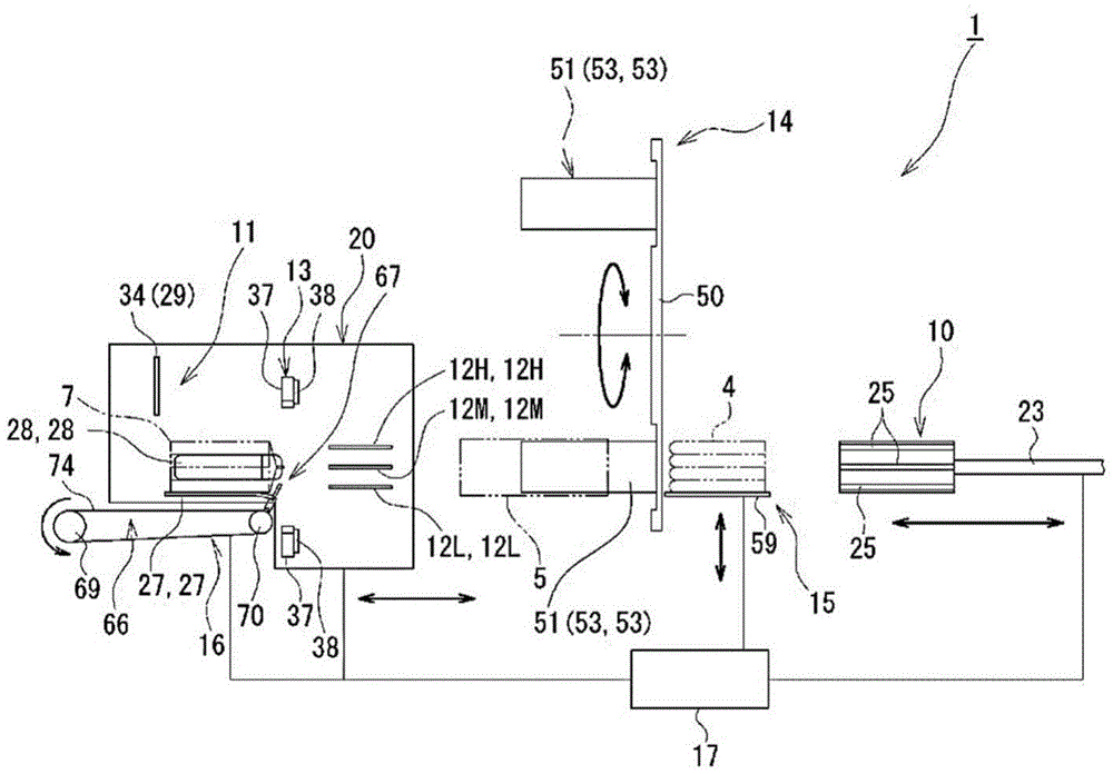
The automatic filling and packing apparatus 1 according to the embodiment of the present invention is an apparatus for automatically filling an open end portion of a packing bag 5, in which an object 4 to be packed is closed from one end portion and the other end portion is opened, into the packing bag 5 and sealing the open end portion. As shown in fig. 1, an automatic filling and packaging apparatus 1 according to an embodiment of the present invention includes: a pushing member 10 that pushes the packing material 4 from the open end of the packing bag 5 and fills the packing material; a positioning means 11 that performs positioning in a state where the object 4 to be packed is filled into the packing bag 5 by the pushing member 10; a pair of left and right upper gusseting claws 12H, a pair of left and right intermediate gusseting claws 12M, and a pair of left and right lower gusseting claws 12L, 12L that fold the open end portion of the packaging bag 5 into a gusset shape after the packaging material 4 is filled into the packaging bag 5 by the pushing member 10; a bladed sealing device 13 that presses, heats, and seals the portions folded into a gusset shape by the pair of left and right upper gusset tabs 12H, the pair of left and right intermediate gusset tabs 12M, and the pair of left and right lower gusset tabs 12L, and cuts off the remaining portion on the tip side from the sealed portion; a bag supply device 14 provided upstream of the pair of left and right upper gussets 12H, the pair of left and right intermediate gussets 12M, and the pair of left and right lower gussets 12L, and supplying the packaging bag 5; a packaged article supplying device 15 which is provided on the upstream side of the bag supplying device 14 and supplies the packaged article 4; a discharge device 16 that discharges the article 7, in which the packaging material 4 is filled in the packaging bag 5 and the open end of the packaging bag 5 is sealed, to the outside; and an operation control device 17 that controls the operation of each of the above-described components.
Referring also to fig. 2, the pushing member 10 is formed in a rectangular parallelepiped shape in outer shape. The front face shape of the urging member 10 is formed substantially rectangular. The front shape is a shape of an opening posture when the opening end of the packaging bag 5 is opened. A plate-like sliding portion 23 is connected to one end surface of the pushing member 10 in the longitudinal direction. The plate-shaped sliding portion 23 is thin and extends in the longitudinal direction of the pushing member 10. The pushing member 10 is configured to be movable forward and backward in the longitudinal direction thereof by the movement of the plate-like sliding portion 23 driven by a driving device, not shown. The drive device is electrically connected to the operation control device 17, and operates in accordance with a signal from the operation control device 17.
Relief grooves 25, 25 are formed in both side surfaces of the pushing member 10 in the advancing/retreating direction. The relief grooves 25, 25 are formed at three positions at intervals in the vertical direction. The relief grooves 25, 25 are formed over the entire area in the advancing/retreating direction of the pushing member 10. The relief grooves 25, 25 are of the same depth. On both side surfaces of the pushing member 10, a pair of left and right upper gusset claws 12H, 12H are respectively accommodated in relief grooves 25, 25 in the upper part thereof. On both side surfaces of the pushing member 10, a pair of left and right lower corner- support claws 12L, 12L are respectively accommodated in relief grooves 25, 25 in the lower portion thereof.
As shown in fig. 3 to 5, referring also to fig. 1, the positioning means 11 is for positioning the temporary package 6 filled in the packaging bag 5 at a predetermined position until the open end portion of the packaging bag 5 is sealed by the knife sealing device 13 in a state where the package 4 is pushed into the temporary package 6 by the pushing member 10. The positioning device 11 includes: a pair of base plates 27 and 27 (see fig. 3) on which the temporary packaged objects 6 are placed, a pair of side guides 28 and 28 (see fig. 4) positioned so as to sandwich the temporary packaged objects 6 from both side surfaces, and a stopper member 29 (see fig. 5) for restricting the movement of the temporary packaged objects 6 toward the downstream side. As shown in fig. 3, the substrate 27 is formed in a substantially rectangular shape. A linear space 30 is formed between the pair of substrates 27, 27. In the space 30, a shaft portion 78 of a stopper member 67 of the discharge device 16, which will be described later, is disposed so as to be relatively movable. The space 30 has a width enough to allow insertion of a stopper 79 of a stopper member 67 of the ejector 16, which will be described later. The upstream end of each substrate 27, 27 extends obliquely downward.
As shown in fig. 1 and 4, a pair of side guides 28, 28 are provided above the substrates 27, spaced apart from each other, and standing substantially in parallel. As shown in fig. 4, each side guide 28 is formed in a thin, elongated, substantially rectangular plate shape. The upstream end of each side guide 28 extends slightly obliquely outward. As a result, the pair of side guides 28 and 28 are formed in a figure-eight shape in plan view such that the distance between the pair of side guides 28 and 28 gradually increases toward the upstream side. The pair of side guides 28, 28 are configured to be movable toward and away from each other by driving of the corresponding servo motors 31, 31. The servo motors 31, 31 are electrically connected to the motion control device 17, and operate in response to signals from the motion control device 17.
As shown in fig. 1 and 5, referring also to fig. 12, the stopper member 29 is formed in an L-shape composed of a substantially rectangular connecting plate-like portion 33 connected to the cylinder 35, and a stopper portion 34 connected integrally to the connecting plate-like portion 33 and contacting the bottom surface (downstream side surface) of the temporary package 6. The stopper portion 34 is formed in a substantially rectangular shape. The stopper member 29 (stopper portion 34) is configured to be movable in the vertical direction by driving of the cylinder 35. Further, a servo motor may be used instead of the cylinder 35. The stopper member 29 (stopper portion 34) is configured to be movable forward and backward relative to the unit body 20, which will be described later, in the same direction as the forward and backward direction of the pushing member 10 by driving of a driving device (not shown). The cylinder 35 and the driving device are electrically connected to the operation control device 17, and operate in response to signals from the operation control device 17.
In the positioning device 11, when the temporary package 6 is disposed on the pair of base plates 27, the pair of side guides 28, 28 are moved in the direction to approach each other, and both side surfaces of the temporary package 6 are supported by the pair of side guides 28, whereby the temporary package 6 is positioned with respect to the left-right direction thereof. The stopper portion 34 of the stopper member 29 moves downward and upstream, abuts against the bottom surface (downstream surface) of the temporary packaged object 6 on the pair of base plates 27, and regulates the movement of the temporary packaged object 6 toward the downstream side, whereby the temporary packaged object 6 is positioned with respect to the traveling direction thereof.
Then, in the state of the temporary package 6, the temporary package 6 is positioned at a predetermined position on the pair of base plates 27, 27 by the positioning device 11 (i.e., the pair of side guides 28, 28 and the stopper portion 34 of the stopper member 29) until the opening end portion of the packaging bag 5 is sealed by the knife seal device 13. When the open end of the packaging bag 5 is sealed by the knife sealer 13, the pair of side guides 28, 28 move in directions away from each other, and move away from both side surfaces of the article 7. The stopper portion 34 of the stopper member 29 moves upward and downstream, and is away from the bottom surface (downstream surface) of the article 7. As a result, the positioning of the article 7 by the positioning device 11 is released.
As shown in fig. 1, a knife seal device 13 is disposed on the upstream side of the positioning device 11. Referring also to fig. 6, the bladed sealing device 13 includes a pair of upper and lower sealing bodies 37, and a pair of upper and lower cutter members 38, 38 provided on the upstream surfaces of the pair of sealing bodies 37, 37. The pair of upper and lower seal bodies 37 and 37 are configured to be movable in directions toward and away from each other by driving of a driving device, not shown. The drive device is electrically connected to the operation control device 17 and operates in accordance with a signal from the operation control device 17. The opening end portion of the temporary package 6 folded into a gusset shape can be sealed by being sandwiched between the pair of upper and lower sealing bodies 37, 37 and pressed and heated.
The pair of upper and lower cutter members 38, 38 are configured to be movable in directions to approach and separate from each other by driving of the cylinders 41, 41. The cylinders 41 and 41 are electrically connected to the operation control device 17, and operate in response to a signal from the operation control device 17. Further, by making the pair of upper and lower cutter members 38, 38 approach each other and intersect each other, the remaining portion on the tip side from the sealed portion can be cut. The knife seal device 13 further includes a suction nozzle 40 connected to the upper seal body 37 and the upper cutter member 38. The suction nozzle 40 is connected to a suction device (not shown). This allows the remaining portion on the distal end side cut by the pair of upper and lower cutter members 38, 38 to be discharged to the outside through the suction nozzle 40.
As shown in fig. 1, a pair of left and right upper gusset tabs 12H, a pair of left and right intermediate gusset tabs 12M, and a pair of left and right lower gusset tabs 12L, 12L are disposed on the upstream side of the knife edge sealing device 13. Referring also to fig. 7, the upper gusset claws 12H and 12H are disposed in a pair on the left and right, at the upper part. The upper gusset tab 12H is formed by providing a thin plate material with a predetermined width in the lateral direction. The upper gusset claw 12H extends along the moving direction of the pushing member 10. The bladed seal device 13 is disposed on the tip end side of the upper gusset tab 12H. The lower gusset tabs 12L, 12L are disposed in a pair on the left and right at the lower part. The lower gusset tab 12L is formed by providing a thin plate material with a predetermined width in the lateral direction. The lower gusset claw 12L extends along the moving direction of the pushing member 10. A bladed seal device 13 is disposed on the distal end side of the lower gusset tab 12L.
The upper and lower pair of upper and lower gusset tabs 12H, 12L are disposed at positions overlapping in the vertical direction. The upper and lower pair of upper and lower angle braces 12H, 12H and lower angle braces 12L, 12L are configured to be movable toward and away from each other by driving of the servo motors 42, 42. The servo motors 42, 42 are electrically connected to the motion control device 17, and operate in response to a signal from the motion control device 17. The intermediate gusset claws 12M, 12M are located at the vertically intermediate position between the upper gusset claw 12H and the lower gusset claw 12L, and are arranged in a pair on the left and right. The intermediate gusset tab 12M is formed by providing a thin plate material with a predetermined width in the lateral direction. The intermediate gusset claw 12M extends along the moving direction of the pushing member 10. A bladed seal device 13 is disposed on the tip end side of the intermediate gusset tab 12M. The pair of left and right intermediate support claws 12M and 12M are configured to be movable toward and away from each other by driving of a driving device, not shown. The drive device is electrically connected to the operation control device 17 and operates in accordance with a signal from the operation control device 17.
Then, as shown in fig. 8(a), the pair of left and right upper gussets 12H, 12H and the pair of left and right lower gussets 12L, 12L are inserted into four corners of the open end of the packaging bag 5. Fig. 8(a) is a diagram showing a state in which the pushing member 10 is inserted into the packaging bag 5. Thus, the open end of the packaging bag 5 is supported from the inside in a substantially rectangular open posture. Substantially simultaneously with this, the pair of left and right intermediate gusset claws 12M, 12M are respectively arranged in the vicinity of the vertical center position of both side surfaces of the opening end portion in a state of being opened in a substantially rectangular shape.
Then, as shown in fig. 8(b), the pair of left and right intermediate gusset claws 12M, 12M are moved from their positions so as to approach each other, and the pair of upper gusset claws 12H, 12H and the pair of lower gusset claws 12L, 12L are moved so as to approach each other until they are positioned at positions substantially overlapping with the pair of left and right intermediate gusset claws 12M, 12M in the horizontal direction. As a result, the open end of the packaging bag 5 can be folded into a gusset shape by the pair of left and right upper gusset claws 12H, the pair of left and right intermediate gusset claws 12M, and the pair of left and right lower gusset claws 12L, 12L.
As shown in fig. 1, the bag supply device 14 is disposed upstream of the pair of left and right upper gussets 12H, the pair of left and right intermediate gussets 12M, and the pair of left and right lower gussets 12L, 12L. The bag supply device 14 includes a rotating member 50, and a plurality of bag support members 51, 51 arranged on an upstream surface of the rotating member 50 at intervals in the circumferential direction. The rotary member 50 is driven by a driving device, not shown, to alternately rotate in the forward and reverse directions at half-cycle intervals. The drive device is electrically connected to the operation control device 17 and operates in accordance with a signal from the operation control device 17.
The bag support members 51, 51 are provided in a plurality projecting from the upstream surface of the rotating member 50 toward the unit body 20, which will be described later, at intervals in the circumferential direction. In the present embodiment, the bag support members 51, 51 are provided at two places at a 180 ° pitch. The bag support member 51 supports the packaging bag 5 in an opened state. Specifically, the packaging bag 5 is covered around the bag support member 51 from the open end thereof. The packaging bag 5 is covered around the bag support member 51, and faces the pusher member 10 with its open end opened in a substantially rectangular shape. The bag support member 51 is configured by arranging a pair of split support members 53 and 53 having an コ -shaped cross section in such a direction that their open sides face each other. Further, an opening portion having a substantially rectangular shape in front view is formed between the pair of divided supporting members 53, 53.
The pair of divided support members 53 and 53 are provided so as to penetrate the rotating member 50. The pushing member 10 moves between the pair of divided supporting members 53 and 53 to advance and retreat. As a result, the object to be packed 4 is pushed by the pushing member 10 and moves between the pair of divided supporting members 53 and 53 toward the unit main body 20 described later. Then, the rotating member 50 rotates half a turn in the forward direction, and the bag support member 51 is positioned upward. Next, the packaging bag 5 is covered around the bag support member 51 from the open end thereof by a bag attachment device not shown. Then, the rotating member 50 rotates in the reverse direction by half a turn, and the bag support member 51 covering the packaging bag 5 is positioned downward. In this state, the pushing member 10 moves in the bag support member 51 via the rotating member 50 while pushing the object to be packed, thereby pushing the object to be packed 4 into the temporary packing material 6 filled in the packaging bag 5. Then, the temporary package 6 is placed on the pair of base plates 27, 27 of the positioning device 11 of the unit body 20 that advances so as to approach the pushing member 10.
As shown in fig. 1, the object-to-be-packed supplying device 15 is disposed on the upstream side of the bag supplying device 14. Referring also to fig. 9, the object-to-be-packaged feeding device 15 includes: a conveyor belt 57 having a plurality of partition plates 56, 56 standing at intervals, a throw-in pusher 58 that moves while pressing the objects to be packed 4 disposed between the partition plates 56, 56 of the conveyor belt 57, and a receiving member 59 that receives the objects to be packed 4 moved by the throw-in pusher 58. The conveyor belt 57 extends in a direction substantially orthogonal to the moving direction of the input pushing member 58. The conveyor 57 sequentially conveys the objects to be packed 4 between the partition plates 56, 56 to the front of the throw-in pusher 58 at a time interval. A driving device (not shown) of the conveyor 57 is electrically connected to the operation control device 17 and operates in response to a signal from the operation control device 17.
A plurality of partition plates 56, 56 stand on the conveyor belt 57 at intervals. The object 4 to be packed is placed between the partition plates 56, 56. The input pushing member 58 is disposed below the pushing member 10. The input pushing member 58 is configured to be movable forward and backward in the same direction as the pushing member 10 by driving of a driving device, not shown. The drive device is electrically connected to the operation control device 17 and operates in accordance with a signal from the operation control device 17. The input pushing member 58 includes a substantially rectangular upper plate 62 and a pushing plate 63 extending downward from an end of the upper plate 62.
The receiving member 59 is disposed at a position facing the moving direction of the input pushing member 58. The receiving member 59 is configured to be movable forward and backward in the vertical direction by driving of a driving device not shown. The drive device is electrically connected to the operation control device 17 and operates in accordance with a signal from the operation control device 17. Then, the object to be packed 4 placed between the partition plates 56, 56 of the conveyor 57 is conveyed to a position facing the push-out plate 63 of the input pushing member 58 by driving the conveyor 57. Then, the input pushing member 58 advances, whereby the upper plate 62 thereof is positioned above the object to be packed 4, and the object to be packed 4 is pushed out into the receiving member 59 by the pushing plate 63. Next, the receiving member 59 is moved upward by the driving of the driving device, and thereby the object 4 is supplied to a position facing the pushing member 10 (see fig. 1).
As shown in fig. 1, the positioning device 11, the bladed seal device 13, the pair of left and right upper gussets 12H, the pair of left and right intermediate gussets 12M, and the pair of left and right lower gussets 12L, 12L are configured as a unit body 20 that is unitized by being connected to each other using a plurality of connecting members, frames, and the like, not shown. The unit main body 20 is configured to be movable in a horizontal direction (i.e., in a direction of approaching and separating) with respect to the pushing member 10 by driving of a driving device (not shown). The drive device is electrically connected to the operation control device 17 and operates in accordance with a signal from the operation control device 17. The moving direction of the unit body 20 and the moving direction of the pushing member 10 are on the same line along the horizontal direction.
The unit body 20 is formed by unitizing the positioning device 11, the bladed seal device 13, the pair of left and right upper gussets 12H, the pair of left and right intermediate gussets 12M, and the pair of left and right lower gussets 12L, so that the unit body 20 can perform the following three steps while moving: a step of filling the package 4 into the packaging bag 5 while opening the knife seal 13 and performing positioning in this state; a step of folding the open end of the packaging bag 5 into a gusset shape; and a step of sealing and cutting the folded member. As shown in fig. 1, the apparatus further includes a discharge device 16 for discharging the packaged article 7 from the unit body 20 in a predetermined direction by the operation of the unit body 20 and the pushing member 10.
As shown in fig. 1 and 10, the discharge device 16 includes: a discharge body 66 for receiving the article 7 and discharging the article in a predetermined direction; and a stopper member 67 provided so as to be able to protrude upward from the upstream end of the discharge body 66. The discharge body 66 includes: a pair of drive shafts 69, 69 provided on the downstream side; a pair of driven shafts 70, 70 provided on the upstream side and rotatably supported; a support base 71 provided between each of the drive shafts 69, 69 and each of the driven shafts 70, 70; and a discharge belt 74 wound around the drive shaft 69, the support base 71, and the driven shaft 70. The discharge belts 74, 74 are arranged in 2 strips at intervals. Reference numeral 75 denotes a servomotor for rotationally driving the drive shaft 69. By the rotation of these drive shafts 69, the discharge belts 74, 74 rotate around the support base 71. The servo motors 75, 75 are electrically connected to the motion control device 17, and operate in response to a signal from the motion control device 17.
The discharge belts 74, 74 (the respective drive shafts 69, 69) rotate in a direction in which the articles 7 on the discharge belts 74, 74 are discharged by being separated from the stopper member 67. The stopper member 67 includes a shaft portion 78 and a T-shaped stopper portion 79 connected to an end of the shaft portion 78. The stopper member 67 is disposed between the pair of driven shafts 70, 70. A cylinder, not shown, is connected to the shaft portion 78 of the stopper member 67. By driving the cylinder, the stopper portion 79 of the stopper member 67 is freely moved upward and downward from the support base 71 of the discharge main body 66. The cylinder is electrically connected to the operation control device 17, and operates in response to a signal from the operation control device 17. Further, a servo motor may be used instead of the cylinder. As is apparent from fig. 1, when the unit main body 20 is retracted to the initial position, the pair of substrates 27 and 27 of the positioning device 11 provided in the unit main body 20 are disposed directly above the discharge main body 66 of the discharge device 16.
As described above, the operation control device 17 is electrically connected to the drive devices such as the servo motor and the cylinder provided correspondingly to the pushing member 10, the positioning device 11, the pair of left and right upper gusset claws 12H and 12H, the pair of left and right intermediate gusset claws 12M and 12M, and the pair of left and right lower gusset claws 12L and 12L, the knife sealing device 13, the bag supply device 14, the packed material supply device 15, the discharge device 16, and the unit main body 20, in order to operate. Although not shown in the drawings, the automatic filling and packaging apparatus 1 is provided with a plurality of detection sensors such as photoelectric sensors for detecting the movement of the respective components, the passage of the package, and the like, and detection signals from the detection sensors are transmitted to the operation control device 17.
The operation control device 17 controls the operations of the pushing member 10, the positioning device 11, the pair of left and right upper gusset claws 12H, the pair of left and right intermediate gusset claws 12M, and the pair of left and right lower gusset claws 12L, the knife sealing device 13, the bag supply device 14, the device 15 for supplying an object to be packed, the discharge device 16, and the unit main body 20, based on the detection results from the respective detection sensors. The control method of the operation control device 17 will be described in detail below.
Next, the operation (action) of the automatic filling and packaging apparatus 1 according to the embodiment of the present invention, that is, the control method of the operation control device 17 will be described with reference to fig. 1 as appropriate based on fig. 11 to 14. In the following description, the operations of the unit body 20 and the pushing member 10 other than the bag supplying device 14 and the device 15 for supplying an object to be packed will be described in detail.
First, the state of fig. 11 is a state in which the unit body 20 is retracted to the initial position away from the bag feeding device 14. At this time, the pair of substrates 27 and 27 constituting the positioning device 11 of the unit body 20 and the discharge main body 66 of the discharge device 16 are in a state of being overlapped in the vertical direction. In the state of fig. 11, the article 7 filled with the packed material 4 in the packaging bag 5 and having its opening end sealed is placed on the pair of base plates 27, 27 of the positioning device 11 constituting the unit body 20.
At this time, in the positioning device 11, the pair of side guides 28 and 28 (see fig. 1) are retracted to the initial position away from the article 7, and the stopper portion 34 of the stopper member 29 is also retracted to the initial position away from the article 7. In the discharge device 16, the stopper portion 79 of the stopper member 67 protrudes upward from the discharge main body 66. The pair of left and right upper gusset claws 12H, the pair of left and right intermediate gusset claws 12M, and the pair of left and right lower gusset claws 12L, 12L stand by at the initial positions. The bag supply device 14 stands by with the bag support member 51 positioned below covered with the packaging bag 5 from the open end thereof. In the object-to-be-packed feeding device 15, the receiving member 59 receives the object to be packed 4, and the object to be packed 4 stands by while being lifted to a position facing the pushing member 10. The pushing member 10 stands by in a state of retreating to the initial position.
Next, from the state of fig. 11, as shown in fig. 12, the unit body 20 advances and the pushing member 10 advances in such a manner that the unit body 20 and the pushing member 10 approach each other. First, when the unit main body 20 advances, the pair of base plates 27, 27 of the positioning device 11 advances, and at this time, since the stopper portion 79 of the stopper member 67 of the discharge device 16 projects upward from the discharge main body 66, the movement of the article 7 on the pair of base plates 27, 27 in the same direction as the unit main body 20 is restricted by the stopper portion 79 of the stopper member 67. Therefore, when the pair of base plates 27, 27 advances, the article 7 moves from the respective base plates 27, 27 to the discharge body 66 of the discharge device 16 by its own weight in conjunction with the advance. The articles 7 are then guided in the discharge direction by the rotation of the respective discharge belts 74, 74 of the discharge device 16.
Further, the stopper portion 79 of the stopper member 67 is in a state of being retracted downward from the discharge main body 66 until the unit main body 20 is retracted to the initial position after being advanced to the maximum extent, and the stopper portion 79 of the stopper member 67 projects upward from the discharge main body 66 at the time when the unit main body 20 is retracted to the initial position. Further, even in a state where the stopper portion 79 of the stopper member 67 protrudes upward from the discharge main body 66, the shaft portion 78 of the stopper member 67 is disposed in the space portion 30 between the pair of substrates 27, 27 of the positioning device 11 of the unit main body 20 so as to be relatively movable, and therefore, the forward movement of the unit main body 20 (the pair of substrates 27, 27) is not hindered.
On the other hand, when the pushing member 10 advances, the pushing member 10 advances while pushing out the object to be packed 4 on the receiving member 59 of the object to be packed supplying device 15, passes through the rotating member 50 and the bag supporting member 51 of the bag supplying device 14, pushes the object to be packed 4 into the packaging bag 5, and at the same time, pulls the packaging bag 5 away from the bag supporting member 51, and guides the temporary package 6 onto the pair of base plates 27, 27 of the positioning device 11 of the unit body 20 that has advanced. Substantially simultaneously with this, the stopper portion 34 of the stopper member 29 of the positioning device 11 moves to a position of contact with the bottom surface (downstream side surface) of the temporary package 6, thereby restricting further movement of the temporary package 6 by the pushing member 10. The pair of side guides 28, 28 of the positioning device 11 move so as to approach each other, and support the temporary packages 6 from both side surfaces, so that the temporary packages 6 are positioned on the pair of base plates 27, 27. Further, the unit body 20 and the pushing member 10 advance to the maximum extent, and substantially simultaneously with the pushing member 10 filling the packing material 4 into the packing bag 5, the packing bag 5 is covered with the periphery of the bag support member 51 located above the rotating member 50 from the open end portion thereof by a bag attaching means not shown.
In this way, when the unit body 20 and the pushing member 10 advance to the maximum extent and the pushing member 10 pushes the object 4 into the packaging bag 5, referring to fig. 8(a), the pair of upper left and right gusset claws 12H and 12H are accommodated in the upper escape grooves 25 and 25 on both side surfaces of the pushing member 10, and the pair of lower left and right gusset claws 12L and 12L are accommodated in the lower escape grooves 25 and 25 on both side surfaces of the pushing member 10. At this time, while the pushing member 10 is still inserted into the packaging bag 5, the pair of left and right upper gusset claws 12H, 12H and the pair of left and right lower gusset claws 12L, 12L are inserted into four corners of the opening end of the packaging bag 5. In this way, the open end of the packaging bag 5 is held from the inside in a substantially rectangular open posture by the pair of left and right upper gussets 12H, 12H and the pair of left and right lower gussets 12L, 12L.
Next, as shown in fig. 13, when the pushing member 10 completely retreats from the inside of the packaging bag 5 after the packaging material 4 is filled in the packaging bag 5 by the pushing member 10, referring to fig. 8(b), the pair of left and right intermediate gusset claws 12M, 12M are disposed in the vicinity of the center position in the vertical direction of both side surfaces of the opening end portion of the packaging bag 5 in a state where the opening is substantially rectangular, and are moved so as to approach each other from this position, and the pair of upper and lower gusset claws 12H, 12H and the pair of lower gusset claws 12L, 12L are moved so as to approach each other to a position substantially overlapping the pair of left and right intermediate gusset claws 12M, 12M in the horizontal direction. As a result, the open end of the packing bag 5 is folded into a gusset shape. Then, the pushing member 10 is retreated to the initial position via the inside of the bag supporting member 51 including the rotating member 50.
On the other hand, as shown in fig. 13, the unit main body 20 starts to retreat while maintaining the state after the open end portion of the temporary package 6 is folded into a gusset shape by the pair of left and right upper gusset claws 12H, the pair of left and right intermediate gusset claws 12M, and the pair of left and right lower gusset claws 12L, 12L. Then, the unit main body 20 is retreated, and at the same time, a portion of the temporary packaged object 6, which is on the downstream side of the distal ends of the pair of left and right upper gusset claws 12H, the pair of left and right intermediate gusset claws 12M, and the pair of left and right lower gusset claws 12L, of the gusset-shaped opening end portion, is sandwiched by the pair of upper and lower sealing main bodies 37, 37 of the bladed sealing device 13, and is pressed and heated, thereby performing sealing.
At substantially the same time, the upper and lower pair of cutter members 38, 38 of the bladed sealing device 13 are made to approach each other and intersect, thereby cutting the remaining portion of the leading end side from the sealed portion of the article 7. The remaining portions of the cut distal end side are separated from the pair of left and right upper gusset tabs 12H, the pair of left and right intermediate gusset tabs 12M, and the pair of left and right lower gusset tabs 12L, and are sucked by the suction nozzle 40 (see fig. 6) and discharged to the outside. Thus, while the unit body 20 is retreated and returned to the initial position, the upper and lower pair of seal bodies 37, 37 of the bladed seal device 13 can press and heat the temporarily packed objects 6 while sandwiching the gusset-shaped open end portions therebetween.
Then, as shown in fig. 14, when the unit body 20 is retracted to the initial position, the packaged article 7 is placed on the pair of base plates 27, 27 of the positioning device 11. At this time, as in the state of fig. 11, the positioning device 11, the pair of left and right upper gusset claws 12H, the pair of left and right intermediate gusset claws 12M, the pair of left and right lower gusset claws 12L, and the bladed seal device 13 constituting the unit body 20 are returned to the initial positions. The pushing member 10 is also in a state of retreating to the initial position. In the bag supply device 14, the rotating member 50 rotates half a turn in the forward direction or the reverse direction, and the bag support member 51 covering the packaging bag 5 is positioned downward. In the object-to-be-packaged feeding device 15, the receiving member 59 places the object to be packaged 4 thereon and ascends to a position facing the pushing member 10. On the other hand, in the discharge device 16, the stopper portion 79 of the stopper member 67 projects upward from the discharge main body 66 of the discharge device 16.
Then, when the unit body 20 advances again together with the pushing member 10, the above-described operation is repeated (see fig. 12 to 14). By repeating this operation, the packing material 4 is filled into the packing bag 5, and the articles 7 obtained by sealing the opening end of the packing bag 5 in a gusset shape sequentially reach the discharge device 16 from the unit body 20, and are guided in the discharge direction by the discharge device 16.
As described above, in the automatic filling and packaging apparatus 1 according to the embodiment of the present invention, the positioning device 11, the pair of left and right upper gusset tabs 12H, the pair of left and right intermediate gusset tabs 12M, the pair of left and right lower gusset tabs 12L, and the bladed seal device 13 are formed as the unit main body 20, and the unit main body 20 and the pushing member 10 are formed to be movable in the horizontal direction so as to be able to move toward and away from each other. Thus, a series of operations of filling the package 4 into the packaging bag 5, folding the open end of the packaging bag 5 into a gusset shape, and sealing the opening can be performed while the unit body 20 and the pushing member 10 are moved toward and away from each other.
As a result, the total time required for filling one packaging bag 5 with one object 4 and sealing the open end of the packaging bag 5 can be shortened as compared with the conventional art, and the packaging efficiency can be improved. Further, when the open end of the packaging bag 5 is to be gusseted, the pair of left and right upper gusseting claws 12H, the pair of left and right intermediate gusseting claws 12M, and the pair of left and right lower gusseting claws 12L, 12L are used, so that variation in the finish process of the sealed portion can be suppressed as compared with the conventional one, and the yield can be improved.
In the automatic filling and packaging apparatus 1 according to the embodiment of the present invention, the moving direction of the unit body 20 and the moving direction of the pushing member 10 are on the same line. This simplifies the operation steps of the automatic filling and packaging apparatus 1, and increases the production speed of the automatic filling and packaging apparatus 1.
Further, in the automatic filling and packing apparatus 1 according to the embodiment of the present invention, when the unit body 20 and the pushing member 10 approach each other, the object 4 to be packed is pushed in from the opening end portion of the packing bag 5 by the pushing member 10 and is filled. On the other hand, when the unit body 20 and the pushing member 10 are moved away from each other, the unit body 20 is retreated while the opening end portion of the packaging bag 5 folded into a gusset shape is sealed by the bladed sealing device 13. Accordingly, for example, even in the case of high-speed operation, the sealing time by the blade sealing device 13 can be obtained, and therefore, occurrence of a sealing failure can be suppressed, and the yield can be improved.
In this way, in the automatic filling and packaging apparatus 1 according to the embodiment of the present invention, the unit body 20 and the pushing member 10 are moved, and the following three steps are performed: a step of filling the packaging bag 5 with the object 4 to be packaged while opening the knife seal device 13, and positioning the packaging bag in this state; folding the open end of the packaging bag 5 into a gusset shape; and sealing and cutting the folded part. This can significantly reduce the total time required for filling one package bag 5 with one object 4 and sealing the opening end of the package bag 5, thereby further improving the packaging efficiency. Further, even in the case of high-speed operation, sealing failure can be suppressed, and the yield is good, so that the packaging work efficiency can be further improved, and the reliability can be improved in the packaging work.
In short, the automatic filling and packaging apparatus 1 according to the embodiment of the present invention does not include a step of discharging the articles, that is, a step of discharging the packaged articles, which is unreliable for speeding up, and a step of operating the knife edge sealing device 13, compared to the conventional apparatus, and thus can significantly reduce the total time required for filling one package 4 into one package 5 and sealing the opening end of the package 5, can easily cope with speeding up, and can suppress the occurrence of defective products such as sealing failure, compared to the conventional apparatus.
Further, in the automatic filling and packing device 1 according to the embodiment of the present invention, the pushing member 10 is formed in a substantially rectangular parallelepiped shape, and the pair of left and right upper gusset claws 12H, 12H and the pair of left and right lower gusset claws 12L, 12L are formed in both side surfaces of the pushing member 10 in the advancing and retreating direction in the escape grooves 25, respectively, in the entire region in the advancing and retreating direction. Thus, while the pushing member 10 is inserted into the packaging bag 5, the pair of left and right upper gussets 12H, 12H and the pair of left and right lower gussets 12L, 12L can be inserted into the open end of the packaging bag 5. As a result, the open end of the packaging bag 5 can be easily held in a substantially rectangular open posture by the pair of left and right upper gusseting claws 12H, 12H and the pair of left and right lower gusseting claws 12L, 12L.
Further, the automatic filling and packing apparatus 1 according to the embodiment of the present invention includes the discharge device 16 for discharging the article 7 in which the packing material 4 is filled in the packing bag 5 and the opening end portion of the packing bag 5 is sealed from the unit body 20, and the discharge main body 66 of the discharge device 16 is configured to be vertically overlapped with the pair of substrates 27 and 27 of the positioning device 11 of the unit body 20 when the unit body 20 is retreated to the initial position. Thus, when the unit body 20 is retracted to the initial position, the article 7 held by the unit body 20 can be easily moved by its own weight to the discharge main body 66 of the discharge device 16. This eliminates the need for a new moving device or the like for moving the article 7 from the unit body 20 to the discharge device 16, and can simplify the structure. Further, in this way, in the process of moving the unit body 20 and the pushing member 10 toward and away from each other, the operation of cutting the packaged article 7 from the unit body 20 can be performed in parallel in a series of operation steps of filling the package bag 5 with the object 4, folding the opening end portion of the package bag 5 into a gusset shape, and sealing the place, and a high speed can be coped with.
Further, in the automatic filling and packaging apparatus 1 according to the embodiment of the present invention, the discharge device 16 includes a stopper member 67 that restricts the movement of the article 7 when the unit body 20 advances. Thus, when the unit body 20 advances, the stopper member 67 can easily pull the article 7 away from the unit body 20 and move the article to the discharge device 16 in conjunction with the advancing operation.
Further, in the automatic filling and packing device 1 according to the embodiment of the present invention, after the pushing member 10 advances to fill the packing material 4 into the packing bag 5, the open end of the packing bag 5 is supported in the substantially rectangular open posture by the pair of left and right upper gussets 12H, 12H and the pair of left and right lower gussets 12L, 12L before completely retreating from the packing bag 5. As a result, the open end of the packaging bag 5 can be easily formed into a substantially rectangular shape along the front shape (substantially rectangular shape) of the pushing member 10. Thus, the opening posture is easily formed into a substantially rectangular shape and easily maintained by the pair of left and right upper gusset claws 12H, 12H and the pair of left and right lower gusset claws 12L, 12L.
Further, in the automatic filling and packaging apparatus 1 according to the embodiment of the present invention, the open end of the packaging bag 5 is folded into a gusset shape by the pair of left and right upper gusset claws 12H, the pair of left and right intermediate gusset claws 12M, and the pair of left and right lower gusset claws 12L, 12L. As a result, compared to the conventional art in which a plurality of suction holes provided in the pushing member are provided in order to fold the pushing member into a gusset shape, and a suction tube including an air supply source connected to the suction holes is provided, the processing cost of the pushing member can be reduced, and the suction tube is not required, so that the facility cost as a whole can be reduced.
Description of reference numerals
1 automatic filling and packaging device;
4, packaging the materials;
5, packaging bags;
6 temporary packing materials;
7, articles;
10 a pushing member;
11 a positioning device;
12H upper angle support claws;
12M middle angle support claw;
12L lower gusset claws;
13 a bladed seal;
16 an evacuation device;
17 an action control device;
20 a unit body;
25 withdrawing the yield groove;
67 a stopper member;
79 stop part.