Plastic film cutting equipment and cutting method
Technical Field
The invention belongs to the technical field of plastic film preparation, and particularly relates to plastic film cutting equipment and a plastic film cutting method.
Background
The plastic film is a film made of polyvinyl chloride, polyethylene, polypropylene, polystyrene and other resins, and is used for packaging and as a film coating layer; the production specifications of the plastic films are different from manufacturer to manufacturer, and generally the plastic films have the specifications of 3, 10, 20, 30, 40, 50 and the like, and the thickness of the plastic film with the specification of 50 is 0.5 mm in short. In the production process of the plastic film, the plastic film which is prepared and wound into a shape needs to be cut to obtain the plastic film with the required size, and then the plastic film is packaged; the film cutting machine in the prior art generally has good application value in the aspect of film cutting, but with the continuous increase of the width of the film and the corresponding influence on the cutting performance, the optimization and the improvement of the semi-automatic film cutting machine are imperative.
In the prior art, in the process of cutting a plastic film by cutting equipment, after the position of the plastic film is clearly cut, the plastic film is pressed on a workbench by a pushing mechanism and then moved to a cutting part along the workbench with the plastic film, and the film is cut by an electric film cutting knife along a steel ruler, so that the plastic film is cut. However, when thick plastic films are cut in a large batch, the front pushing mechanism drives the plastic films to move, the rear plastic films are not enough to correct the deviation of the movement tracks of the rear plastic films in the dragging process, so that the rear plastic films deviate in the movement process, the front plastic films are cut, the pushing mechanism moves to the rear plastic films after the rear plastic films deviate, the plastic films are pressed and driven to move to the cutting position, errors are generated in the sizes of the rear plastic films after cutting, the size precision of the cut plastic films is reduced, and the production quality of the plastic films is influenced.
In view of the above, the present invention provides a plastic film cutting apparatus and a plastic film cutting method, which solve the above problems.
Disclosure of Invention
The invention provides plastic film cutting equipment and a plastic film cutting method, aiming at overcoming the defects of the prior art and solving the problems that when thick plastic films are cut in large batch, a front pushing mechanism drives the plastic films to move, and the movement tracks of the rear plastic films are not corrected enough in the dragging process of the rear plastic films, so that the rear plastic films deviate in the movement process, the sizes of the rear plastic films after being cut generate errors, and the size precision of the plastic films after being cut is reduced.
The technical scheme adopted by the invention for solving the technical problems is as follows: the invention relates to a plastic film cutting device, which comprises:
a main body;
a motor installed at one side of the main body;
the film cutter is arranged in the middle of the top of the main body;
the conveying rollers are uniformly and rotatably connected to two end positions in the main body, one end, close to the motor, of each conveying roller is connected with the output end of the motor, and the motor is used for driving the conveying rollers to rotate;
the conveying belt is sleeved on the conveying roller;
the supporting plate is fixedly connected in the main body and is positioned between the adjacent conveying rollers;
and the pressing mechanism is used for pressing the plastic films with different widths.
When the cutting device is used, in the process of producing and preparing thicker plastic films, the films are wound into rolls and then enter a cutting procedure, a worker firstly puts one end of the plastic film roll into a main body, the left side of the cutting device is a feeding end, the right side of the cutting device is a discharging end, after the plastic films are placed on a conveying belt from the feeding end, the cutting device is started, a motor drives a conveying roller to rotate, the conveying roller drives the conveying belt to move, the conveying belt drives the plastic films to move towards the direction close to a film cutter, a pressing mechanism on the conveying belt presses the plastic films on the conveying belt, the pressed plastic films move towards the direction close to the film cutter along with the conveying belt, so that one side surface of the plastic film contacting the conveying belt is protected, the neatness of the surface of the plastic film is improved, the problem that the plastic film contacting a worktable in the prior art is dragged to cut is avoided, and the bottom surface of the plastic film contacting the worktable is influenced by friction to generate a large amount of scratches or damages, thereby affecting the aesthetic degree of the finished plastic film; by arranging the pressing mechanism, a worker adjusts the position of the pressing mechanism according to the width of the cut plastic film, after the plastic film moves to the pressing mechanism, the pressing mechanism presses the edges of two sides of the plastic film, so that the position of the plastic film in the moving process towards the film cutter is fixed, the cutting position of the plastic film is accurate, the size precision of the cut plastic film is improved, the cutting effect of the plastic film is improved, the plastic film is prevented from deviating in the moving process, errors are caused in the size of the cut plastic film, and the size precision of the cut plastic film is reduced; the plastic film moves to the position below the film cutter along with the conveying belt, the film cutter cuts the plastic film, and the conveying belt and the plastic film are supported by the supporting plate, so that the plastic film is cut; after the plastic film is cut, the pressing mechanism is separated from the surface of the plastic film, the plastic film moves along with the conveying belt to drop out of the main body, and a worker collects the cut plastic film and performs subsequent treatment.
Preferably, the pressing mechanism includes:
the first holes are uniformly formed in the conveying belt;
the sliding rod is connected in the first hole in a sliding mode and is L-shaped, and the sliding rod is connected with the first hole through a return spring;
the rollers are uniformly and rotatably connected to two sides of the sliding rod and are close to the outer surface of the conveying belt;
the telescopic rods are uniformly fixedly connected to the positions, corresponding to the supporting plates, of the inner walls of the two sides of the main body, one end, far away from the supporting plates, of each telescopic rod penetrates through the inner wall of the main body, and the telescopic rods are used for adjusting the positions of the sliding rods;
the rubber strip, the rubber strip evenly link firmly in on the main part inner wall, just the telescopic link is close to the one end of backup pad with the rubber strip is kept away from one side contact of backup pad.
When the telescopic mechanism is used, when a wide and small plastic film is cut, a worker pushes the telescopic rod into the main body to a specified position according to the width of the plastic film, the telescopic end of the telescopic rod pushes the rubber strip, and the rubber strip is pushed by the telescopic rod to generate elastic deformation so that the telescopic ends of the rubber strips at two sides in the main body, which are in contact with the telescopic rod, are close to each other, so that the worker can quickly adjust the position of the pressing mechanism, and the working strength of the worker is reduced; the conveying belt drives the sliding rods to move, the sliding rods are close to the bottom surface and contact with the rubber strips, the sliding rods slide in the first holes under the guiding action of the surface of the rubber strips, so that the opposite sliding rods are close to each other until the sliding rods move to the edge of the plastic film, the sliding rods drive the rollers to move, the roller positions rotate in a single direction, the rollers contact with the surface of the plastic film and compress the plastic film, when the plastic film deviates to one side, the rollers with opposite deviation directions are influenced by the single-direction rotation of the rollers to pull the plastic film, so that the position of the plastic film is fixed in the movement process, the size precision of the cut plastic film is improved, and the practicability of the cutting equipment for cutting different wide plastic films is improved; after plastic film tailors, the slide bar moves to crossing the rubber strip, and the slide bar is influenced by reset spring and is reset, and the slide bar drives the gyro wheel motion and until keeping away from the plastic film surface, and plastic film moves to dropping out the main part along with the conveyer belt, and the staff collects and carries out subsequent processing to the plastic film after tailorring.
Preferably, the position of the telescopic rod close to the supporting plate is fixedly connected with an adjusting plate.
During the use, through setting up the regulating plate, the staff promotes the telescopic link to the main part is interior according to plastic film's width, the flexible end of telescopic link promotes rubber strip and regulating plate, the rubber strip is promoted by the telescopic link and is influenced the elastic deformation that takes place, the regulating plate restricts the shape after the rubber strip deformation, make the part that the rubber strip is close to the regulating plate keep parallel with main part inner wall, the slide bar moves and is close to each other after contacting rubber strip surface gradually, after the slide bar moves to crossing the telescopic link, the slide bar moves to the part that the rubber strip is parallel with main part inner wall, make plastic film to cut the membrane ware motion in-process, the gyro wheel surface keeps the state that compresses tightly constantly to the plastic film surface, further improve the fixed effect of gyro wheel to plastic film in the motion process, thereby improve the size precision after plastic film cuts out, and then improve plastic film's the effect of tailorring.
Preferably, the outer surface of the roller is uniformly and fixedly connected with anti-skidding blocks.
When the plastic film cutting device is used, the anti-slip blocks are arranged and are fixedly connected to the outer surfaces of the rollers through a plurality of uniform circumferences, the sliding rods drive the rollers to move, the rollers drive the anti-slip blocks to move, the anti-slip blocks move to be in contact with the surfaces of plastic films, the anti-slip blocks can be made by bonding of twill rubber plates, the plastic film cutting device has the advantages of being anti-slip, protective, wear-resistant and the like, the fixing effect of the rollers on the plastic films in the moving process is improved, the size precision of the cut plastic films is improved, and the cutting effect of the plastic films is further improved.
Preferably, the conveyor belt is provided with a first groove.
When the anti-skidding plastic film pressing device is used, a worker places a plastic film in the first groove, the sliding rod slides in the first hole under the guiding action of the surface of the rubber strip until the sliding rod moves to the edge of the plastic film, the sliding rod drives the idler wheel to move, the idler wheel drives the anti-skidding block to move until the anti-skidding block contacts the surface of the plastic film, and the anti-skidding block presses the plastic film tightly; after the plastic film is cut out and is accomplished, the slide bar is influenced by reset spring and is reset, the slide bar drives gyro wheel and non slipping spur and slides on plastic film, plastic film receives a groove spacing can not be pulled by the non slipping spur to make plastic film move to the main part that drops along with the conveyer belt, increase plastic film's discharge efficiency, pull plastic film when avoiding the non slipping spur to reset, thereby lead to the non slipping spur not to break away from plastic film, influence plastic film's discharge.
Preferably, the position of the main body close to the telescopic rod is connected with a limiting plate in a sliding mode, and the limiting plate is L-shaped.
During the use, through setting up the limiting plate, when processing the little plastic film of broad width, the staff slides the limiting plate to being close to the main part internal direction, make interval and plastic film broad width match between two relative limiting plates, plastic film passes and moves to the conveyer belt between two relative limiting plates, the conveyer belt drives plastic film and is close to hold-down mechanism, compress tightly plastic film until hold-down mechanism, thereby it is spacing to carry out plastic film, improve the accuracy that plastic film tailors the position, and then improve plastic film's the effect of tailorring, avoid plastic film to take place the skew when moving to hold-down mechanism, thereby influence plastic film and tailor the accuracy of position.
Preferably, a plurality of convex blocks are uniformly and fixedly connected to the two sides of the conveying belt; a material receiving box is arranged on one side of the main body, which is far away from the telescopic rod, a bottom plate is connected in the material receiving box in a sliding mode, a plurality of sliding grooves are uniformly formed in one side, which is close to the main body, of the material receiving box, a rack is connected in the sliding grooves in a sliding mode, one side, which is far away from the bottom plate, of the rack extends out of the sliding grooves, and the other side of the rack is fixedly connected with the bottom plate;
the inner walls of the material receiving boxes are all subjected to smooth treatment;
a plurality of second grooves are uniformly formed in the inner wall, far away from the main body, of the material receiving box.
When the plastic film cutting device is used, the conveying belt drives the cut plastic film to move to a position close to the material receiving box through the matching between the convex block and the rack, and the plastic film falls into the material receiving box under the influence of motion inertia after being separated from the conveying belt until falling into the material receiving box; the conveying belt drives the lug to move, after the lug moves to a position close to the material receiving box, the top of the lug is contacted with and drives the rack to slide downwards along the sliding groove, the rack cannot slide in the sliding groove under the condition of no external force, the rack slides to drive the bottom plate to slide downwards along the inner wall of the material receiving box, the plastic film on the bottom plate moves downwards along with the bottom plate, the next plastic film continuously moves and falls onto the bottom plate, and the collection efficiency of the cut plastic films is improved;
because the inner wall of the material receiving box is smoothly treated, the plastic film falls into the material receiving box, and two sides of the plastic film move along the inner walls of the two sides of the material receiving box until the plastic film contacts with the inner wall of the material receiving box far away from the main body, the movement effect of the plastic film is increased, and after the two sides of the plastic film contact with the inner wall of the material receiving box, the plastic film does not enter the material receiving box due to overlarge friction force, and the next plastic film falls and is extruded with one plastic film, so that the previous plastic film is indented or folded, and the attractiveness of the plastic film is reduced; through setting up No. two grooves, plastic film moves to the inner wall that the main part was kept away from to the contact collecting box in the collecting box, and plastic film's edge is located No. two inslots for plastic film's corner can not receive collecting box inner wall extrusion formation crease or indentation, thereby improves plastic film's pleasing to the eye degree.
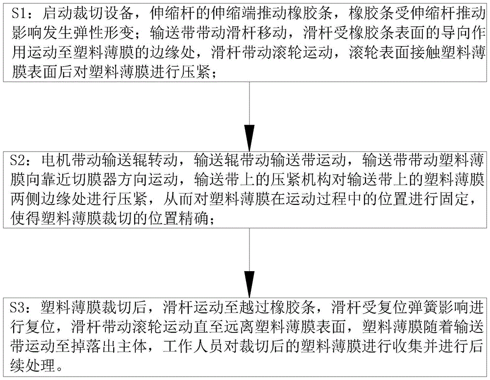
A plastic film cutting method which is applicable to any one of the plastic film cutting apparatuses described above, and which comprises the steps of:
s1: starting the cutting equipment, pushing the rubber strip by the telescopic end of the telescopic rod, and elastically deforming the rubber strip under the influence of the pushing of the telescopic rod; the conveying belt drives the sliding rod to move, the sliding rod moves to the edge of the plastic film under the guiding action of the surface of the rubber strip, the sliding rod drives the roller to move, and the surface of the roller is pressed against the plastic film after contacting the surface of the plastic film;
s2: the motor drives the conveying roller to rotate, the conveying roller drives the conveying belt to move, the conveying belt drives the plastic film to move towards the direction close to the film cutter, and the pressing mechanisms on the conveying belt press the edges of two sides of the plastic film on the conveying belt, so that the position of the plastic film in the moving process is fixed, and the cutting position of the plastic film is accurate;
s3: after plastic film tailors, the slide bar moves to crossing the rubber strip, and the slide bar is influenced by reset spring and is reset, and the slide bar drives the gyro wheel motion and until keeping away from the plastic film surface, and plastic film moves to dropping out the main part along with the conveyer belt, and the staff collects and carries out subsequent processing to the plastic film after tailorring.
The invention has the following beneficial effects:
1. according to the plastic film cutting equipment and the plastic film cutting method, the pressing mechanism is arranged, a worker adjusts the position of the pressing mechanism according to the width of the cut plastic film, after the plastic film moves to the pressing mechanism, the pressing mechanism presses the edges of two sides of the plastic film, and therefore the position of the plastic film in the moving process towards the film cutter is fixed, the cutting position of the plastic film is accurate, the size accuracy of the cut plastic film is improved, and the cutting effect of the plastic film is improved.
2. According to the plastic film cutting equipment and the plastic film cutting method, the anti-slip blocks are arranged, the slide rods drive the rollers to move, the rollers drive the anti-slip blocks to move, the anti-slip blocks move to be in contact with the surfaces of the plastic films, the anti-slip blocks can be made by bonding twill rubber plates, the plastic film cutting equipment has the characteristics of skid resistance, protection, wear resistance and the like, the fixing effect of the rollers on the plastic films in the moving process is improved, the size precision of the cut plastic films is improved, and the cutting effect of the plastic films is further improved.
Drawings
The invention will be further explained with reference to the drawings.
FIG. 1 is a flow chart of a method of the present invention;
FIG. 2 is a perspective view of the present invention;
FIG. 3 is a schematic view of the structure of the conveyor belt of the present invention;
FIG. 4 is a schematic structural view of the present invention;
FIG. 5 is a perspective view of the material receiving box of the present invention;
FIG. 6 is an enlarged view of a portion of FIG. 4 at A;
FIG. 7 is a partial enlarged view at B in FIG. 6;
in the figure: the device comprises a main body 1, a motor 11, a film cutter 12, a conveying roller 13, a conveying belt 14, a supporting plate 15, a first groove 16, a limiting plate 17, a convex block 18, a pressing mechanism 2, a first hole 21, a sliding rod 22, a roller 23, a telescopic rod 24, a rubber strip 25, an adjusting plate 26, an anti-skidding block 27, a material receiving box 3, a bottom plate 31, a sliding groove 32, a rack 33 and a second groove 34.
Detailed Description
In order to make the technical means, the creation characteristics, the achievement purposes and the effects of the invention easy to understand, the invention is further described with the specific embodiments.
As shown in fig. 2 to 7, the plastic film cutting apparatus according to the present invention comprises:
a main body 1;
a motor 11, wherein the motor 11 is arranged on one side of the main body 1;
the film cutter 12 is arranged at the middle position of the top of the main body 1;
the conveying rollers 13 are uniformly and rotatably connected to two ends of the main body 1, one end of each conveying roller 13 close to the motor 11 is connected with the output end of the motor 11, and the motor 11 is used for driving the conveying rollers 13 to rotate;
the conveying belt 14 is sleeved on the conveying roller 13;
the supporting plate 15 is fixedly connected in the main body 1, and the supporting plate 15 is positioned between the adjacent conveying rollers 13;
and the pressing mechanism 2 is used for pressing plastic films with different widths.
When the plastic film cutting machine is used, in the process of producing and preparing thicker plastic films, the films are wound into rolls and then enter a cutting procedure, a worker firstly puts one end of the plastic film roll into the main body 1, the left side of the cutting device is a feeding end, the right side of the cutting device is a discharging end, after the plastic films are placed on the conveying belt 14 from the feeding end, the cutting device is started, the motor 11 drives the conveying roller 13 to rotate, the conveying roller 13 drives the conveying belt 14 to move, the conveying belt 14 drives the plastic films to move towards the direction close to the film cutter 12, the pressing mechanism 2 on the conveying belt 14 presses the plastic films on the conveying belt 14, the pressed plastic films move towards the direction close to the film cutter 12 along with the conveying belt 14, so that one side surface of the plastic films, which is in contact with the conveying belt 14, is protected, the surface neatness of the plastic films is improved, and the problem that the plastic films are dragged to the film cutter 12 to cut in the prior art is avoided, the bottom surface of the plastic film contacting the workbench is influenced by friction to generate a large amount of scratches or damages, so that the attractiveness of a finished plastic film product is influenced; by arranging the pressing mechanism 2, a worker adjusts the position of the pressing mechanism 2 according to the width of the cut plastic film, after the plastic film moves to the pressing mechanism 2, the pressing mechanism 2 presses the edges of two sides of the plastic film, so that the position of the plastic film in the moving process towards the film cutter 12 is fixed, the cutting position of the plastic film is accurate, the size precision of the cut plastic film is improved, the cutting effect of the plastic film is improved, the plastic film is prevented from deviating in the moving process, the size of the cut plastic film generates errors, and the size precision of the cut plastic film is reduced; the plastic film moves to the lower part of the film cutter 12 along with the conveying belt 14, the film cutter 12 cuts the plastic film, and the conveying belt 14 and the plastic film are supported by the supporting plate 15, so that the cutting of the plastic film is completed; after the plastic film is cut, the pressing mechanism 2 is separated from the surface of the plastic film, the plastic film moves along with the conveying belt 14 to fall out of the main body 1, and a worker collects the cut plastic film and performs subsequent processing.
As an embodiment of the present invention, the pressing mechanism 2 includes:
the first holes 21 are uniformly formed in the conveying belt 14;
the sliding rod 22 is connected in the first hole 21 in a sliding mode, the sliding rod 22 is L-shaped, and the sliding rod 22 is connected with the first hole 21 through a return spring;
the rollers 23 are uniformly and rotatably connected to two sides of the sliding rod 22, and the rollers 23 are close to the outer surface of the conveying belt 14;
the telescopic rods 24 are uniformly fixedly connected to the inner walls of the two sides of the main body 1 at positions corresponding to the support plates 15, one end of each telescopic rod 24, far away from the support plate 15, penetrates through the inner wall of the main body 1, and the telescopic rods 24 are used for adjusting the positions of the slide bars 22;
rubber strip 25, rubber strip 25 evenly link firmly on 1 inner wall of main part, just telescopic link 24 is close to the one end of backup pad 15 with one side contact that backup pad 15 was kept away from to rubber strip 25.
When the plastic film cutting machine is used, when a wide and small plastic film is cut, a worker controls the telescopic rod 24 according to the width of the plastic film, so that the telescopic end of the telescopic rod 24 is pushed to an appointed position in the main body 1, at the moment, the telescopic end of the telescopic rod 24 pushes the rubber strip 25, the rubber strip 25 is pushed by the telescopic rod 24 to generate elastic deformation, the telescopic ends of the rubber strips 25 at two sides in the main body 1, which are in contact with the telescopic rod 24, are close to each other, therefore, the worker can quickly adjust the position of the pressing mechanism 2, and the working intensity of the worker is reduced; the conveying belt 14 drives the sliding rods 22 to move, the sliding rods 22 are close to the bottom surface and contact with the rubber strips 25, the sliding rods 22 slide in the first holes 21 under the guiding action of the surface of the rubber strips 25, so that the opposite sliding rods 22 are close to each other until the sliding rods 22 move to the edge of the plastic film, the sliding rods 22 drive the rollers 23 to move, a one-way clamping device is arranged at the rotating joint part of the rollers 23, unidirectional rotation can be realized, the rollers 23 contact with the surface of the plastic film and then press the plastic film tightly, when the plastic film tends to deviate to one side, the rollers 23 with opposite deviation directions are influenced by the one-way rotation to pull and limit the plastic film, so that the position of the plastic film in the moving process is fixed, the size precision of the cut plastic film is improved, and the practicability of the cutting equipment for cutting different wide plastic films is improved; after the plastic film is cut, the sliding rod 22 moves to cross the rubber strip 25, the sliding rod 22 is reset under the influence of the reset spring, the sliding rod 22 drives the roller 23 to move until the surface of the plastic film is far away, the plastic film moves to fall out of the main body 1 along with the conveying belt 14, and a worker collects the cut plastic film and performs subsequent treatment.
In one embodiment of the present invention, an adjusting plate 26 is attached to the telescopic rod 24 near the supporting plate 15.
When the device is used, through the arrangement of the adjusting plate 26, a worker controls the telescopic rod 24 according to the width of the plastic film, so that the telescopic end of the telescopic rod 24 is pushed to a specified position in the main body 1, the telescopic end of the telescopic rod 24 pushes the rubber strip 25 and the adjusting plate 26, the rubber strip 25 is pushed by the telescopic rod 24 to generate elastic deformation, the adjusting plate 26 limits the shape of the deformed rubber strip 25, the part, close to the adjusting plate 26, of the rubber strip 25 is parallel to the inner wall of the main body 1, the sliding rod 22 gradually approaches to each other after moving to contact with the surface of the rubber strip 25, after the sliding rod 22 moves to cross the telescopic rod 24, the sliding rod 22 moves to the part, parallel to the inner wall of the main body 1, the surface of the roller 23 constantly keeps a compression state on the surface of the plastic film in the moving process of the plastic film cutter 12, and the fixing effect of the roller 23 on the plastic film in the moving process is further improved, thereby improving the size precision of the cut plastic film and further improving the cutting effect of the plastic film.
As an embodiment of the invention, anti-skid blocks 27 are uniformly and fixedly connected to the outer surface of the roller 23.
When the plastic film cutting device is used, the anti-slip blocks 27 are arranged, the anti-slip blocks 27 are a plurality of uniform circumferences and are fixedly connected to the outer surface of the roller 23, the sliding rod 22 drives the roller 23 to move, the roller 23 drives the anti-slip blocks 27 to move, the anti-slip blocks 27 move to be in contact with the surface of a plastic film, the anti-slip blocks 27 can be made by bonding of twill rubber plates, the plastic film cutting device has the advantages of being anti-slip, protective, wear-resistant and the like, the fixing effect of the roller 23 on the plastic film in the moving process is improved, the size precision of the cut plastic film is improved, and the cutting effect of the plastic film is further improved.
In one embodiment of the present invention, the conveyor belt 14 is provided with a first groove 16.
When the anti-skidding plastic film pressing device is used, a worker places a plastic film in the first groove 16 through the first groove 16, the sliding rod 22 slides in the first hole 21 under the guiding action of the surface of the rubber strip 25 until the sliding rod 22 moves to the edge of the plastic film, the sliding rod 22 drives the roller 23 to move, the roller 23 drives the anti-skidding block 27 to move until the anti-skidding block 27 contacts the surface of the plastic film, and the plastic film is pressed tightly by the anti-skidding block 27; after plastic film tailors the completion, slide bar 22 is reseed by reset spring influence, slide bar 22 drives gyro wheel 23 and non slipping spur 27 and slides on plastic film, plastic film receives a groove 16 spacing can not be dragged by non slipping spur 27, thereby make plastic film move to the main part 1 that drops along with conveyer belt 14, increase plastic film's discharge efficiency, it drags plastic film to avoid non slipping spur 27 when reseing, thereby lead to non slipping spur 27 not to break away from plastic film, influence plastic film's discharge.
In an embodiment of the present invention, a position of the main body 1 near the telescopic rod 24 is slidably connected with a position of a limit plate 17, and the limit plate 17 is L-shaped.
During the use, through setting up limiting plate 17, when processing the little plastic film of broad width, the staff slides limiting plate 17 to being close to main part 1 internal direction, make interval and plastic film broad width match between two relative limiting plates 17, plastic film passes and moves to on the conveyer belt 14 between two relative limiting plates 17, conveyer belt 14 drives plastic film and is close to hold-down mechanism 2, compress tightly plastic film until hold-down mechanism 2, thereby it is spacing to carry out plastic film, improve the accuracy that plastic film tailors the position, and then improve plastic film's the effect of tailorring, avoid plastic film to take place the skew when moving to hold-down mechanism 2, thereby influence plastic film and tailor the accuracy of position.
As an embodiment of the present invention, a plurality of bumps 18 are uniformly fixed on both sides of the conveying belt 14; a material receiving box 3 is arranged on one side, away from the telescopic rod 24, of the main body 1, a bottom plate 31 is connected in the material receiving box 3 in a sliding mode, a plurality of sliding grooves 32 are uniformly formed in one side, close to the main body 1, of the material receiving box 3, a rack 33 is connected in the sliding grooves 32 in a sliding mode, one side, away from the bottom plate 31, of the rack 33 extends out of the sliding grooves 32, and the other side of the rack 33 is fixedly connected with the bottom plate 31;
the inner walls of the material receiving boxes 3 are all subjected to smooth treatment;
a plurality of second grooves 34 are uniformly formed in the inner wall, far away from the main body 1, of the material receiving box 3.
When the plastic film cutting device is used, the conveying belt 14 drives the cut plastic film to move to a position close to the material receiving box 3 through the matching between the convex block 18 and the rack 33, and the plastic film falls into the material receiving box 3 after being separated from the conveying belt 14 under the influence of motion inertia until falling into the material receiving box 3; the conveying belt 14 drives the bump 18 to move, after the bump 18 moves to a position close to the material receiving box 3, the top of the bump 18 is contacted with and drives the rack 33 to slide downwards along the chute 32, the rack 33 in the invention is contacted with the inside of the chute 32 in the chute 32 to generate friction force, the gravity action of the rack 33 is effectively counteracted, so that the rack 33 cannot slide in the chute 32 under the condition of no external force, the rack 33 slides to drive the bottom plate 31 to slide downwards along the inner wall of the material receiving box 3, the plastic film on the bottom plate 31 moves downwards along with the bottom plate 31, the next section of plastic film continuously moves and falls on the bottom plate 31, and the collection efficiency after the plastic film is cut is improved;
because the inner walls of the material receiving box 3 are smoothly processed, the plastic films fall into the material receiving box 3, and two sides of the plastic films move along the inner walls of the two sides of the material receiving box 3 until the plastic films contact with the inner wall of the material receiving box 3 far away from the main body 1, the movement effect of the plastic films is improved, the situation that the plastic films do not enter the material receiving box 3 due to overlarge friction force after the two sides of the plastic films contact with the inner wall of the material receiving box 3 is avoided, and the next plastic film falls and is extruded with one plastic film, so that the previous plastic film is indented or folded, and the attractiveness of the previous plastic film is reduced; through setting up No. two grooves 34, plastic film moves to contact in receiving hopper 3 and receives the inner wall that hopper 3 kept away from main part 1, and plastic film's edge is located No. two grooves 34 for plastic film's corner can not receive receiving hopper 3 inner wall extrusion and form crease or indentation, thereby improves plastic film's pleasing to the eye degree.
A plastic film cutting method which is applicable to any one of the plastic film cutting apparatuses described above, and which comprises the steps of:
s1: starting the cutting equipment, pushing the rubber strip 25 by the telescopic end of the telescopic rod 24, and elastically deforming the rubber strip 25 under the influence of the pushing of the telescopic rod 24; the conveying belt 14 drives the sliding rod 22 to move, the sliding rod 22 moves to the edge of the plastic film under the guiding action of the surface of the rubber strip 25, the sliding rod 22 drives the roller 23 to move, and the surface of the roller 23 is in contact with the surface of the plastic film and then compresses the plastic film;
s2: the motor 11 drives the conveying roller 13 to rotate, the conveying roller 13 drives the conveying belt 14 to move, the conveying belt 14 drives the plastic film to move towards the direction close to the film cutting device 12, and the pressing mechanisms 2 on the conveying belt 14 press the edges of the two sides of the plastic film on the conveying belt 14, so that the position of the plastic film in the moving process is fixed, and the cutting position of the plastic film is accurate;
s3: after the plastic film is cut, the sliding rod 22 moves to cross the rubber strip 25, the sliding rod 22 is reset under the influence of the reset spring, the sliding rod 22 drives the roller 23 to move until the surface of the plastic film is far away, the plastic film moves to fall out of the main body 1 along with the conveying belt 14, and a worker collects the cut plastic film and performs subsequent treatment.
The specific working process is as follows:
in the process of producing and preparing a thicker plastic film, the film is wound into a roll and then enters a cutting process, a worker firstly puts one end of the plastic film roll into the main body 1, the plastic film is placed on the conveying belt 14 from the feeding end, then the cutting equipment is started, the motor 11 drives the conveying roller 13 to rotate, the conveying roller 13 drives the conveying belt 14 to move, the conveying belt 14 drives the plastic film to move towards the direction close to the film cutter 12, the pressing mechanism 2 on the conveying belt 14 presses the plastic film on the conveying belt 14, and the pressed plastic film moves towards the direction close to the film cutter 12 along with the conveying belt 14, so that one side surface of the plastic film, which is in contact with the conveying belt 14, is protected; the position of the pressing mechanism 2 is adjusted by a worker according to the width of the cut plastic film, after the plastic film moves to the pressing mechanism 2, the pressing mechanism 2 presses the edges of two sides of the plastic film, so that the position of the plastic film in the moving process towards the film cutter 12 is fixed, and the cutting position of the plastic film is accurate; the worker pushes the telescopic rod 24 to a specified position in the main body 1 according to the width of the plastic film, the telescopic end of the telescopic rod 24 pushes the rubber strip 25, and the rubber strip 25 is pushed by the telescopic rod 24 to be influenced to generate elastic deformation, so that the telescopic ends, contacting the telescopic rod 24, of the rubber strips 25 on the two sides in the main body 1 are close to each other, and the worker can quickly adjust the position of the pressing mechanism 2; the conveying belt 14 drives the sliding rods 22 to move, the sliding rods 22 are close to the bottom surface and contact with the rubber strips 25, the sliding rods 22 slide in the first holes 21 under the guiding action of the surfaces of the rubber strips 25, so that the opposite sliding rods 22 are close to each other until the sliding rods 22 move to the edges of the plastic films, the sliding rods 22 drive the rollers 23 to move, the rollers 23 compress the plastic films after contacting the surfaces of the plastic films, when the plastic films deviate to one side, the rollers 23 with opposite deviation directions are influenced by self unidirectional rotation to pull the plastic films, and the positions of the plastic films in the moving process are fixed; after the plastic film is cut, the sliding rod 22 moves to cross the rubber strip 25, the sliding rod 22 is reset under the influence of the reset spring, the sliding rod 22 drives the roller 23 to move until the surface of the plastic film is far away, the plastic film moves to fall out of the main body 1 along with the conveying belt 14, and a worker collects the cut plastic film and performs subsequent treatment.
The front, the back, the left, the right, the upper and the lower are all based on figure 2 in the attached drawings of the specification, according to the standard of the observation angle of a person, the side of the device facing an observer is defined as the front, the left side of the observer is defined as the left, and so on.
In the description of the present invention, it is to be understood that the terms "center", "longitudinal", "lateral", "front", "rear", "left", "right", "vertical", "horizontal", "top", "bottom", "inner", "outer", etc., indicate orientations or positional relationships based on those shown in the drawings, and are used merely for convenience in describing the present invention and for simplifying the description, but do not indicate or imply that the device or element being referred to must have a particular orientation, be constructed and operated in a particular orientation, and thus, should not be construed as limiting the scope of the present invention.
The foregoing illustrates and describes the principles, general features, and advantages of the present invention. It will be understood by those skilled in the art that the present invention is not limited to the embodiments described above, which are described in the specification and illustrated only to illustrate the principle of the present invention, but that various changes and modifications may be made therein without departing from the spirit and scope of the present invention, which fall within the scope of the invention as claimed. The scope of the invention is defined by the appended claims and equivalents thereof.