CN114535896A - C-shaped groove assembling tool - Google Patents
C-shaped groove assembling tool Download PDFInfo
- Publication number
- CN114535896A CN114535896A CN202011337208.4A CN202011337208A CN114535896A CN 114535896 A CN114535896 A CN 114535896A CN 202011337208 A CN202011337208 A CN 202011337208A CN 114535896 A CN114535896 A CN 114535896A
- Authority
- CN
- China
- Prior art keywords
- positioning
- length
- width
- rectangle
- block
- Prior art date
- Legal status (The legal status is an assumption and is not a legal conclusion. Google has not performed a legal analysis and makes no representation as to the accuracy of the status listed.)
- Granted
Links
- 238000003825 pressing Methods 0.000 claims description 8
- 238000003466 welding Methods 0.000 description 11
- 238000000034 method Methods 0.000 description 8
- 238000010586 diagram Methods 0.000 description 6
- 238000005259 measurement Methods 0.000 description 3
- 230000006835 compression Effects 0.000 description 2
- 238000007906 compression Methods 0.000 description 2
- 230000009286 beneficial effect Effects 0.000 description 1
- 239000003245 coal Substances 0.000 description 1
- 239000002131 composite material Substances 0.000 description 1
- 230000000694 effects Effects 0.000 description 1
- 238000004880 explosion Methods 0.000 description 1
- 238000009434 installation Methods 0.000 description 1
- 230000003746 surface roughness Effects 0.000 description 1
Images


Classifications
-
- B—PERFORMING OPERATIONS; TRANSPORTING
- B23—MACHINE TOOLS; METAL-WORKING NOT OTHERWISE PROVIDED FOR
- B23K—SOLDERING OR UNSOLDERING; WELDING; CLADDING OR PLATING BY SOLDERING OR WELDING; CUTTING BY APPLYING HEAT LOCALLY, e.g. FLAME CUTTING; WORKING BY LASER BEAM
- B23K37/00—Auxiliary devices or processes, not specially adapted for a procedure covered by only one of the other main groups of this subclass
- B23K37/04—Auxiliary devices or processes, not specially adapted for a procedure covered by only one of the other main groups of this subclass for holding or positioning work
- B23K37/0426—Fixtures for other work
- B23K37/0435—Clamps
- B23K37/0443—Jigs
-
- Y—GENERAL TAGGING OF NEW TECHNOLOGICAL DEVELOPMENTS; GENERAL TAGGING OF CROSS-SECTIONAL TECHNOLOGIES SPANNING OVER SEVERAL SECTIONS OF THE IPC; TECHNICAL SUBJECTS COVERED BY FORMER USPC CROSS-REFERENCE ART COLLECTIONS [XRACs] AND DIGESTS
- Y02—TECHNOLOGIES OR APPLICATIONS FOR MITIGATION OR ADAPTATION AGAINST CLIMATE CHANGE
- Y02P—CLIMATE CHANGE MITIGATION TECHNOLOGIES IN THE PRODUCTION OR PROCESSING OF GOODS
- Y02P70/00—Climate change mitigation technologies in the production process for final industrial or consumer products
- Y02P70/50—Manufacturing or production processes characterised by the final manufactured product
Landscapes
- Physics & Mathematics (AREA)
- Optics & Photonics (AREA)
- Engineering & Computer Science (AREA)
- Mechanical Engineering (AREA)
- Connection Of Plates (AREA)
Abstract
Description
技术领域technical field
本发明属于刮板机中部槽领域,具体涉及一种C型槽拼装工装。The invention belongs to the field of the middle groove of a scraper, in particular to a C-shaped groove assembly tool.
背景技术Background technique
目前国内中部槽的结构形式主要是铸焊式结构,主要由挡板槽帮、铲板槽帮、中板、底板、齿轨插座组件组成。由于采煤机采下的煤、矸石等全部落在中部槽上,直接与中板接触,然后随移动的刮板在中部槽内运行。因此中板所受的摩檫力很大,并且不断循环往复,中板磨损会非常严重。中板只有一层,不可更换,中板磨损后只能靠堆焊来修复。中部槽数量多,中板面积大,堆焊修复表面质量差,而且会导致中部槽变形扭曲、强度降低。为了提高中部槽的强度,专利20152084469614公开了一种高强度复合C型槽结构,主要由C型槽、槽帮组件和齿轨座组件,其中C型槽包括上中板和设置在上中板上方两端的槽帮沿。C型槽在拼装平台上拼装,拼装过程如下:1、在平台上划直角线;2、将一件槽帮沿端面和外侧面分别按线对齐;3、将槽帮沿点焊在平台上;4、将另一件槽帮沿与第一件槽帮沿平行放置,链道口相对,端面对齐;5、调整第二件槽帮沿,测量槽宽尺寸正确;6、将槽帮沿点焊在平台上;7、将上中板盖在槽帮沿上,调整划线端对齐,两侧搭接均匀;8、定位焊上中板和槽帮沿;9、C型槽两端靠近平台搭焊拉筋;10、火割掉槽帮沿和平台的点焊焊点,并磨平割痕;11、翻个,定位焊上中板和槽帮沿内侧。现有C型槽拼装方法的缺点是:每件C型槽拼装前都在拼装平台上划槽帮沿对正线,而且拼装过程中槽帮沿要点焊在拼装平台上,拼装好C型槽后,再把槽帮沿从拼装平台上火割下来,再打磨平拼装平台。这种拼装方法,一是效率低;二是槽帮沿要点焊在拼装平台上、再火割下来,会损伤拼装平台;三是个人测量存在差异,造成C型槽尺寸误差大。At present, the structural form of the central groove in China is mainly a cast-welded structure, which is mainly composed of baffle grooves, shovel grooves, middle plates, bottom plates, and rack socket components. Because the coal and gangue mined by the shearer all fall on the middle trough, they are in direct contact with the middle plate, and then run in the middle trough with the moving scraper. Therefore, the friction force on the middle plate is very large, and the cycle is repeated continuously, and the wear of the middle plate will be very serious. The middle plate has only one layer and cannot be replaced. After the middle plate is worn, it can only be repaired by surfacing welding. The number of middle grooves is large, the area of the middle plate is large, the surface quality of surfacing repair is poor, and the deformation and distortion of the middle groove will be caused, and the strength will be reduced. In order to improve the strength of the middle groove, patent 20152084469614 discloses a high-strength composite C-shaped groove structure, which mainly consists of a C-shaped groove, a groove side assembly and a rack seat assembly, wherein the C-shaped groove includes an upper middle plate and a set on the upper middle plate. Groove edges at the upper ends. The C-shaped groove is assembled on the assembly platform. The assembly process is as follows: 1. Draw a right-angle line on the platform; 2. Align a groove along the end face and the outer side respectively; 3. Spot welding the groove on the platform ;4. Place the other groove edge parallel to the first groove edge, the chain openings are opposite to each other, and the end faces are aligned; 5. Adjust the second groove edge, and measure the width of the groove correctly; 6. Point the groove edge Weld on the platform; 7. Cover the upper middle plate on the edge of the groove, adjust the alignment of the scribed ends, and overlap the two sides evenly; 8. Position the middle plate and the edge of the groove; 9. Both ends of the C-shaped groove are close to each other. 10. Cut off the spot welding points of the groove edge and the platform by fire, and smooth the cut marks; 11. Turn it over and position-weld the middle plate and the inner side of the groove edge. The disadvantage of the existing C-shaped groove assembling method is that: before each piece of C-shaped groove is assembled, the grooves are marked along the alignment line on the assembly platform, and the grooves are welded on the assembly platform along the key points during the assembly process, and the C-shaped groove is assembled. After that, cut off the edge of the groove from the assembly platform, and then polish the assembly platform. This assembly method has low efficiency; second, the grooves are welded on the assembly platform along the key points, and then cut off by fire, which will damage the assembly platform; third, there are differences in personal measurement, resulting in a large error in the size of the C-shaped groove.
发明内容SUMMARY OF THE INVENTION
本发明提供一种结构简单、效率高的C型槽拼装工装。The invention provides a C-shaped groove assembly tool with simple structure and high efficiency.
本发明的目的是以下述方式实现的: C型槽拼装工装,包括架体,架体包括定位C型槽的两个槽帮沿的上表面的定位平面;所述架体上设置四个长度定位块,四个长度定位块分别位于一个矩形的四角附近位置,所述矩形的长边与C形槽上两个槽帮沿的上表面的长度方向外侧边线对应;每个长度定位块包括一个长度定位面,位于所述矩形的长度方向的两个相邻的长度定位面相向设置而且两个长度定位面之间的最短距离与槽帮沿的长度对应;位于所述矩形的宽度方向的两个相邻的长度定位面在一个平面上;所述长度定位块上设置限制槽帮沿向内移动的内侧宽度定位板,所述内侧宽度定位板上设置与槽帮沿的内表面接触的内档宽度定位面;位于所述矩形宽度方向上相邻的两个内档宽度定位面之间的最小距离与对应高度下C型槽的两个槽帮沿内表面之间的最小距离对应;所述矩形的两个长边的外侧分别设置至少一个限制槽帮沿向外移动的外侧宽度定位板。The purpose of the present invention is achieved in the following manner: a C-shaped groove assembly tool, including a frame body, the frame body includes a positioning plane for positioning the upper surface of the two groove edges of the C-shaped groove; four lengths are arranged on the frame body Positioning block, four length positioning blocks are respectively located near the four corners of a rectangle, and the long side of the rectangle corresponds to the outer edge in the length direction of the upper surface of the two groove edges on the C-shaped groove; each length positioning block includes a Length positioning surfaces, two adjacent length positioning surfaces located in the length direction of the rectangle are arranged opposite to each other and the shortest distance between the two length positioning surfaces corresponds to the length of the edge of the groove; two adjacent length positioning surfaces are on a plane; the length positioning block is provided with an inner width positioning plate that restricts the inward movement of the groove edge, and the inner width positioning plate is provided with an inner width positioning plate that contacts the inner surface of the groove edge. The minimum distance between the two adjacent inner rail width positioning surfaces in the width direction of the rectangle corresponds to the minimum distance between the inner surfaces of the two groove edges of the C-shaped groove at the corresponding height; so The outer sides of the two long sides of the rectangle are respectively provided with at least one outer width positioning plate for restricting the outward movement of the grooves.
所述内侧宽度定位板转动设置在长度定位块上,长度定位块上设置定位凸台,长度定位块上还设置可拆卸的压紧定位块;内侧宽度定位板转动到与定位凸台接触时不能再转动,压紧定位块从与定位凸台相对的方向压紧内侧宽度定位板。The inner width positioning plate is rotatably arranged on the length positioning block, the length positioning block is provided with a positioning boss, and the length positioning block is also provided with a detachable pressing positioning block; the inner width positioning plate cannot be rotated when it is in contact with the positioning boss. Rotate again to press the positioning block to press the inner width positioning plate from the direction opposite to the positioning boss.
所述压紧定位块是楔帽销,楔帽销下部为销轴,上部是头端楔形块或者倒圆锥体;长度定位块上设置与楔帽销的销轴部分对应的销孔;楔帽销向下移动,头部楔形块或者倒圆锥体压紧内侧宽度定位板。The compression positioning block is a wedge cap pin, the lower part of the wedge cap pin is a pin shaft, and the upper part is a head end wedge block or an inverted cone; the length positioning block is provided with a pin hole corresponding to the pin shaft part of the wedge cap pin; the wedge cap The pin moves down and the head wedge or inverted cone compresses the inside width locating plate.
所述外侧宽度定位板朝向所述矩形长边的表面与所述矩形长边之间间隔一定距离,外侧宽度定位板和所述槽帮沿之间设置宽度限位楔块;宽度限位楔块上端宽度大于下端宽度,向下移动宽度限位楔块从槽帮沿外侧对槽帮沿限位。There is a certain distance between the surface of the outer width positioning plate facing the long side of the rectangle and the long side of the rectangle, and a width limiting wedge is arranged between the outer width positioning plate and the edge of the groove; the width limiting wedge The width of the upper end is greater than the width of the lower end, and the width limit wedge is moved downward to limit the edge of the groove from the outside of the groove.
所述外侧宽度定位板朝向所述矩形长边的一侧设置滑槽;所述宽度限位楔块在滑槽内滑动。A chute is provided on the side of the outer width positioning plate facing the long side of the rectangle; the width limiting wedge slides in the chute.
所述内侧宽度定位板可拆卸设置在长度定位块上。The inner width positioning plate is detachably arranged on the length positioning block.
所述架体上设置两个长度方向不互相垂直或者重合的垫板,两个垫板的上表面构成定位平面。Two backing plates whose length directions are not perpendicular to each other or overlap each other are arranged on the frame body, and the upper surfaces of the two backing plates constitute a positioning plane.
两个垫板平行设置,垫板的长度方向与槽帮沿的长度方向垂直;垫板形状为长条形。The two backing plates are arranged in parallel, and the length direction of the backing plates is perpendicular to the length direction along the groove edge; the backing plate is in the shape of a long strip.
本发明的有益效果是:使用四个长度定位块的长度定位面定位两个槽帮沿长度方向的位置并限制其移动;使用内侧宽度定位板和外侧宽度定位板对两槽帮沿的宽度方向进行定位并限制其移动,限位结构简单。C型槽通过拼装工装定位,无需划对正线,减少拼装时间,提高拼装效率;拼装不需要测量,拼装尺寸精度更高。通过拼装工装固定,不需要点焊,保护拼装平台。The beneficial effects of the invention are as follows: the length positioning surfaces of the four length positioning blocks are used to locate the positions of the two grooves along the length direction and restrict their movement; Positioning and restricting its movement, the limit structure is simple. The C-shaped groove is positioned by the assembly tooling, and there is no need to draw the alignment line, which reduces the assembly time and improves the assembly efficiency; the assembly does not require measurement, and the assembly dimensional accuracy is higher. Fixed by assembling tooling, no spot welding is required, and the assembling platform is protected.
附图说明Description of drawings
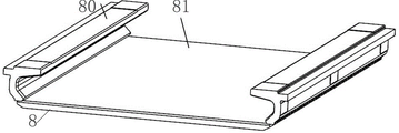
图1是C型槽结构示意图。Figure 1 is a schematic diagram of the structure of the C-shaped groove.
图2是 C型槽拼装工装爆炸示意图。Figure 2 is a schematic diagram of the explosion of the C-slot assembly tooling.
图3是C型槽拼装工装定位槽帮沿的示意图。Figure 3 is a schematic diagram of the edge of the positioning groove of the C-shaped groove assembly tool.
图4是图3中定位中板状态示意图。FIG. 4 is a schematic diagram of the state of the positioning middle plate in FIG. 3 .
图5是长度定位块中内侧宽度定位板打开状态示意图。Fig. 5 is a schematic diagram of the open state of the inner width positioning plate in the length positioning block.
图6是图5中内侧宽度定位板定位状态示意图。FIG. 6 is a schematic diagram of the positioning state of the inner width positioning plate in FIG. 5 .
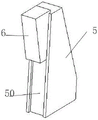
图7是外侧宽度定位板和宽度限位楔块放大视图。Figure 7 is an enlarged view of the outer width positioning plate and the width limiting wedge.
其中,1是架体、2是垫板、3是长度定位块、30是长度定位面、32是定位凸台、33是凸台定位面、4是内侧宽度定位板、40是内档宽度定位面、41是缺口定位面、5是外侧宽度定位板、50是滑槽、6是宽度限位楔块、7是楔帽销、8是C型槽、80是槽帮沿、81是中板。Among them, 1 is the frame body, 2 is the backing plate, 3 is the length positioning block, 30 is the length positioning surface, 32 is the positioning boss, 33 is the boss positioning surface, 4 is the inner width positioning plate, and 40 is the inner width positioning Surface, 41 is the notch positioning surface, 5 is the outer width positioning plate, 50 is the chute, 6 is the width limit wedge, 7 is the wedge cap pin, 8 is the C-shaped groove, 80 is the groove edge, 81 is the middle plate .
具体实施方式Detailed ways
以下将结合附图以及具体实施例,对本发明的技术方案进行清楚、完整的描述,应当理解,此处所描述的优选实施例仅用于说明和解释本发明,不能理解为对本发明保护范围的限制,该领域的技术熟练人员可以根据上述本发明的内容做出一些非本质的改进和调整。在本发明中,除非另有明确的规定和限定,本申请使用的技术术语应当为本发明所述技术人员所理解的通常意义。术语“相连”“连接”“固定”“设置”等应做广义理解,可以是固定连接,也可以是可拆卸连接,或成一体;可以是直接相连,也可以通过中间媒介间接相连;可以是机械连接、也可以是电连接。除非另有明确的限定。对于本领域的普通技术人员而言,可以根据具体情况理解上述术语在本发明中的具体含义。The technical solutions of the present invention will be clearly and completely described below with reference to the accompanying drawings and specific embodiments. It should be understood that the preferred embodiments described herein are only used to illustrate and explain the present invention, and should not be construed as limiting the protection scope of the present invention. , those skilled in the art can make some non-essential improvements and adjustments according to the above content of the present invention. In the present invention, unless otherwise expressly specified and limited, the technical terms used in the present application shall have the usual meanings understood by those skilled in the present invention. The terms "connected", "connected", "fixed", "arranged", etc. should be understood in a broad sense, and may be a fixed connection, a detachable connection, or an integrated body; it may be directly connected or indirectly connected through an intermediate medium; it may be The mechanical connection may also be an electrical connection. unless otherwise expressly qualified. For those of ordinary skill in the art, the specific meanings of the above terms in the present invention can be understood according to specific situations.
除非另有明确的规定和限定,第一特征在第二特征“上”或“下”可以是第一和第二特征直接接触,或第一和第二特征通过中间媒介间接接触。而且,第一特征在第二特征“之上”或者“上方”或者“上面”等可是第一特征在第二特征正上方或斜上方,或仅仅表示第一特征水平高度高于第二特征。第一特征在第二特征“之下”或“下方”或“下面”可以是第一特征在第二特征正下方或斜下方,或仅仅表示第一特征水平高度小于第二特征。诸如第一、第二等之类的关系术语仅仅用来将一个实体或者操作与另外一个实体或者操作区分开来,而不一定要求或者暗示这些实体或操作之间存在任何这种实际的关系或者顺序。应注意到:相似的标号和字母在下面的附图中表示类似项,因此,一旦某一项在一个附图中被定义,则在随后的附图中不需要对其进行进一步定义和解释。Unless expressly stated and defined otherwise, a first feature "on" or "under" a second feature may be in direct contact with the first and second features, or in indirect contact with the first and second features through an intermediary. Also, the first feature being "above" or "over" or "above" the second feature may mean that the first feature is directly above or obliquely above the second feature, or simply means that the first feature is level higher than the second feature. A first feature being "below" or "below" or "under" a second feature may mean that the first feature is directly or obliquely below the second feature, or simply means that the first feature has a lower level than the second feature. Relational terms such as first, second, etc. are only used to distinguish one entity or operation from another, and do not necessarily require or imply the existence of any such actual relationship or order. It should be noted that like numerals and letters refer to like items in the following figures, so once an item is defined in one figure, it does not require further definition and explanation in subsequent figures.
如图1-7所示,一种C型槽拼装工装,包括架体1,架体1包括定位C型槽8的两个槽帮沿80的上表面的定位平面。所述架体1上设置四个长度定位块3,四个长度定位块3分别位于一个矩形的四角附近位置,所述矩形的长边与C形槽8上两个槽帮沿80的上表面的长度方向外侧边线对应;每个长度定位块3包括一个长度定位面30,位于所述矩形的长度方向的两个相邻的长度定位块3的长度定位面30相向设置而且两个长度定位面30之间的最短距离与槽帮沿80的长度对应;位于所述矩形的宽度方向的两个相邻的长度定位块3的长度定位面在一个平面上。所述长度定位块3上设置限制槽帮沿80向内移动的内侧宽度定位板4,所述内侧宽度定位板4上设置与所述槽帮沿80的内表面接触的内档宽度定位面40。位于所述矩形宽度方向上相邻的两个内档宽度定位面40之间的最小距离与对应高度下C型槽8的两个槽帮沿80内表面之间的最小距离对应;所述矩形的两个长边的外侧分别设置至少一个限制槽帮沿80向外移动的外侧宽度定位板5。C型槽8的槽帮沿80上表面指槽帮沿80远离中板81的一端的外表面;槽帮沿80的内表面是指向着C型槽8内部的表面,槽帮沿80的外侧面是指远离C型槽8内部的表面。槽帮沿80的内档宽度是指C型槽8的两个槽帮沿80内表面之间距离,因为槽帮沿80内表面不是平面,不同的高度处,内档宽度不同。使用四个长度定位块3的长度定位面30定位两个槽帮沿80长度方向的位置并限制其移动;使用内侧宽度定位板4和外侧宽度定位板5对两槽帮沿80的宽度方向进行定位并限制其移动。限位结构简单,并且可以重复。长度定位块3和外侧宽度定位板5可以通过焊接或者螺栓固定等方式设置在架体上。C型槽8通过拼装工装定位,无需划对正线,减少拼装时间,提高拼装效率;拼装不需要测量,拼装尺寸精度更高。通过拼装工装固定,不需要点焊,保护拼装平台。As shown in FIGS. 1-7 , a C-shaped groove assembly tool includes a
所述内侧宽度定位板4转动设置在长度定位块3上,长度定位块3上设置定位凸台32,长度定位块3上还设置可拆卸的压紧定位块;内侧宽度定位板4转动到与定位凸台32接触时不能再转动,压紧定位块从与定位凸台32相对的方向压紧内侧宽度定位板4。即内侧宽度带定位板4转动到与定位凸台32接触时,压紧定位块和定位凸台32分别位于内侧宽度定位板4的两侧。所述内侧宽度定位板4通过第一销轴转动设置在长度定位块3上表面,长度定位块3上设置与第一销轴对应的销孔。定位凸台32可以是设置在长度定位块3上表面的矩形块,定位凸台32上设置凸台定位面33,内侧宽度定位板4上也可以设置与定位凸台32对应的矩形缺口,矩形缺口的侧面是与凸台定位面33接触定位的缺口定位面41,缺口定位面41与凸台定位面33压紧时,内侧宽度定位板4上内档宽度定位面40位于标准的位置。内档宽度定位面40可以和缺口定位面41是同一个平面、也可以是不同的平面,只要能满足准确定位功能即可。The inner
所述压紧定位块是楔帽销7,楔帽销7下部为销轴,上部是头端楔形块或者倒圆锥体;长度定位块3上设置与楔帽销7的销轴部分对应的销孔;楔帽销7向下移动,头部楔形块或者倒圆锥体压紧内侧宽度定位板4。楔帽销7的安装和取出非常方便,压紧的效果也很好。当然,压机定位块也可以是凸轮,凸轮的凸轮轴转动设置在长度定位块上与凸轮轴对应的轴孔内,凸轮转动可以压紧内侧宽度定位板4。The compression positioning block is a
内侧宽度定位板4有两种状态,一种为打开状态,取出楔帽销7,转动内侧宽度定位板4到图5中位置,此时可以取出或者放置槽帮沿80。当槽帮沿80放置后,旋转内侧宽度定位板4至图6中位置,长度定位块3的定位凸台32的凸台定位面33与内侧宽度定位板4的缺口定位面41配合定位,再插入楔帽销7限位,用内侧宽度定位板4限定出槽帮沿80的内档宽度。The inner
所述外侧宽度定位板5朝向所述矩形长边的表面与所述矩形长边之间间隔一定距离,外侧宽度定位板5和所述槽帮沿80之间设置宽度限位楔块6;宽度限位楔块6上端宽度大于下端宽度,向下移动宽度限位楔块6从槽帮沿80外侧对槽帮沿80限位。There is a certain distance between the surface of the outer
所述外侧宽度定位板5朝向所述矩形长边的一侧设置滑槽50;所述宽度限位楔块6在滑槽50内滑动。宽度限位楔块6可以是倒立的直角梯形,垂直的一侧腰在滑槽50内滑动,另一倾斜的腰与槽帮沿80外表面压紧限位。滑槽50结构可以防止宽度限位楔块6在移动过程中位置发生偏移。A
所述内侧宽度定位板4可拆卸设置在长度定位块3。可以通过螺栓等固定方式将内侧宽度定位板4固定在长度定位块3上。槽帮沿80安置在长度定位块3之间后,将内侧宽度定位板4固定在长度定位块3上。The inner
所述架体1上设置两个长度方向不互相垂直或者重合的垫板2,两个垫板2的上表面构成定位平面。定位平面可以是架体1的上表面,在拼装过程中,定位表面需要一定的精度、比如表面粗糙度以及平面度等才能保证拼装精度以及拼装后的C形槽的尺寸。如果整个架体1上表面都加工成同样的精度,会增加加工成本。所以在架体1上设置两个垫板2,两个垫板2上表面构成槽帮沿80上表面的定位平面。在加工时,只需要加工垫板2上表面到需要的精度即可,需要加工的表面减小,可以有效的降低的加工成本。优选所述两个垫板2平行设置,垫板2的长度方向与槽帮沿80的长度方向垂直;垫板2形状为长条形。The
具体实施过程:C型槽拼装工装拼装的过程:Specific implementation process: The process of C-shaped groove assembly tooling assembly:
(1)拼装时将槽帮沿80放置在架体1的垫板2上居中放置,并与垫板2垂直。(1) When assembling, place the
(2)根据槽帮沿80高度及宽度调整长度定位块3和外侧宽度定位板5至合适位置,通过焊接或螺栓连接使长度限位块3和外侧宽度定位板5固定在架体1上。其中外侧宽度定位板5与槽帮沿80保持一定距离,用于宽度限位楔块6后期的楔入。(2) Adjust the
(3)槽帮沿80长度方向两端面分别靠紧两端的长度定位块3,完成长度方向定位。此时长度定位块3上的内侧宽度定位板4一直处于打开状态。(3) The two end faces of the groove along the length direction of 80 are respectively abutted against the length positioning blocks 3 at both ends to complete the length direction positioning. At this time, the inner
(4) 旋转闭合内侧宽度定位板4,使之处于闭合状态,插入楔帽销7,使内侧宽度定位板4固定。(4) Rotate and close the inner
(5)使槽帮沿80内档面贴紧内侧宽度定位板4,将宽度限位楔块6向下楔入槽帮沿80与外侧宽度定位板5之间,完成槽帮沿80宽度方向的定位。(5) Make the inner surface of the
(6)槽帮沿80整体固定完成后,将中板81盖在槽帮沿80上,调整使中板80与槽帮沿端面对齐,两侧搭接均匀,然后定位焊中板81和槽帮沿80。(6) After the overall fixing of the
(7)定位焊完成后,在槽帮沿80下面靠近两端处搭焊拉筋,C型槽8拼焊完成。(7) After the tack welding is completed, the ties are lap welded under the
(8)取出宽度限位楔块6和楔帽销7,旋转内侧宽度定位板4,使其处于打开状态,取出C型槽8。(8) Take out the
本发明的C型槽的拼装通过拼装工装进行,不需要重复划对正线和点焊固定,提高拼装效率;C型槽固定和移出时不再需要焊接和火割,保护拼装平台;C型槽的拼装定位尺寸通过拼装工装确定,不再需要由人工测量确定,减少拼装误差。The assembling of the C-shaped groove of the present invention is carried out by assembling tooling, and there is no need to repeat the alignment and spot welding fixing, thereby improving the assembling efficiency; the C-shaped groove does not need welding and fire cutting when it is fixed and removed, and the assembling platform is protected; the C-shaped groove is fixed and removed. The assembly positioning size of the groove is determined by the assembly tooling, which no longer needs to be determined by manual measurement, thereby reducing assembly errors.
需要说明的是,描述中使用的术语比如“中心”“横向”“纵向”“长度”“宽度”“厚度”“高度”“前”“后”“左”“右”“上”“下”“竖直”“水平”“顶”“底”“内”“外”“轴向”“径向”“周向”“顺时针”“逆时针”等指示的方位或位置关系为基于附图所示的方位或位置关系,仅是为了便于描述本发明和简化描述,而不是指示或者暗示所指的装置或者原件必须具有特定的方位、以特定的方位构造和操作。因此不能理解为对本发明保护范围的限制。It should be noted that terms used in the description such as "center", "horizontal", "longitudinal", "length", "width", "thickness", "height", "front", "rear", "left", "right", "top", "bottom" "Vertical", "horizontal", "top", "bottom", "inner", "outer", "axial", "radial", "circumferential", "clockwise", "counterclockwise", etc. indicate the orientation or positional relationship based on the drawings The orientations or positional relationships shown are for convenience in describing the present invention and to simplify the description, and do not indicate or imply that the device or element referred to must have a particular orientation, be constructed and operate in a particular orientation. Therefore, it should not be construed as limiting the protection scope of the present invention.
以上所述的仅是本发明的优选实施方式,而不是全部的实施方式,本发明的保护范围并不局限于此。以上所述实施例的各技术特征可以进行任意的组合,为使描述简洁,未对上述实施例中的各个技术特征所有可能的组合都进行描述,然而,只要这些技术特征的组合不存在矛盾,都应当认为是本说明书记载的范围。当技术方案的结合出现相互矛盾或无法实现时应当认为这种技术方案的结合不存在,也不在本发明要求的保护范围之内。应当指出,对于本领域的及任何熟悉本技术领域的技术人员来说,在不脱离本发明整体构思和本发明的原理的精神的前提下,根据本发明的技术方案及其发明构思加以等同替换或改变,及作出的若干改变和改进,这些也应该视为本发明的保护范围。The above descriptions are only the preferred embodiments of the present invention, rather than all the embodiments, and the protection scope of the present invention is not limited thereto. The technical features of the above-described embodiments can be combined arbitrarily. For the sake of brevity, all possible combinations of the technical features in the above-described embodiments are not described. However, as long as there is no contradiction between the combinations of these technical features, All should be regarded as the scope described in this specification. When the combination of technical solutions contradicts each other or cannot be realized, it should be considered that such combination of technical solutions does not exist and is not within the protection scope of the present invention. It should be pointed out that for those skilled in the art and those skilled in the art, without departing from the overall concept of the present invention and the spirit of the principle of the present invention, equivalent replacements are made according to the technical solutions of the present invention and its inventive concept Or changes, and some changes and improvements made, these should also be regarded as the protection scope of the present invention.
Claims (8)
- Frock is assembled to C type groove, its characterized in that: the frame body comprises a positioning plane for positioning the upper surfaces of two ledge edges of the C-shaped groove; the frame body is provided with four length positioning blocks which are respectively positioned near four corners of a rectangle, and the long side of the rectangle corresponds to the outer side line in the length direction of the upper surface of the two ledge edges on the C-shaped groove; each length positioning block comprises a length positioning surface, two adjacent length positioning surfaces positioned in the length direction of the rectangle are oppositely arranged, and the shortest distance between the two length positioning surfaces corresponds to the length of the ledge edge; two adjacent length positioning surfaces in the width direction of the rectangle are on the same plane; the length positioning block is provided with an inner side width positioning plate for limiting the inward movement of the ledge edge, and the inner side width positioning plate is provided with an inner gear width positioning surface which is in contact with the inner surface of the ledge edge; the minimum distance between two adjacent inner gear width positioning surfaces in the rectangular width direction corresponds to the minimum distance between the inner surfaces of the two ledge edges of the lower C-shaped groove with the corresponding height; and the outer sides of the two long sides of the rectangle are respectively provided with at least one outer side width positioning plate for limiting the ledge to move outwards.
- 2. The frock is assembled to C type groove of claim 1, characterized in that: the inner side width positioning plate is rotatably arranged on the length positioning block, the length positioning block is provided with a positioning boss, and the length positioning block is also provided with a detachable pressing positioning block; the inner side width positioning plate can not rotate when rotating to be in contact with the positioning boss, and the pressing positioning block presses the inner side width positioning plate from the direction opposite to the positioning boss.
- 3. The frock is assembled to C type groove of claim 2, characterized in that: the pressing positioning block is a wedge cap pin, the lower part of the wedge cap pin is a pin shaft, and the upper part of the wedge cap pin is a head end wedge-shaped block or an inverted cone; the length positioning block is provided with a pin hole corresponding to the pin shaft part of the wedge cap pin; the wedge cap pin moves downwards, and the wedge block or the inverted cone at the head part compresses the inner side width positioning plate.
- 4. The frock is assembled to C type groove of claim 1, characterized in that: the surface of the outer side width positioning plate facing the long side of the rectangle is spaced from the long side of the rectangle by a certain distance, and a width limiting wedge block is arranged between the outer side width positioning plate and the ledge edge; the width of the upper end of the width limiting wedge block is larger than that of the lower end of the width limiting wedge block, and the width limiting wedge block is moved downwards to limit the ledge edge from the outer side of the ledge edge.
- 5. Frock is assembled to C type groove of claim 4, its characterized in that: a sliding groove is formed in one side, facing the long side of the rectangle, of the outer side width positioning plate; the width limiting wedge block slides in the sliding groove.
- 6. The frock is assembled to C-shaped groove of claim 1, characterized in that: the inner side width positioning plate is detachably arranged on the length positioning block.
- 7. The frock is assembled to C-shaped groove according to any one of claims 1-6, characterized in that: the frame body is provided with two backing plates with length directions which are not mutually vertical or overlapped, and the upper surfaces of the two backing plates form a positioning plane.
- 8. The frock is assembled to C type groove of claim 7, characterized in that: the two base plates are arranged in parallel, and the length direction of the base plates is vertical to the length direction of the ledge edge; the backing plate is in a strip shape.
Priority Applications (1)
| Application Number | Priority Date | Filing Date | Title |
|---|---|---|---|
| CN202011337208.4A CN114535896B (en) | 2020-11-25 | 2020-11-25 | C-slot assembly tooling |
Applications Claiming Priority (1)
| Application Number | Priority Date | Filing Date | Title |
|---|---|---|---|
| CN202011337208.4A CN114535896B (en) | 2020-11-25 | 2020-11-25 | C-slot assembly tooling |
Publications (2)
| Publication Number | Publication Date |
|---|---|
| CN114535896A true CN114535896A (en) | 2022-05-27 |
| CN114535896B CN114535896B (en) | 2025-04-11 |
Family
ID=81659629
Family Applications (1)
| Application Number | Title | Priority Date | Filing Date |
|---|---|---|---|
| CN202011337208.4A Active CN114535896B (en) | 2020-11-25 | 2020-11-25 | C-slot assembly tooling |
Country Status (1)
| Country | Link |
|---|---|
| CN (1) | CN114535896B (en) |
Citations (10)
| Publication number | Priority date | Publication date | Assignee | Title |
|---|---|---|---|---|
| CN205342307U (en) * | 2016-01-14 | 2016-06-29 | 山西阳煤广瑞达机械制造有限公司 | Device is decorated in middle part groove |
| CN205520196U (en) * | 2016-01-24 | 2016-08-31 | 湖南煤矿机械有限公司 | Construction installation equipment is closed to middle part bank of cells |
| CN107538127A (en) * | 2016-06-23 | 2018-01-05 | 陕西飞机工业(集团)有限公司 | A kind of method on benchmark fast positioning |
| CN207104396U (en) * | 2017-07-18 | 2018-03-16 | 山西煤矿机械制造股份有限公司 | A kind of extension type intermediate channel auxiliary machining device |
| CN209736898U (en) * | 2018-12-11 | 2019-12-06 | 斯图加特航空自动化(青岛)有限公司 | middle part groove is to frock |
| WO2020097696A1 (en) * | 2018-11-16 | 2020-05-22 | Ultimate Housing Solutions Pty Ltd | Modular walling system, components and methods |
| CN210936544U (en) * | 2019-11-07 | 2020-07-07 | 南京晫瑞机械科技有限公司 | A device for shaping the evaporator |
| CN211052968U (en) * | 2019-10-31 | 2020-07-21 | 佛山市固高自动化技术有限公司 | Positioning mechanism for baffle ledge, shovel board ledge, middle board and bottom board in middle trough |
| CN211165296U (en) * | 2019-09-29 | 2020-08-04 | 安徽千鑫通讯科技有限公司 | Universal die for shaping jig |
| CN214185892U (en) * | 2020-11-25 | 2021-09-14 | 郑州煤机长壁机械有限公司 | C-slot assembly tooling |
-
2020
- 2020-11-25 CN CN202011337208.4A patent/CN114535896B/en active Active
Patent Citations (10)
| Publication number | Priority date | Publication date | Assignee | Title |
|---|---|---|---|---|
| CN205342307U (en) * | 2016-01-14 | 2016-06-29 | 山西阳煤广瑞达机械制造有限公司 | Device is decorated in middle part groove |
| CN205520196U (en) * | 2016-01-24 | 2016-08-31 | 湖南煤矿机械有限公司 | Construction installation equipment is closed to middle part bank of cells |
| CN107538127A (en) * | 2016-06-23 | 2018-01-05 | 陕西飞机工业(集团)有限公司 | A kind of method on benchmark fast positioning |
| CN207104396U (en) * | 2017-07-18 | 2018-03-16 | 山西煤矿机械制造股份有限公司 | A kind of extension type intermediate channel auxiliary machining device |
| WO2020097696A1 (en) * | 2018-11-16 | 2020-05-22 | Ultimate Housing Solutions Pty Ltd | Modular walling system, components and methods |
| CN209736898U (en) * | 2018-12-11 | 2019-12-06 | 斯图加特航空自动化(青岛)有限公司 | middle part groove is to frock |
| CN211165296U (en) * | 2019-09-29 | 2020-08-04 | 安徽千鑫通讯科技有限公司 | Universal die for shaping jig |
| CN211052968U (en) * | 2019-10-31 | 2020-07-21 | 佛山市固高自动化技术有限公司 | Positioning mechanism for baffle ledge, shovel board ledge, middle board and bottom board in middle trough |
| CN210936544U (en) * | 2019-11-07 | 2020-07-07 | 南京晫瑞机械科技有限公司 | A device for shaping the evaporator |
| CN214185892U (en) * | 2020-11-25 | 2021-09-14 | 郑州煤机长壁机械有限公司 | C-slot assembly tooling |
Also Published As
| Publication number | Publication date |
|---|---|
| CN114535896B (en) | 2025-04-11 |
Similar Documents
| Publication | Publication Date | Title |
|---|---|---|
| CN202255185U (en) | Acceptance testing device for automobile glass guide rail | |
| CN102284900B (en) | A horizontal double-end grinding machine | |
| CN214185892U (en) | C-slot assembly tooling | |
| CN206869486U (en) | A kind of quick shifting type processing jig | |
| CN103084772A (en) | Frame assembly welding tool | |
| CN114535896B (en) | C-slot assembly tooling | |
| CN106270763B (en) | A kind of pattern blocks of tire mold blanking cutting method | |
| CN209624649U (en) | An automatic press-fit test seat | |
| CN220783051U (en) | Novel spiral retainer ring milling fixture | |
| CN209477407U (en) | A kind of cone mold for shearing machine | |
| CN217669001U (en) | Tool equipment | |
| CN205111181U (en) | Base welding jig | |
| CN102506188B (en) | Interchangeable processing technology for sealing surfaces of shutter and valve body | |
| CN217992153U (en) | Grinding tool for exhaust manifold flange | |
| CN110906839A (en) | An inspection tool for inspecting the welded parts of the front beam of the car roof | |
| CN211804617U (en) | A rotatable welding tool for the end plate bracket of a motor car | |
| CN115945724A (en) | Tunnel segment socket joint formula longitudinal joint connecting piece mills centre gripping tool | |
| CN210011529U (en) | Integrated four-station four-side edge-leaning center positioning fixture | |
| CN210549639U (en) | Milling machine fixture for milling | |
| CN112872681A (en) | Automobile welding body fixing device | |
| CN110203712B (en) | Welding type roller arm and welding positioning tool thereof | |
| CN222986063U (en) | A welding tool for the rubber strip groove in the middle seam of a door leaf | |
| CN208872268U (en) | A kind of device for the detection of punch elements surface planarity | |
| CN207464747U (en) | A kind of connecting rod milling face fixture | |
| CN212044374U (en) | Product bonding flip tooling |
Legal Events
| Date | Code | Title | Description |
|---|---|---|---|
| PB01 | Publication | ||
| PB01 | Publication | ||
| SE01 | Entry into force of request for substantive examination | ||
| SE01 | Entry into force of request for substantive examination | ||
| GR01 | Patent grant | ||
| GR01 | Patent grant |