CN114535531B - Automobile engine end cover die-casting device and method - Google Patents
Automobile engine end cover die-casting device and method Download PDFInfo
- Publication number
- CN114535531B CN114535531B CN202210163342.XA CN202210163342A CN114535531B CN 114535531 B CN114535531 B CN 114535531B CN 202210163342 A CN202210163342 A CN 202210163342A CN 114535531 B CN114535531 B CN 114535531B
- Authority
- CN
- China
- Prior art keywords
- die
- casting
- fixedly connected
- wall
- workbench
- Prior art date
- Legal status (The legal status is an assumption and is not a legal conclusion. Google has not performed a legal analysis and makes no representation as to the accuracy of the status listed.)
- Active
Links
Images



Classifications
-
- B—PERFORMING OPERATIONS; TRANSPORTING
- B22—CASTING; POWDER METALLURGY
- B22D—CASTING OF METALS; CASTING OF OTHER SUBSTANCES BY THE SAME PROCESSES OR DEVICES
- B22D17/00—Pressure die casting or injection die casting, i.e. casting in which the metal is forced into a mould under high pressure
- B22D17/08—Cold chamber machines, i.e. with unheated press chamber into which molten metal is ladled
- B22D17/12—Cold chamber machines, i.e. with unheated press chamber into which molten metal is ladled with vertical press motion
-
- B—PERFORMING OPERATIONS; TRANSPORTING
- B22—CASTING; POWDER METALLURGY
- B22D—CASTING OF METALS; CASTING OF OTHER SUBSTANCES BY THE SAME PROCESSES OR DEVICES
- B22D17/00—Pressure die casting or injection die casting, i.e. casting in which the metal is forced into a mould under high pressure
- B22D17/20—Accessories: Details
- B22D17/22—Dies; Die plates; Die supports; Cooling equipment for dies; Accessories for loosening and ejecting castings from dies
- B22D17/2218—Cooling or heating equipment for dies
-
- B—PERFORMING OPERATIONS; TRANSPORTING
- B22—CASTING; POWDER METALLURGY
- B22D—CASTING OF METALS; CASTING OF OTHER SUBSTANCES BY THE SAME PROCESSES OR DEVICES
- B22D17/00—Pressure die casting or injection die casting, i.e. casting in which the metal is forced into a mould under high pressure
- B22D17/20—Accessories: Details
- B22D17/22—Dies; Die plates; Die supports; Cooling equipment for dies; Accessories for loosening and ejecting castings from dies
- B22D17/2236—Equipment for loosening or ejecting castings from dies
Landscapes
- Engineering & Computer Science (AREA)
- Mechanical Engineering (AREA)
- Molds, Cores, And Manufacturing Methods Thereof (AREA)
Abstract
本发明公开了一种汽车发动机端盖压铸装置与方法,涉及压铸技术领域,本发明包括:工作台,压铸机构;抽气机构;冷却组件;推送机构;本发明在进行压铸操作时,通过向压铸槽内加入高温液体金属,液体金属将会产生大量热气体,使得抽气机构进行工作,抽气机构的工作将液体金属产生的热气体排出,并且抽气机构的工作还会带动冷却组件进行工作,使得冷却组件对所压铸的端盖进行快速有效的散热,并且吸收热量的冷却水将会为推送机构的工作提供动力,保证了端盖的压铸效率,节约了资源,保证了端盖压铸的质量,减轻了人员的负担,防止在取出端盖时,端盖并为进行良好散热,对人员带来伤害,对人员进行了一定程度的保护,方便人员使用。

The invention discloses a die-casting device and method for an end cover of an automobile engine, and relates to the technical field of die-casting. The invention includes: a workbench, a die-casting mechanism; an air pumping mechanism; a cooling assembly; Add high-temperature liquid metal into the die-casting tank, the liquid metal will generate a large amount of hot gas, which will make the pumping mechanism work, the work of the pumping mechanism will discharge the hot gas generated by the liquid metal, and the work of the pumping mechanism will also drive the cooling components Work, so that the cooling assembly can quickly and effectively dissipate heat from the die-cast end cap, and the cooling water that absorbs heat will provide power for the work of the push mechanism, ensuring the die-casting efficiency of the end cap, saving resources, and ensuring the die-casting of the end cap The high quality reduces the burden on personnel, prevents the end cover from harming personnel for good heat dissipation when the end cover is taken out, and provides a certain degree of protection for personnel, which is convenient for personnel to use.
Description
技术领域technical field
本发明涉及压铸技术领域,尤其涉及一种汽车发动机端盖压铸装置与方法。The invention relates to the field of die-casting technology, in particular to a die-casting device and method for an end cover of an automobile engine.
背景技术Background technique
压铸是一种金属铸造工艺,其特点是利用模具内腔对融化的金属施加高压。模具通常是用强度更高的合金加工而成的,这个过程有些类似注塑成型。大多数压铸铸件都是不含铁的,例如锌、铜、铝、镁、铅、锡以及铅锡合金以及它们的合金。根据压铸类型的不同,需要使用冷室压铸机或者热室压铸机。铸造设备和模具的造价高昂,因此压铸工艺一般只会用于批量制造大量产品。制造压铸的零部件相对来说比较容易,这一般只需要四个主要步骤,单项成本增量很低。压铸特别适合制造大量的中小型铸件,因此压铸是各种铸造工艺中使用最广泛的一种。同其他铸造技术相比,压铸的表面更为平整,拥有更高的尺寸一致性。在传统压铸工艺的基础上诞生了几种改进型的工艺,包括减少铸造缺陷排除气孔的无孔压铸工艺。主要用于加工锌,可以减少废弃物增加成品率的直接注射工艺。Die casting is a metal casting process characterized by the application of high pressure to molten metal using the cavity of a mold. Molds are usually machined from stronger alloys, a process somewhat similar to injection molding. Most die castings are ferrous, such as zinc, copper, aluminum, magnesium, lead, tin, and lead-tin alloys and their alloys. Depending on the type of die casting, a cold chamber die casting machine or a hot chamber die casting machine is used. The cost of casting equipment and molds is high, so the die casting process is generally only used for mass production of a large number of products. Manufacturing die-cast parts is relatively easy, generally requiring only four major steps with low incremental cost per item. Die casting is especially suitable for manufacturing a large number of small and medium-sized castings, so die casting is the most widely used of various casting processes. Compared with other casting technologies, die casting has a flatter surface and higher dimensional consistency. On the basis of the traditional die-casting process, several improved processes have been born, including the non-porous die-casting process that reduces casting defects and eliminates pores. It is mainly used for zinc processing, which can reduce waste and increase yield by direct injection process.
现有的压铸装置,在进行压铸操作时,无法根据所压铸端盖的冷却时间对冷却水进行定时输送,这将会造成不必要的资源浪费,并且在压铸完成后,需要将模具完全拆开,才能取下发动机端盖,无法在端盖冷却完成后自动将端盖推出,并且在取出端盖时,无法保证所压铸端盖已经充分散热,对操作工的健康带来一定威胁,为此我们提出一种汽车发动机端盖压铸装置与方法来解决上述问题。The existing die-casting device cannot regularly deliver the cooling water according to the cooling time of the die-casting end cap during the die-casting operation, which will cause unnecessary waste of resources, and after the die-casting is completed, the mold needs to be completely disassembled , to remove the engine end cover, the end cover cannot be automatically pushed out after the end cover is cooled, and when the end cover is taken out, it cannot be guaranteed that the die-cast end cover has been fully dissipated, which poses a certain threat to the health of the operator. We propose a die-casting device and method for an automobile engine end cover to solve the above problems.
发明内容Contents of the invention
本发明的目的是为了解决现有技术中存在无法根据所压铸端盖的冷却时间对冷却水进行定时输送,这将会造成不必要的资源浪费,并且在压铸完成后,需要将模具完全拆开,才能取下发动机端盖,无法在端盖冷却完成后自动将端盖推出,并且在取出端盖时,无法保证所压铸端盖已经充分散热,对操作工的健康带来一定威胁的问题,而提出的一种汽车发动机端盖压铸装置与方法。The purpose of the present invention is to solve the problem in the prior art that the cooling water cannot be delivered regularly according to the cooling time of the die-casting end cap, which will cause unnecessary waste of resources, and after the die-casting is completed, the mold needs to be completely disassembled , to remove the engine end cover, the end cover cannot be automatically pushed out after the end cover is cooled, and when the end cover is taken out, it cannot be guaranteed that the die-cast end cover has been fully dissipated, which poses a certain threat to the health of the operator. A die-casting device and method for an automobile engine end cover is proposed.
为了实现上述目的,本发明采用了如下技术方案:In order to achieve the above object, the present invention adopts the following technical solutions:
一种汽车发动机端盖压铸装置,包括:A die-casting device for an automobile engine end cover, comprising:
工作台,所述工作台的底部固定连接有支腿,所述工作台的顶部固定连接有电动滑架,所述电动滑架的顶部固定连接有热熔箱,所述工作台的底部固定连接有水箱,所述热熔箱的底部安装有压铸机构,所述压铸机构用于进行压铸操作;A workbench, the bottom of the workbench is fixedly connected with outriggers, the top of the workbench is fixedly connected with an electric carriage, the top of the electric carriage is fixedly connected with a hot melting tank, and the bottom of the workbench is fixedly connected with There is a water tank, and a die-casting mechanism is installed at the bottom of the hot melt tank, and the die-casting mechanism is used for die-casting operation;
抽气机构,所述抽气机构安装在所述工作台以及压铸机构内,所述抽气机构用于在压铸时进行排气操作,并为该装置的工作提供部分动力,所述抽气机构包括抽气风扇、转轴、支架、皮带、抽气管和连接管;所述抽气风扇的内侧壁与所述转轴的外侧壁固定连接,所述支架的相向侧与所述转轴的端部固定连接,所述皮带的外侧壁与所述转轴的外侧壁相贴合,所述抽气管的内侧壁与所述支架的外侧壁固定连接,所述连接管的外侧壁与所述抽气管的端部内侧壁相适配;The air extraction mechanism is installed in the workbench and the die-casting mechanism. The air extraction mechanism is used for exhausting during die-casting and provides part of the power for the work of the device. The air extraction mechanism It includes an exhaust fan, a rotating shaft, a bracket, a belt, an exhaust pipe and a connecting pipe; the inner wall of the exhaust fan is fixedly connected to the outer wall of the rotating shaft, and the opposite side of the bracket is fixedly connected to the end of the rotating shaft , the outer wall of the belt is attached to the outer wall of the rotating shaft, the inner wall of the air extraction pipe is fixedly connected with the outer wall of the bracket, the outer wall of the connecting pipe is connected to the end of the air extraction pipe Compatible with the inner wall;
冷却组件,所述冷却组件安装在所述工作台上,所述冷却组件由所述抽气机构进行驱动,所述冷却组件用于对压铸的端盖进行冷却操作,所述冷却组件包括转杆、叶轮、进水管、水冷管和排水管;所述转杆的外侧壁与所述叶轮的内侧壁固定连接,所述进水管的内侧壁与所述转杆的端部转动连接,所述水冷管的端部与所述进水管的端部固定连接,所述排水管的顶部与所述水冷管的内侧壁顶部固定连接,所述抽气管安装在所述工作台内,所述皮带贯穿所述抽气管的侧壁并延伸至所述转杆的外侧壁,所述转杆的外侧壁与所述皮带的内侧壁相贴合,所述进水管的端部与所述工作台的外侧壁固定连接,所述排水管的底部与所述工作台的底部固定连接;a cooling assembly, the cooling assembly is installed on the workbench, the cooling assembly is driven by the air extraction mechanism, the cooling assembly is used for cooling the die-cast end cap, and the cooling assembly includes a rotating rod , an impeller, a water inlet pipe, a water cooling pipe and a drain pipe; the outer wall of the rotating rod is fixedly connected with the inner wall of the impeller, the inner wall of the water inlet pipe is rotationally connected with the end of the rotating rod, and the water cooling The end of the pipe is fixedly connected to the end of the water inlet pipe, the top of the drain pipe is fixedly connected to the top of the inner wall of the water cooling pipe, the exhaust pipe is installed in the workbench, and the belt runs through the The side wall of the suction pipe extends to the outer wall of the rotating rod, the outer wall of the rotating rod fits the inner wall of the belt, the end of the water inlet pipe and the outer wall of the workbench Fixedly connected, the bottom of the drainage pipe is fixedly connected with the bottom of the workbench;
推送机构,所述推送机构安装在所述水箱的内部,所述推送机构用于在压铸的端盖完全冷却后将端盖推出。A pushing mechanism, the pushing mechanism is installed inside the water tank, and the pushing mechanism is used to push out the end cap after the die-casting end cap is completely cooled.
优选地,所述压铸机构包括波纹管、电动滑板、溢流槽、压铸板和压铸槽;所述波纹管的底部与所述电动滑板的顶部固定连接,所述溢流槽开设在所述电动滑板的顶部,所述压铸板安装在所述电动滑板的底部,所述压铸槽正对所述压铸板的底部设置。Preferably, the die-casting mechanism includes a bellows, an electric skateboard, an overflow tank, a die-casting plate and a die-casting tank; the bottom of the bellows is fixedly connected to the top of the electric skateboard, and the overflow tank is opened on the electric The top of the skateboard, the die-casting plate is installed on the bottom of the electric skateboard, and the die-casting groove is set opposite to the bottom of the die-casting plate.
优选地,所述推送机构包括套筒、浮力球、推送弹簧、推送杆和推送板;所述套筒的内侧壁与所述浮力球的外侧壁滑动连接,所述浮力球的顶部与所述推送弹簧的底部固定连接,所述推送弹簧的顶部与所述推送杆的底部固定连接,所述推送杆的顶部与所述推送板的底部固定连接。Preferably, the push mechanism includes a sleeve, a buoyancy ball, a push spring, a push rod and a push plate; the inner side wall of the sleeve is slidably connected to the outer side wall of the buoyancy ball, and the top of the buoyancy ball is connected to the outer side wall of the buoyancy ball. The bottom of the push spring is fixedly connected, the top of the push spring is fixedly connected with the bottom of the push rod, and the top of the push rod is fixedly connected with the bottom of the push plate.
优选地,所述电动滑板的端部与所述电动滑架的相向侧滑动连接,所述压铸槽开设在所述工作台的顶部。Preferably, the end of the electric skateboard is slidably connected to the opposite side of the electric carriage, and the die-casting groove is opened on the top of the workbench.
优选地,所述连接管安装在所述压铸板上,所述水冷管正对所述压铸槽的底部设置。Preferably, the connecting pipe is installed on the die-casting plate, and the water-cooling pipe is arranged facing the bottom of the die-casting tank.
优选地,所述推送杆的外侧壁与所述工作台滑动连接,所述推送板的外侧壁与所述压铸槽的内侧壁相贴合,所述套筒的顶部与所述工作台的底部固定连接。Preferably, the outer wall of the push rod is slidably connected with the workbench, the outer wall of the push plate fits with the inner wall of the die-casting groove, and the top of the sleeve is in contact with the bottom of the workbench. Fixed connection.
一种采用汽车发动机端盖压铸装置的压铸方法,包括如下步骤:A die-casting method using an automobile engine end cover die-casting device, comprising the steps of:
在进行压铸操作时,首先启动电动滑架和电动滑板,使得电动滑板向下移动,直至压铸板的底部与压铸槽的顶部相贴合;When performing die-casting operation, first start the electric carriage and electric skateboard, so that the electric skateboard moves down until the bottom of the die-casting plate fits with the top of the die-casting tank;
然后向热熔箱内加入液体金属,直至液体金属通过溢流槽排出一定时间;Then add liquid metal into the hot melting tank until the liquid metal is discharged through the overflow tank for a certain period of time;
在压铸的过程中,液体金属产生的热蒸汽将会经过抽气机构排放,在排放的过程中,抽气机构将会带动冷却组件进行工作;During the die-casting process, the hot steam generated by the liquid metal will be discharged through the exhaust mechanism. During the discharge process, the exhaust mechanism will drive the cooling components to work;
冷却组件的工作将会使得外界冷却水对所压铸的端盖进行散热;The work of the cooling component will make the external cooling water dissipate heat to the die-cast end cover;
吸收热量后的冷却水将会进入水箱内,使得推送机构在冷却水的浮力作用下工作;The cooling water after absorbing the heat will enter the water tank, making the pushing mechanism work under the buoyancy of the cooling water;
当抽气机构不在工作时,冷却组件停止工作,此时启动电动滑架和电动滑板,直至电动滑板恢复到最初状态;When the air extraction mechanism is not working, the cooling assembly stops working, and at this time, start the electric carriage and electric skateboard until the electric skateboard returns to its original state;
在此过程中,通过推送机构的工作将会把冷却后的压铸端盖推送出压铸槽,便可取下所压铸的端盖完成整个压铸操作。During this process, the cooled die-casting end cap will be pushed out of the die-casting tank through the work of the pushing mechanism, and the die-casting end cap can be removed to complete the entire die-casting operation.
相比现有技术,本发明的有益效果为:Compared with the prior art, the beneficial effects of the present invention are:
1、本发明在进行压铸操作时,通过向压铸槽内加入高温液体金属,液体金属将会产生大量热气体,使得抽气机构进行工作,抽气机构的工作将液体金属产生的热气体排出,并且抽气机构的工作还会带动冷却组件进行工作,使得冷却组件对所压铸的端盖进行快速有效的散热,并且吸收热量的冷却水将会为推送机构的工作提供动力,保证了端盖的压铸效率,节约了资源,保证了端盖压铸的质量,减轻了人员的负担,防止在取出端盖时,端盖并为进行良好散热,对人员带来伤害,对人员进行了一定程度的保护,方便人员使用。1. When the present invention is performing die-casting operations, by adding high-temperature liquid metal into the die-casting tank, the liquid metal will generate a large amount of hot gas, so that the pumping mechanism will work, and the work of the pumping mechanism will discharge the hot gas generated by the liquid metal. And the work of the air extraction mechanism will also drive the cooling assembly to work, so that the cooling assembly can quickly and effectively dissipate heat from the die-cast end cover, and the cooling water that absorbs heat will provide power for the work of the pushing mechanism, ensuring the end cover. Die-casting efficiency saves resources, ensures the quality of the die-casting of the end cover, reduces the burden on personnel, prevents the end cover from harming personnel for good heat dissipation when the end cover is taken out, and protects personnel to a certain extent , convenient for personnel to use.
2、本发明在压铸的过程中,通过吸收热量的冷却水进入水箱内,使得推送机构在水的浮力作用下处于蓄能状态,当抽气机构不在工作时,此时冷区组件停止工作,然后便可启动电动滑架使得压铸机构工作,在压铸机构工作的过程中,由于推送机构在水的浮力作用下处于蓄能状态,此时压铸板无法对压铸端盖进行下压,使得推送机构开始工作,将所压铸的端盖推出压铸槽内,便于人员将压铸后的端盖取出。2. In the process of die-casting, the cooling water that absorbs heat enters the water tank, so that the pushing mechanism is in an energy storage state under the buoyancy of the water. When the air pumping mechanism is not working, the components in the cold zone stop working at this time. Then the electric carriage can be started to make the die-casting mechanism work. During the working process of the die-casting mechanism, because the push mechanism is in an energy storage state under the buoyancy of the water, the die-cast plate cannot press down the die-cast end cover at this time, so that the push mechanism Start to work, and push the die-cast end cap out of the die-casting groove, so that the personnel can take out the die-cast end cap conveniently.
附图说明Description of drawings
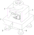
图1为本发明提出的一种汽车发动机端盖压铸装置与方法的三维立体结构示意图;Fig. 1 is the three-dimensional structural schematic diagram of a kind of automobile engine end cap die-casting device and method that the present invention proposes;
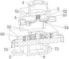
图2为本发明提出的一种汽车发动机端盖压铸装置与方法的三维立体正面剖视结构示意图;Fig. 2 is a three-dimensional front sectional structural schematic diagram of an automobile engine end cover die-casting device and method proposed by the present invention;
图3为本发明提出的一种汽车发动机端盖压铸装置与方法的三维立体顶部剖视结构示意图;Fig. 3 is a three-dimensional top sectional structural schematic diagram of an automobile engine end cover die-casting device and method proposed by the present invention;
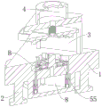
图4为本发明提出的一种汽车发动机端盖压铸装置与方法的三维立体斜面剖视结构示意图;Fig. 4 is a schematic diagram of a three-dimensional oblique cross-sectional structure of a die-casting device and method for an automobile engine end cover proposed by the present invention;
图5为本发明提出的一种汽车发动机端盖压铸装置与方法的抽气机构三维立体结构示意图;Fig. 5 is a schematic diagram of a three-dimensional structure of an air extraction mechanism of an automobile engine end cover die-casting device and method proposed by the present invention;
图6为本发明提出的一种汽车发动机端盖压铸装置与方法的推送机构三维立体结构示意图;Fig. 6 is a schematic diagram of a three-dimensional structure of a pushing mechanism of an automobile engine end cover die-casting device and method proposed by the present invention;
图7为本发明提出的一种汽车发动机端盖压铸装置与方法的图2中A处放大结构示意图;Fig. 7 is a kind of automobile engine end cover die-casting device and method that the present invention proposes the schematic diagram of enlarged structure of A place in Fig. 2;
图8为本发明提出的一种汽车发动机端盖压铸装置与方法的图4中B处放大结构示意图。FIG. 8 is a schematic diagram of an enlarged structure at B in FIG. 4 of an automobile engine end cover die-casting device and method proposed by the present invention.
图中:1、工作台;2、支腿;3、电动滑架;4、热熔箱;5、压铸机构;51、波纹管;52、电动滑板;53、溢流槽;54、压铸板;55、压铸槽;6、抽气机构;61、抽气风扇;62、转轴;63、支架;64、皮带;65、抽气管;66、连接管;7、冷却组件;71、转杆;72、叶轮;73、进水管;74、水冷管;75、排水管;8、水箱;9、推送机构;91、套筒;92、浮力球;93、推送弹簧;94、推送杆;95、推送板。In the figure: 1. Workbench; 2. Legs; 3. Electric carriage; 4. Hot melt box; 5. Die-casting mechanism; 51. Bellows; 52. Electric skateboard; 53. Overflow tank; 54. Die-casting plate ;55, die-casting tank; 6, exhaust mechanism; 61, exhaust fan; 62, rotating shaft; 63, bracket; 64, belt; 65, exhaust pipe; 66, connecting pipe; 7, cooling assembly; 71, rotating rod; 72, impeller; 73, water inlet pipe; 74, water cooling pipe; 75, drain pipe; 8, water tank; 9, push mechanism; 91, sleeve; 92, buoyancy ball; 93, push spring; 94, push rod; 95, push plate.
具体实施方式Detailed ways
下面将结合本发明实施例中的附图,对本发明实施例中的技术方案进行清楚、完整地描述,显然,所描述的实施例仅仅是本发明一部分实施例,而不是全部的实施例。The following will clearly and completely describe the technical solutions in the embodiments of the present invention with reference to the accompanying drawings in the embodiments of the present invention. Obviously, the described embodiments are only some, not all, embodiments of the present invention.
参照图1-8,一种汽车发动机端盖压铸装置,包括:Referring to Figures 1-8, a die-casting device for an automobile engine end cover, including:
工作台1,工作台1的底部固定连接有支腿2,工作台1的顶部固定连接有电动滑架3,电动滑架3的顶部固定连接有热熔箱4,工作台1的底部固定连接有水箱8,热熔箱4的底部安装有压铸机构5,压铸机构5用于进行压铸操作;
抽气机构6,抽气机构6安装在工作台1以及压铸机构5内,抽气机构6用于在压铸时进行排气操作,并为该装置的工作提供部分动力;Air extraction mechanism 6, the air extraction mechanism 6 is installed in the
冷却组件7,冷却组件7安装在工作台1上,冷却组件7由抽气机构6进行驱动,冷却组件7用于对压铸的端盖进行冷却操作;
推送机构9,推送机构9安装在水箱8的内部,推送机构9用于在压铸的端盖完全冷却后将端盖推出;Pushing
通过上述结构的设置,保证了端盖的压铸效率,节约了资源,保证了端盖压铸的质量,减轻了人员的负担,防止在取出端盖时,端盖并为进行良好散热,对人员带来伤害,对人员进行了一定程度的保护,便于人员将压铸后的端盖取出,方便人员使用。Through the setting of the above structure, the die-casting efficiency of the end cover is guaranteed, resources are saved, the quality of the die-casting of the end cover is guaranteed, the burden on the personnel is reduced, and the end cover is not taken out for good heat dissipation, which will bring harm to the personnel. In case of injury, personnel are protected to a certain extent, which is convenient for personnel to take out the end cover after die-casting and convenient for personnel to use.
其中,压铸机构5包括波纹管51、电动滑板52、溢流槽53、压铸板54和压铸槽55;波纹管51的底部与电动滑板52的顶部固定连接,溢流槽53开设在电动滑板52的顶部,压铸板54安装在电动滑板52的底部,压铸槽55正对压铸板54的底部设置;Wherein, die-
通过上述结构的设置,实现了对端盖的压铸操作,使得压铸的端盖能够符合生产标准。Through the setting of the above structure, the die-casting operation of the end cap is realized, so that the die-cast end cap can meet the production standard.
其中,抽气机构6包括抽气风扇61、转轴62、支架63、皮带64、抽气管65和连接管66;抽气风扇61的内侧壁与转轴62的外侧壁固定连接,支架63的相向侧与转轴62的端部固定连接,皮带64的外侧壁与转轴62的外侧壁相贴合,抽气管65的内侧壁与支架63的外侧壁固定连接,连接管66的外侧壁与抽气管65的端部内侧壁相适配;Wherein, the air extraction mechanism 6 comprises an
通过上述结构的设置,实现了对在压铸过程中产生的气体进行有效的排放,防止所压铸的发动机端盖内部存在气泡,使得生产后的发动机端盖无法达到要求,并且还为该装置的工作提供了部分动力,保证了该装置的稳定运行。Through the setting of the above structure, the gas generated in the die-casting process can be effectively discharged to prevent the air bubbles inside the die-casted engine end cover, so that the produced engine end cover cannot meet the requirements, and it is also for the work of the device. Part of the power is provided to ensure the stable operation of the device.
其中,冷却组件7包括转杆71、叶轮72、进水管73、水冷管74和排水管75;转杆71的外侧壁与叶轮72的内侧壁固定连接,进水管73的内侧壁与转杆71的端部转动连接,水冷管74的端部与进水管73的端部固定连接,排水管75的顶部与水冷管74的内侧壁顶部固定连接,水冷管74设置为“蚊香”型;Wherein, the cooling
通过上述结构的设置,能够对所压铸的端盖进行快速有效的散热,保证了端盖压铸的效率,并且为推送机构9的工作提供了动力支撑,通过“蚊香”型的水冷管74能够使得冷却水对所压铸的端盖进行充分的散热。Through the setting of the above structure, the die-cast end cap can be quickly and effectively dissipated heat, ensuring the efficiency of the die-casting of the end cap, and providing power support for the work of the pushing
其中,推送机构9包括套筒91、浮力球92、推送弹簧93、推送杆94和推送板95;套筒91的内侧壁与浮力球92的外侧壁滑动连接,浮力球92的顶部与推送弹簧93的底部固定连接,推送弹簧93的顶部与推送杆94的底部固定连接,推送杆94的顶部与推送板95的底部固定连接。Wherein,
其中,电动滑板52的端部与电动滑架3的相向侧滑动连接,压铸槽55开设在工作台1的顶部。Wherein, the end of the
其中,连接管66安装在压铸板54上,抽气管65安装在工作台1内,皮带64贯穿抽气管65的侧壁并延伸至转杆71的外侧壁。Wherein, the connecting
其中,转杆71的外侧壁与皮带64的内侧壁相贴合,水冷管74正对压铸槽55的底部设置,进水管73的端部与工作台1的外侧壁固定连接,排水管75的底部与工作台1的底部固定连接。Wherein, the outer wall of the
其中,推送杆94的外侧壁与工作台1滑动连接,推送板95的外侧壁与压铸槽55的内侧壁相贴合,套筒91的顶部与工作台1的底部固定连接。Wherein, the outer wall of the
一种采用汽车发动机端盖压铸装置的压铸方法,包括如下步骤:A die-casting method using an automobile engine end cover die-casting device, comprising the steps of:
在进行压铸操作时,首先启动电动滑架3和电动滑板52,使得电动滑板52向下移动,直至压铸板54的底部与压铸槽55的顶部相贴合;When carrying out the die-casting operation, first start the
然后向热熔箱4内加入液体金属,直至液体金属通过溢流槽53排出一定时间;Then add liquid metal in the
在压铸的过程中,液体金属产生的热蒸汽将会经过抽气机构6排放,在排放的过程中,抽气机构6将会带动冷却组件7进行工作;During the die-casting process, the hot steam generated by the liquid metal will be discharged through the exhaust mechanism 6, and during the discharge process, the exhaust mechanism 6 will drive the cooling
冷却组件7的工作将会使得外界冷却水对所压铸的端盖进行散热;The work of the cooling
吸收热量后的冷却水将会进入水箱8内,使得推送机构9在冷却水的浮力作用下工作;The cooling water after absorbing the heat will enter the
当抽气机构6不在工作时,冷却组件7停止工作,此时启动电动滑架3和电动滑板52,直至电动滑板52恢复到最初状态;When the pumping mechanism 6 was not working, the cooling
在此过程中,通过推送机构9的工作将会把冷却后的压铸端盖推送出压铸槽55,便可取下所压铸的端盖完成整个压铸操作。During this process, the cooled die-casting end cap will be pushed out of the die-casting
本发明中,使用时,启动电动滑架3使得电动滑板52沿电动滑架3向下滑动,直至压铸板54的底部与压铸槽55的顶部相贴合,便可关闭电动滑架3,然后便可向热熔箱4内加入高温液体金属,使得液体金属经过波纹管51进入压铸板54与压铸槽55所组成的空间内,直至溢流槽53内流出液体金属,便可停止加入液体金属;In the present invention, when in use, start the
在此过程中,通过高温液体金属的加入,将会使得压铸槽55与压铸板54所组成空间内的气体通过连接管66进入抽气管65内,然后经过抽气管65排出;During this process, through the addition of high-temperature liquid metal, the gas in the space formed by the die-casting
在排出的过程中将会带动抽气风扇61转动,使得转轴62带动皮带64转动,进而带动转杆71转动,使得叶轮72通过进水管73抽取冷却水进入水冷管74内,使得冷却水在“蚊香”型的水冷管74内对所压铸的端盖进行充分的散热,吸收热量的冷却水将会经过排水管75进入水箱8内;During the discharge process, the
通过水箱8内冷却水的持续增加,将会使得浮力球92在冷却水浮力作用下沿套筒91的内侧壁向上滑动,压缩推送弹簧93,使得推送机构9处于蓄能状态;Through the continuous increase of cooling water in the
当压铸槽55与压铸板54所组成空间内的气体完全排放时,抽气机构6将会停止工作,此时便可启动电动滑架3使得电动滑板52向上滑动直至滑动至最初位置,便可关闭电动滑架3;When the gas in the space formed by the die-casting
在此过程中,由于压铸板54无法挤压所压铸的端盖,以及推送机构9处于蓄能状态,在压铸板54向上移动的过程中,推送杆94和推送板95将会在推送弹簧93的作用下将所压铸的端盖向上推动,当推送弹簧93无法推送推送杆94和推送板95时,冷却水的浮力将会再次推动浮力球92向上移动,然后通过推送弹簧93、推送杆94和推送板95将所压铸的端盖推出,便可取下压铸后的端盖;During this process, since the die-casting
然后将水箱8内的水排出,再次使用时重复上述操作即可。Then the water in the
在本发明的描述中,需要理解的是,术语“中心”、“纵向”、“横向”、“长度”、“宽度”、“厚度”、“上”、“下”、“前”、“后”、“左”、“右”、“竖直”、“水平”、“顶”、“底”、“内”、“外”、“顺时针”、“逆时针”等指示的方位或位置关系为基于附图所示的方位或位置关系,仅是为了便于描述本发明和简化描述,而不是指示或暗示所指的设备或元件必须具有特定的方位、以特定的方位构造和操作,因此不能理解为对本发明的限制。In describing the present invention, it should be understood that the terms "center", "longitudinal", "transverse", "length", "width", "thickness", "upper", "lower", "front", " Orientation indicated by rear, left, right, vertical, horizontal, top, bottom, inside, outside, clockwise, counterclockwise, etc. The positional relationship is based on the orientation or positional relationship shown in the drawings, and is only for the convenience of describing the present invention and simplifying the description, rather than indicating or implying that the referred device or element must have a specific orientation, be constructed and operated in a specific orientation, Therefore, it should not be construed as limiting the invention.
此外,术语“第一”、“第二”仅用于描述目的,而不能理解为指示或暗示相对重要性或者隐含指明所指示的技术特征的数量。由此,限定有“第一”、“第二”的特征可以明示或者隐含地包括一个或者更多个该特征。在本发明的描述中,“多个”的含义是两个或两个以上,除非另有明确具体的限定。In addition, the terms "first" and "second" are used for descriptive purposes only, and cannot be interpreted as indicating or implying relative importance or implicitly specifying the quantity of indicated technical features. Thus, a feature defined as "first" and "second" may explicitly or implicitly include one or more of these features. In the description of the present invention, "plurality" means two or more, unless otherwise specifically defined.
以上所述,仅为本发明较佳的具体实施方式,但本发明的保护范围并不局限于此,任何熟悉本技术领域的技术人员在本发明揭露的技术范围内,根据本发明的技术方案及其发明构思加以等同替换或改变,都应涵盖在本发明的保护范围之内。The above is only a preferred embodiment of the present invention, but the scope of protection of the present invention is not limited thereto, any person familiar with the technical field within the technical scope disclosed in the present invention, according to the technical solution of the present invention Any equivalent replacement or change of the inventive concepts thereof shall fall within the protection scope of the present invention.
Claims (7)
Priority Applications (1)
| Application Number | Priority Date | Filing Date | Title |
|---|---|---|---|
| CN202210163342.XA CN114535531B (en) | 2022-02-22 | 2022-02-22 | Automobile engine end cover die-casting device and method |
Applications Claiming Priority (1)
| Application Number | Priority Date | Filing Date | Title |
|---|---|---|---|
| CN202210163342.XA CN114535531B (en) | 2022-02-22 | 2022-02-22 | Automobile engine end cover die-casting device and method |
Publications (2)
| Publication Number | Publication Date |
|---|---|
| CN114535531A CN114535531A (en) | 2022-05-27 |
| CN114535531B true CN114535531B (en) | 2023-03-21 |
Family
ID=81677212
Family Applications (1)
| Application Number | Title | Priority Date | Filing Date |
|---|---|---|---|
| CN202210163342.XA Active CN114535531B (en) | 2022-02-22 | 2022-02-22 | Automobile engine end cover die-casting device and method |
Country Status (1)
| Country | Link |
|---|---|
| CN (1) | CN114535531B (en) |
Families Citing this family (1)
| Publication number | Priority date | Publication date | Assignee | Title |
|---|---|---|---|---|
| CN114918404B (en) * | 2022-06-01 | 2023-03-28 | 中南大学 | Energy-saving and gas-saving device of die casting machine and using method thereof |
Citations (3)
| Publication number | Priority date | Publication date | Assignee | Title |
|---|---|---|---|---|
| CN112605367A (en) * | 2021-01-05 | 2021-04-06 | 于秀芹 | Micro-vacuum precision casting process |
| CN112909714A (en) * | 2021-01-14 | 2021-06-04 | 河池学院 | High-power adjustable pulse fiber laser |
| CN113286502A (en) * | 2021-06-11 | 2021-08-20 | 康亚周 | Automatically controlled cabinet of heat dissipation type for track traffic |
Family Cites Families (3)
| Publication number | Priority date | Publication date | Assignee | Title |
|---|---|---|---|---|
| CN103769560A (en) * | 2014-02-12 | 2014-05-07 | 宁波霍思特精密机械有限公司 | Suction casting process of turbocharger impeller |
| CN215638935U (en) * | 2021-05-28 | 2022-01-25 | 孝感金达钢铁有限公司 | Continuous casting billet sensible heat energy recycling device |
| CN114042891A (en) * | 2021-11-10 | 2022-02-15 | 王克亮 | Aluminum plate die-casting system and using method thereof |
-
2022
- 2022-02-22 CN CN202210163342.XA patent/CN114535531B/en active Active
Patent Citations (3)
| Publication number | Priority date | Publication date | Assignee | Title |
|---|---|---|---|---|
| CN112605367A (en) * | 2021-01-05 | 2021-04-06 | 于秀芹 | Micro-vacuum precision casting process |
| CN112909714A (en) * | 2021-01-14 | 2021-06-04 | 河池学院 | High-power adjustable pulse fiber laser |
| CN113286502A (en) * | 2021-06-11 | 2021-08-20 | 康亚周 | Automatically controlled cabinet of heat dissipation type for track traffic |
Also Published As
| Publication number | Publication date |
|---|---|
| CN114535531A (en) | 2022-05-27 |
Similar Documents
| Publication | Publication Date | Title |
|---|---|---|
| CN215657779U (en) | Molding motor shell casting die | |
| CN210475423U (en) | Metal casting equipment for aluminum alloy | |
| CN110696262B (en) | Thin wall multi-cavity mould rapid prototyping equipment | |
| CN114535531A (en) | Automobile engine end cover die-casting device and method | |
| CN112605363B (en) | Aluminum die-casting forming die with auxiliary pushing mechanism | |
| CN213496387U (en) | Auto parts die-casting equipment | |
| CN210253881U (en) | Cooling die frame for automobile die | |
| CN220574703U (en) | Die casting device for automobile part production | |
| CN220426777U (en) | Heat dissipation exhaust structure of die casting die | |
| CN218799001U (en) | Metal die casting equipment convenient to clearance | |
| CN214814652U (en) | Die casting device capable of realizing low-temperature cooling | |
| CN218168624U (en) | Make things convenient for mould for metal casting of whole feeding | |
| CN215508909U (en) | A new type of multi-functional aluminum heat sink die-casting mold | |
| CN210359195U (en) | A long handle sleeve die-casting mold | |
| CN216126522U (en) | A mould for casting valve body | |
| CN212191195U (en) | Brake pump casting mould shedder with cooling function | |
| CN217252590U (en) | A novel forming device for disappearing mould production and processing | |
| CN118080814A (en) | Short process smelting-die casting integrated equipment and use method thereof | |
| CN214382932U (en) | A copper plate casting mold with rapid prototyping | |
| CN221773471U (en) | A cooling mechanism for die casting mold | |
| CN209811203U (en) | A precision motor shell die-casting mold | |
| CN218906051U (en) | Automobile part forming die | |
| CN217452072U (en) | High-temperature die-casting die for aluminum alloy product of gearbox suspension bracket for automobile | |
| CN209255803U (en) | A molding device for die casting production | |
| CN221715585U (en) | Pump cover processing die |
Legal Events
| Date | Code | Title | Description |
|---|---|---|---|
| PB01 | Publication | ||
| PB01 | Publication | ||
| SE01 | Entry into force of request for substantive examination | ||
| SE01 | Entry into force of request for substantive examination | ||
| GR01 | Patent grant | ||
| GR01 | Patent grant | ||
| PE01 | Entry into force of the registration of the contract for pledge of patent right |
Denomination of invention: A casting device and method for an automobile engine end cover Granted publication date: 20230321 Pledgee: Bank of China Limited Lianyungang Ganyu sub branch Pledgor: LIANYUNGANG BAODI AUTOMOBILE FITTING MANUFACTURE CO.,LTD. Registration number: Y2025980056841 |
|
| PE01 | Entry into force of the registration of the contract for pledge of patent right |