CN114535405A - Numerical control automatic positioning three-station hydraulic bus processing machine for copper bar punching - Google Patents
Numerical control automatic positioning three-station hydraulic bus processing machine for copper bar punching Download PDFInfo
- Publication number
- CN114535405A CN114535405A CN202210167183.0A CN202210167183A CN114535405A CN 114535405 A CN114535405 A CN 114535405A CN 202210167183 A CN202210167183 A CN 202210167183A CN 114535405 A CN114535405 A CN 114535405A
- Authority
- CN
- China
- Prior art keywords
- punching
- die
- numerical control
- positioning
- workbench
- Prior art date
- Legal status (The legal status is an assumption and is not a legal conclusion. Google has not performed a legal analysis and makes no representation as to the accuracy of the status listed.)
- Withdrawn
Links
Images




Classifications
-
- B—PERFORMING OPERATIONS; TRANSPORTING
- B21—MECHANICAL METAL-WORKING WITHOUT ESSENTIALLY REMOVING MATERIAL; PUNCHING METAL
- B21D—WORKING OR PROCESSING OF SHEET METAL OR METAL TUBES, RODS OR PROFILES WITHOUT ESSENTIALLY REMOVING MATERIAL; PUNCHING METAL
- B21D28/00—Shaping by press-cutting; Perforating
- B21D28/24—Perforating, i.e. punching holes
- B21D28/26—Perforating, i.e. punching holes in sheets or flat parts
-
- B—PERFORMING OPERATIONS; TRANSPORTING
- B21—MECHANICAL METAL-WORKING WITHOUT ESSENTIALLY REMOVING MATERIAL; PUNCHING METAL
- B21C—MANUFACTURE OF METAL SHEETS, WIRE, RODS, TUBES, PROFILES OR LIKE SEMI-MANUFACTURED PRODUCTS OTHERWISE THAN BY ROLLING; AUXILIARY OPERATIONS USED IN CONNECTION WITH METAL-WORKING WITHOUT ESSENTIALLY REMOVING MATERIAL
- B21C51/00—Measuring, gauging, indicating, counting, or marking devices specially adapted for use in the production or manipulation of material in accordance with subclasses B21B - B21F
-
- B—PERFORMING OPERATIONS; TRANSPORTING
- B21—MECHANICAL METAL-WORKING WITHOUT ESSENTIALLY REMOVING MATERIAL; PUNCHING METAL
- B21D—WORKING OR PROCESSING OF SHEET METAL OR METAL TUBES, RODS OR PROFILES WITHOUT ESSENTIALLY REMOVING MATERIAL; PUNCHING METAL
- B21D35/00—Combined processes according to or processes combined with methods covered by groups B21D1/00 - B21D31/00
- B21D35/001—Shaping combined with punching, e.g. stamping and perforating
-
- B—PERFORMING OPERATIONS; TRANSPORTING
- B21—MECHANICAL METAL-WORKING WITHOUT ESSENTIALLY REMOVING MATERIAL; PUNCHING METAL
- B21D—WORKING OR PROCESSING OF SHEET METAL OR METAL TUBES, RODS OR PROFILES WITHOUT ESSENTIALLY REMOVING MATERIAL; PUNCHING METAL
- B21D37/00—Tools as parts of machines covered by this subclass
- B21D37/04—Movable or exchangeable mountings for tools
-
- B—PERFORMING OPERATIONS; TRANSPORTING
- B21—MECHANICAL METAL-WORKING WITHOUT ESSENTIALLY REMOVING MATERIAL; PUNCHING METAL
- B21D—WORKING OR PROCESSING OF SHEET METAL OR METAL TUBES, RODS OR PROFILES WITHOUT ESSENTIALLY REMOVING MATERIAL; PUNCHING METAL
- B21D43/00—Feeding, positioning or storing devices combined with, or arranged in, or specially adapted for use in connection with, apparatus for working or processing sheet metal, metal tubes or metal profiles; Associations therewith of cutting devices
- B21D43/003—Positioning devices
-
- B—PERFORMING OPERATIONS; TRANSPORTING
- B21—MECHANICAL METAL-WORKING WITHOUT ESSENTIALLY REMOVING MATERIAL; PUNCHING METAL
- B21D—WORKING OR PROCESSING OF SHEET METAL OR METAL TUBES, RODS OR PROFILES WITHOUT ESSENTIALLY REMOVING MATERIAL; PUNCHING METAL
- B21D43/00—Feeding, positioning or storing devices combined with, or arranged in, or specially adapted for use in connection with, apparatus for working or processing sheet metal, metal tubes or metal profiles; Associations therewith of cutting devices
- B21D43/28—Associations of cutting devices therewith
- B21D43/287—Devices for handling sheet or strip material
-
- Y—GENERAL TAGGING OF NEW TECHNOLOGICAL DEVELOPMENTS; GENERAL TAGGING OF CROSS-SECTIONAL TECHNOLOGIES SPANNING OVER SEVERAL SECTIONS OF THE IPC; TECHNICAL SUBJECTS COVERED BY FORMER USPC CROSS-REFERENCE ART COLLECTIONS [XRACs] AND DIGESTS
- Y02—TECHNOLOGIES OR APPLICATIONS FOR MITIGATION OR ADAPTATION AGAINST CLIMATE CHANGE
- Y02P—CLIMATE CHANGE MITIGATION TECHNOLOGIES IN THE PRODUCTION OR PROCESSING OF GOODS
- Y02P70/00—Climate change mitigation technologies in the production process for final industrial or consumer products
- Y02P70/10—Greenhouse gas [GHG] capture, material saving, heat recovery or other energy efficient measures, e.g. motor control, characterised by manufacturing processes, e.g. for rolling metal or metal working
Landscapes
- Engineering & Computer Science (AREA)
- Mechanical Engineering (AREA)
- Press Drives And Press Lines (AREA)
Abstract
The invention discloses a numerical control automatic positioning three-station hydraulic bus processing machine for punching copper bars, which comprises a machine body, a bending mechanism and a shearing mechanism, wherein the bending mechanism and the shearing mechanism are both fixedly arranged at the top of the machine body; the invention relates to the technical field of machining. This copper bar punches a hole with three station hydraulic pressure generating line processing machines of numerical control automatic positioning, through pressing to the inboard and resisting the post, drive the plug-in block and remove to the recess one side of the die-pad bottom that punches a hole for the plug-in block will punch a hole the die-pad upwards holds up, changes the die-pad that punches a hole again, unclamps and resists the post, and the elastic force at reset spring restores to the position of plug-in block can, be convenient for take out the die-pad that punches a hole and change.
Description
Technical Field
The invention relates to the technical field of machining, in particular to a numerical control automatic positioning three-station hydraulic bus processing machine for copper bar punching.
Background
Copper bar also known as copper generating line, copper busbar or copper busbar, ground connection copper bar are by the copper product preparation, the cross-section is the long conductor of rectangle or chamfer (fillet) rectangle, by the aluminium material preparation be called the aluminium bar, play the effect of carrying current and connecting electrical equipment in the circuit, the copper bar need punch the operation to the copper bar often in practical application, the operation of bending, then scaling-off processing operation, all need adopt the anchor clamps centre gripping to carry out the operation among the above-mentioned operation process.
The existing punching station needs to mark and punch the hole after punching the male hole when manufacturing the copper bar, the process is complex, the error is easy to occur, the efficiency is low, the punching support die is placed in a groove in the surface of the die plate, and when the punching support die is replaced, the punching support die is easy to take out and replace due to the long-time punching work of the punching support die, so that the working efficiency is influenced.
Disclosure of Invention
Aiming at the defects of the prior art, the invention provides a numerical control automatic positioning three-station hydraulic bus processing machine for copper bar punching, which solves the problems that the existing three-station hydraulic bus processing machine needs to mark and punch a male hole and then punch the hole when in use, and the process is not only complicated, but also easy to make mistakes and low in efficiency, and the punching support die is not easy to replace.
In order to achieve the purpose, the invention is realized by the following technical scheme: a numerical control automatic positioning three-station hydraulic bus processing machine for copper bar punching comprises a machine body, a bending mechanism and a shearing mechanism, wherein the bending mechanism and the shearing mechanism are both fixedly installed at the top of the machine body; the pressing mechanism comprises a sliding groove formed in the die disc, a limiting groove is formed in the sliding groove, an inserting block is connected in the sliding groove in a sliding mode, a resisting column is fixedly connected to one end of the inserting block, the other end of the resisting column is located in the sliding groove and penetrates through the die disc, a limiting block is fixedly connected to the resisting column and located in the limiting groove, a reset spring is sleeved on the outer wall of the resisting column, the reset spring is located in the limiting groove, and the reset spring is located on the inner side of the limiting block.
Preferably, the punching mechanism comprises a first driving rod and a second driving rod which are arranged on a workbench, a punching plate is fixedly connected to the second driving rod, a punching male die is arranged on the punching plate, a pressing piece is fixedly connected to the tops of the first driving rod and the second driving rod, and a hydraulic cylinder is arranged between the workbench.
Preferably, the punching male dies are provided with six groups, and the pressing piece is positioned right above one group of the punching male dies.
Preferably, the die disc is provided with six groups of punching supporting dies corresponding to the punching male dies in position, one side of the bottom end of each punching supporting die is provided with a groove matched with the insertion block, the die disc is rotatably connected with the second driving rod, and the die disc is positioned at the upper end of the workbench and rotatably connected with the workbench.
Preferably, the mold disc is rotatably connected with the second driving rod, and the mold disc is positioned at the upper end of the workbench and rotatably connected with the workbench.
Preferably, the positioning mechanism comprises supporting plates which are fixedly mounted at the top of the workbench and are symmetrical, guide rods which are symmetrical are fixedly connected between the supporting plates and are symmetrical, a screw rod is rotatably connected between the supporting plates through a bearing, a servo motor is fixedly connected to the outer side end of each supporting plate, the output end of each servo motor is fixedly connected with one end of the corresponding screw rod, a sliding block is sleeved on each guide rod and the corresponding screw rod, and the sliding block is in threaded connection with the corresponding screw rod.
Preferably, the positioning mechanism further comprises a right-angle push plate connected with the top of the workbench in a sliding manner, a first positioning bolt is arranged at one end of the right-angle push plate, a positioning plate is connected to the inner side end of the right-angle push plate in a sliding manner, and a second positioning bolt is arranged at the top of the positioning plate.
Preferably, the top of right angle push pedal and the bottom fixed connection of connecting plate, the top surface of right angle push pedal is provided with the scale that is suitable for with the locating plate, the top surface of workstation is provided with the scale that is suitable for the right angle push pedal.
Advantageous effects
The invention provides a numerical control automatic positioning three-station hydraulic bus processing machine for copper bar punching. Compared with the prior art, the method has the following beneficial effects:
(1) this copper bar punches a hole and hinders post with three station hydraulic pressure generating line processing machines of numerical control automatic positioning, press to the inboard, drive the inserted block and remove to the recess one side of the die-supporting bottom that punches a hole for the inserted block will punch a hole the die-supporting upwards holds up, change the die-supporting that punches a hole again, loosen and hinder the post, elastic force at reset spring to the inserted block the position restore can, through the pressing means who sets up, be convenient for take out the die-supporting that punches a hole and change.
(2) This copper bar punches a hole with three station hydraulic pressure generating line processing machines of numerical control automatic positioning, through opening servo motor, it rotates to drive the lead screw, the lead screw drives threaded connection and removes the connecting plate, the connecting plate drives the scale mobile positioning of right angle push pedal on according to the workstation, and fix the right angle push pedal through first positioning bolt, remove locating plate to suitable position according to right angle push pedal surface scale again, and fix through second positioning bolt, place the copper bar in locating plate and right angle push pedal department can, positioning mechanism through setting up, can be automatic high-efficient, accurate fixes a position the copper bar work piece, the efficiency and the precision that the copper bar work piece punched a hole have been improved greatly, and the product quality is improved.
(3) This copper bar punches a hole with three station hydraulic pressure generating line processing machines of numerical control automatic positioning through the mechanism and the positioning mechanism of punching a hole that set up, adjusts the copper bar and the relative position that punches a hole, then punches a hole accurately on the copper bar, need not the setting-out in advance, simplifies the process, easy operation, and the location is accurate, and is efficient, and it is of high quality to punch a hole.
Drawings
FIG. 1 is a perspective view of the external structure of the present invention;
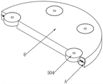
FIG. 2 is a perspective sectional view of the construction of a die plate according to the present invention;
FIG. 3 is a perspective view of a second partial structure of the present invention;
FIG. 4 is an enlarged view taken at A in FIG. 3;
fig. 5 is a perspective view of the positioning mechanism of the present invention.
In the figure: 1. a body; 2. a bending mechanism; 3. a shearing mechanism; 4. a work table; 5. a punching mechanism; 6. a pressing mechanism; 7. a positioning mechanism; 8. a mold plate; 501. a first drive lever; 502. a second drive lever; (ii) a 504. Supporting a die by punching; 505. punching a disc; 506. punching a male die; 507. a compression member; 508. a hydraulic cylinder; 601. a chute; 602. a limiting groove; 603. an insertion block; 604. a resistant column; 605. a limiting block; 606. a return spring; 701. a support plate; 702. a guide bar; 703. a screw rod; 704. a servo motor; 705. a slider; 706. a connecting plate; 707. a right-angle push plate; 708. a first positioning bolt; 709. positioning a plate; 710. and a second positioning bolt.
Detailed Description
The technical solutions in the embodiments of the present invention will be clearly and completely described below with reference to the drawings in the embodiments of the present invention, and it is obvious that the described embodiments are only a part of the embodiments of the present invention, and not all of the embodiments. All other embodiments, which can be derived by a person skilled in the art from the embodiments given herein without making any creative effort, shall fall within the protection scope of the present invention.
Referring to fig. 1-5, the present invention provides a technical solution: a numerical control automatic positioning three-station hydraulic bus processing machine for copper bar punching comprises a machine body 1, a bending mechanism 2 and a shearing mechanism 3, wherein the bending mechanism 2 and the shearing mechanism 3 are both fixedly installed at the top of the machine body 1, a workbench 4 is arranged on one side of the shearing mechanism 3, the workbench 4 is fixedly connected with one side of the machine body 1, a punching mechanism 5 is arranged on the workbench 4, a positioning mechanism 7 is arranged on one side of the punching mechanism 5, a die disc 8 is arranged on the punching mechanism 5, and a pressing mechanism 6 is arranged on the die disc 8; the pressing mechanism 6 comprises a sliding groove 601 formed in a die disc 8, a limiting groove 602 is formed in the sliding groove 601, an inserting block 603 is connected in the sliding groove 601 in a sliding manner, one end of the inserting block 603 is fixedly connected with a resisting column 604, the other end of the resisting column 604 is located in the sliding groove 601 and penetrates through the die disc 8, a limiting block 605 is fixedly connected on the resisting column 604, the limiting block 605 is located in the limiting groove 602, a reset spring 606 is sleeved on the outer wall of the resisting column 604, the reset spring 606 is located in the limiting groove 602, the reset spring 606 is located on the inner side of the limiting block 605, the resisting column 604 is pressed inwards, the inserting block 603 is driven to move towards one side of a groove at the bottom end of the punching supporting die 504, the inserting block 603 enables the punching supporting die 504 to be lifted upwards, then the punching supporting die 504 is replaced, the resisting column 604 is released, and the position of the inserting block 603 is restored under the elastic acting force of the reset spring 606; the punching mechanism 5 comprises a first driving rod 501 and a second driving rod 502 which are arranged on the workbench 4, a punching disc 505 is fixedly connected to the second driving rod 502, a punching male die 506 is arranged on the punching disc 505, a pressing piece 507 is fixedly connected to the tops of the first driving rod 501 and the second driving rod 502, and a hydraulic cylinder 508 is arranged between the workbenches 4; six groups of punching male dies 506 are arranged, and the pressing piece 507 is positioned right above one group of punching male dies 506; six groups of punching supporting dies 504 corresponding to the punching male dies 506 in position are arranged on the die disc 8, a groove matched with the inserting block 603 is formed in one side of the bottom end of each punching supporting die 504, the die disc 8 is rotatably connected with the second driving rod 502, and the die disc 8 is positioned at the upper end of the workbench 4 and is rotatably connected with the workbench 4; the mould disc 8 is rotatably connected with the second driving rod 502, and the mould disc 8 is positioned at the upper end of the workbench 4 and is rotatably connected with the workbench 4; the positioning mechanism 7 comprises symmetrical support plates 701 fixedly mounted on the top of the workbench 4, symmetrical guide rods 702 are fixedly connected between the symmetrical support plates 701, screw rods 703 are rotatably connected between the symmetrical support plates 701 through bearings, a servo motor 704 is fixedly connected to the outer side ends of the support plates 701, the output end of the servo motor 704 is fixedly connected with one end of each screw rod 703, a sliding block 705 is sleeved on each guide rod 702 and each screw rod 703, and each sliding block 705 is in threaded connection with each screw rod 703; the positioning mechanism 7 further comprises a right-angle push plate 707 in sliding connection with the top of the workbench 4, one end of the right-angle push plate 707 is provided with a first positioning bolt 708, the inner side end of the right-angle push plate 707 is in sliding connection with a positioning plate 709, and the top of the positioning plate 709 is provided with a second positioning bolt 710; the top of right angle push pedal 707 and the bottom fixed connection of connecting plate 706, the top surface of right angle push pedal 707 is provided with the scale that is suitable for with locating plate 709, the top surface of workstation 4 is provided with the scale that is suitable for right angle push pedal 707, open servo motor 704, it rotates to drive lead screw 703, lead screw 703 drives threaded connection and removes connecting plate 706, connecting plate 706 drives right angle push pedal 707 and removes the location according to the scale on workstation 4, and fix right angle push pedal 707 through first positioning bolt 708, remove locating plate 709 to suitable position according to right angle push pedal 707 surface scale again, and fix through second positioning bolt 710, place the copper bar in locating plate 709 and right angle push pedal 707 department, can be automatic high-efficient, accurate fix a position the copper bar work piece, the efficiency and the precision that the copper bar work piece punched a hole have been improved greatly, and the product quality is improved.
And those not described in detail in this specification are well within the skill of those in the art.
During operation, the position of the positioning mechanism 7 is adjusted according to the specification of the copper bar, the servo motor 704 is started to drive the screw rod 703 to rotate, the screw rod 703 drives the threaded connection connecting plate 706 to move, the connecting plate 706 drives the right-angle push plate 707 to move and position according to the scale on the workbench 4, the right-angle push plate 707 is fixed through the first positioning bolt 708, the positioning plate 709 is moved to a proper position according to the scale on the surface of the right-angle push plate 707 and is fixed through the second positioning bolt 710, the copper bar is placed at the positioning plate 709 and the right-angle push plate 707, and the copper bar is placed on the punching support die 504 to cover the punching position; starting a hydraulic cylinder 508 to drive the first driving rod 501, the second driving rod 502 and the pressing piece 507 to descend, so that the pressing piece 507 presses the punching male die 506 downwards to punch the copper bar; when other punching support dies 504 are needed, the abutting column 604 is pressed inwards to drive the inserting block 603 to move towards one side of the groove at the bottom end of the punching support die 504, so that the inserting block 603 supports the punching support die 504 upwards, the punching support die 504 is replaced, the abutting column 604 is loosened, the position of the inserting block 603 is restored under the elastic action force of the reset spring 606, and the working principle of the numerical control automatic positioning three-station hydraulic bus processing machine for punching copper bars is realized.
It is noted that, herein, relational terms such as first and second, and the like may be used solely to distinguish one entity or action from another entity or action without necessarily requiring or implying any actual such relationship or order between such entities or actions. Also, the terms "comprises," "comprising," or any other variation thereof, are intended to cover a non-exclusive inclusion, such that a process, method, article, or apparatus that comprises a list of elements does not include only those elements but may include other elements not expressly listed or inherent to such process, method, article, or apparatus.
Although embodiments of the present invention have been shown and described, it will be appreciated by those skilled in the art that changes, modifications, substitutions and alterations can be made in these embodiments without departing from the principles and spirit of the invention, the scope of which is defined in the appended claims and their equivalents.
Claims (8)
1. The utility model provides a copper bar punches a hole with three station hydraulic pressure generating line processing machines of numerical control automatic positioning, includes organism (1), bends mechanism (2) and cuts mechanism (3), bend mechanism (2) and cut the top of the equal fixed mounting of mechanism (3) at organism (1), its characterized in that: a workbench (4) is arranged on one side of the shearing mechanism (3), the workbench (4) is fixedly connected with one side of the machine body (1), a punching mechanism (5) is arranged on the workbench (4), a positioning mechanism (7) is arranged on one side of the punching mechanism (5), a die disc (8) is arranged on the punching mechanism (5), and a pressing mechanism (6) is arranged on the die disc (8);
pressing means (6) include spout (601) offering at mould dish (8), spacing groove (602) have been seted up on spout (601), sliding connection has plug block (603) in spout (601), the one end fixedly connected with of plug block (603) is resisted post (604), the other end that resists post (604) is located spout (601) and runs through mould dish (8), resist fixedly connected with stopper (605) on post (604), and stopper (605) are located spacing groove (602), reset spring (606) have been cup jointed to the outer wall that resists post (604), reset spring (606) are located spacing groove (602) and reset spring (606) are located the inboard of stopper (605).
2. The numerical control automatic positioning three-station hydraulic bus processing machine for punching copper bars according to claim 1, which is characterized in that: mechanism (5) of punching a hole includes first actuating lever (501) and second actuating lever (502) that are provided with on workstation (4), fixedly connected with punching press dish (505) on second actuating lever (502), be provided with punch a hole terrace die (506) on punching press dish (505), the top fixedly connected with of first actuating lever (501) and second actuating lever (502) compresses tightly piece (507), be provided with pneumatic cylinder (508) between workstation (4).
3. The numerical control automatic positioning three-station hydraulic bus processing machine for punching copper bars according to claim 2, which is characterized in that: six groups of punching male dies (506) are arranged, and the pressing piece (507) is positioned right above one group of punching male dies (506).
4. The numerical control automatic positioning three-station hydraulic bus processing machine for punching copper bars according to claim 3, which is characterized in that: the punching die carrier (504) is arranged on the die disc (8) and corresponds to the punching male die (506) in position, a groove matched with the insertion block (603) is formed in one side of the bottom end of the punching die carrier (504), the die disc (8) is rotatably connected with the second driving rod (502), and the upper end of the die disc (8) located on the workbench (4) is rotatably connected with the workbench (4).
5. The numerical control automatic positioning three-station hydraulic bus processing machine for punching copper bars according to claim 4, which is characterized in that: the die disc (8) is rotatably connected with the second driving rod (502), and the die disc (8) is positioned at the upper end of the workbench (4) and is rotatably connected with the workbench (4).
6. The numerical control automatic positioning three-station hydraulic bus processing machine for punching copper bars according to claim 5, which is characterized in that: the positioning mechanism (7) comprises supporting plates (701) which are fixedly mounted at the top of the workbench (4) and are symmetrical, guide rods (702) which are symmetrical are fixedly connected between the supporting plates (701) and are symmetrical, a screw rod (703) is rotatably connected between the supporting plates (701) through a bearing, a servo motor (704) is fixedly connected to the outer side end of each supporting plate (701), the output end of the servo motor (704) is fixedly connected with one end of the screw rod (703), a sliding block (705) is sleeved on each guide rod (702) and the screw rod (703), and the sliding block (705) is in threaded connection with the screw rod (703).
7. The numerical control automatic positioning three-station hydraulic bus processing machine for punching copper bars according to claim 6, which is characterized in that: the positioning mechanism (7) further comprises a right-angle push plate (707) connected with the top of the workbench (4) in a sliding mode, a first positioning bolt (708) is arranged at one end of the right-angle push plate (707), a positioning plate (709) is connected to the inner side end of the right-angle push plate (707) in a sliding mode, and a second positioning bolt (710) is arranged at the top of the positioning plate (709).
8. The numerical control automatic positioning three-station hydraulic bus processing machine for punching copper bars according to claim 7, which is characterized in that: the top of right angle push pedal (707) and the bottom fixed connection of connecting plate (706), the top surface of right angle push pedal (707) is provided with the scale that is suitable for with locating plate (709), the top surface of workstation (4) is provided with the scale that is suitable for right angle push pedal (707).
Priority Applications (1)
| Application Number | Priority Date | Filing Date | Title |
|---|---|---|---|
| CN202210167183.0A CN114535405A (en) | 2022-02-23 | 2022-02-23 | Numerical control automatic positioning three-station hydraulic bus processing machine for copper bar punching |
Applications Claiming Priority (1)
| Application Number | Priority Date | Filing Date | Title |
|---|---|---|---|
| CN202210167183.0A CN114535405A (en) | 2022-02-23 | 2022-02-23 | Numerical control automatic positioning three-station hydraulic bus processing machine for copper bar punching |
Publications (1)
| Publication Number | Publication Date |
|---|---|
| CN114535405A true CN114535405A (en) | 2022-05-27 |
Family
ID=81678482
Family Applications (1)
| Application Number | Title | Priority Date | Filing Date |
|---|---|---|---|
| CN202210167183.0A Withdrawn CN114535405A (en) | 2022-02-23 | 2022-02-23 | Numerical control automatic positioning three-station hydraulic bus processing machine for copper bar punching |
Country Status (1)
| Country | Link |
|---|---|
| CN (1) | CN114535405A (en) |
Cited By (1)
| Publication number | Priority date | Publication date | Assignee | Title |
|---|---|---|---|---|
| CN117753865A (en) * | 2024-01-19 | 2024-03-26 | 广东联大电气设备有限公司 | Copper bar processing device |
-
2022
- 2022-02-23 CN CN202210167183.0A patent/CN114535405A/en not_active Withdrawn
Cited By (1)
| Publication number | Priority date | Publication date | Assignee | Title |
|---|---|---|---|---|
| CN117753865A (en) * | 2024-01-19 | 2024-03-26 | 广东联大电气设备有限公司 | Copper bar processing device |
Similar Documents
| Publication | Publication Date | Title |
|---|---|---|
| CN105436302A (en) | Numerically-controlled processing integrated machine for copper bar | |
| CN202155423U (en) | Battery metal shell manufacturing equipment | |
| CN210098710U (en) | Waste material shaping device is cut in aluminium die casting punching a hole | |
| CN211191593U (en) | Compound burring device of aluminium die casting | |
| CN113363787B (en) | Transformer tap switch and body lead rapid crimping equipment capable of being guided and constrained | |
| CN211027730U (en) | Positioner of copper bar piercing press | |
| CN219703206U (en) | Numerical control punch with multimode utensil switching function | |
| CN108747403B (en) | Bending device for inner hexagonal wrench | |
| CN219188304U (en) | Multistation formula nameplate processing cross cutting mechanism | |
| CN218224402U (en) | Punch forming device for petroleum machinery parts | |
| CN211888615U (en) | Punching device of three-station bus processing machine | |
| CN214976983U (en) | Stamping device for aluminum card slot | |
| CN209843369U (en) | Five-die-position hydraulic bus processing device | |
| CN101722227A (en) | Collecting pipe flat hole punching device | |
| CN212021646U (en) | Stamping die of ABS draw-bar box | |
| CN220092818U (en) | A copper row cutting mold | |
| CN117753865A (en) | Copper bar processing device | |
| CN220837441U (en) | Distributor processing punch press | |
| CN216655951U (en) | Stamping equipment of low defective percentage | |
| CN212602308U (en) | Fixed-number cutting mechanism for continuous stamping die | |
| CN220532750U (en) | Shoe-shaped gold ingot stamping die | |
| CN219766512U (en) | Aluminum alloy section bar punch press convenient to collect waste material | |
| CN219648475U (en) | Stamping die that hardware processing was used | |
| CN220837327U (en) | Bending device for sheet metal part production | |
| CN219805226U (en) | Stamping die for wooden house fittings |
Legal Events
| Date | Code | Title | Description |
|---|---|---|---|
| PB01 | Publication | ||
| PB01 | Publication | ||
| SE01 | Entry into force of request for substantive examination | ||
| SE01 | Entry into force of request for substantive examination | ||
| WW01 | Invention patent application withdrawn after publication | ||
| WW01 | Invention patent application withdrawn after publication |
Application publication date: 20220527 |