CN114532194A - A irrigation equipment for forestry is grown seedlings - Google Patents
A irrigation equipment for forestry is grown seedlings Download PDFInfo
- Publication number
- CN114532194A CN114532194A CN202210184844.0A CN202210184844A CN114532194A CN 114532194 A CN114532194 A CN 114532194A CN 202210184844 A CN202210184844 A CN 202210184844A CN 114532194 A CN114532194 A CN 114532194A
- Authority
- CN
- China
- Prior art keywords
- box
- fixedly connected
- bevel gear
- stirring
- rod
- Prior art date
- Legal status (The legal status is an assumption and is not a legal conclusion. Google has not performed a legal analysis and makes no representation as to the accuracy of the status listed.)
- Withdrawn
Links
- 230000002262 irrigation Effects 0.000 title claims abstract description 30
- 238000003973 irrigation Methods 0.000 title claims abstract description 30
- 238000003756 stirring Methods 0.000 claims abstract description 55
- 239000007921 spray Substances 0.000 claims abstract description 11
- XLYOFNOQVPJJNP-UHFFFAOYSA-N water Substances O XLYOFNOQVPJJNP-UHFFFAOYSA-N 0.000 claims description 50
- 239000007788 liquid Substances 0.000 claims description 16
- 238000005086 pumping Methods 0.000 claims description 5
- 238000005507 spraying Methods 0.000 abstract description 6
- 238000003466 welding Methods 0.000 description 6
- 244000309464 bull Species 0.000 description 5
- 239000003814 drug Substances 0.000 description 3
- 230000007547 defect Effects 0.000 description 1
- 239000003651 drinking water Substances 0.000 description 1
- 235000020188 drinking water Nutrition 0.000 description 1
- 238000004134 energy conservation Methods 0.000 description 1
- 238000009434 installation Methods 0.000 description 1
- 239000000463 material Substances 0.000 description 1
- 238000010297 mechanical methods and process Methods 0.000 description 1
- 239000000203 mixture Substances 0.000 description 1
- 239000002689 soil Substances 0.000 description 1
- 239000013589 supplement Substances 0.000 description 1
Images



Classifications
-
- A—HUMAN NECESSITIES
- A01—AGRICULTURE; FORESTRY; ANIMAL HUSBANDRY; HUNTING; TRAPPING; FISHING
- A01G—HORTICULTURE; CULTIVATION OF VEGETABLES, FLOWERS, RICE, FRUIT, VINES, HOPS OR SEAWEED; FORESTRY; WATERING
- A01G25/00—Watering gardens, fields, sports grounds or the like
- A01G25/09—Watering arrangements making use of movable installations on wheels or the like
-
- A—HUMAN NECESSITIES
- A01—AGRICULTURE; FORESTRY; ANIMAL HUSBANDRY; HUNTING; TRAPPING; FISHING
- A01C—PLANTING; SOWING; FERTILISING
- A01C23/00—Distributing devices specially adapted for liquid manure or other fertilising liquid, including ammonia, e.g. transport tanks or sprinkling wagons
- A01C23/04—Distributing under pressure; Distributing mud; Adaptation of watering systems for fertilising-liquids
- A01C23/042—Adding fertiliser to watering systems
-
- A—HUMAN NECESSITIES
- A01—AGRICULTURE; FORESTRY; ANIMAL HUSBANDRY; HUNTING; TRAPPING; FISHING
- A01M—CATCHING, TRAPPING OR SCARING OF ANIMALS; APPARATUS FOR THE DESTRUCTION OF NOXIOUS ANIMALS OR NOXIOUS PLANTS
- A01M7/00—Special adaptations or arrangements of liquid-spraying apparatus for purposes covered by this subclass
- A01M7/0025—Mechanical sprayers
- A01M7/0032—Pressure sprayers
- A01M7/0042—Field sprayers, e.g. self-propelled, drawn or tractor-mounted
-
- A—HUMAN NECESSITIES
- A01—AGRICULTURE; FORESTRY; ANIMAL HUSBANDRY; HUNTING; TRAPPING; FISHING
- A01M—CATCHING, TRAPPING OR SCARING OF ANIMALS; APPARATUS FOR THE DESTRUCTION OF NOXIOUS ANIMALS OR NOXIOUS PLANTS
- A01M7/00—Special adaptations or arrangements of liquid-spraying apparatus for purposes covered by this subclass
- A01M7/005—Special arrangements or adaptations of the spraying or distributing parts, e.g. adaptations or mounting of the spray booms, mounting of the nozzles, protection shields
-
- B—PERFORMING OPERATIONS; TRANSPORTING
- B02—CRUSHING, PULVERISING, OR DISINTEGRATING; PREPARATORY TREATMENT OF GRAIN FOR MILLING
- B02C—CRUSHING, PULVERISING, OR DISINTEGRATING IN GENERAL; MILLING GRAIN
- B02C18/00—Disintegrating by knives or other cutting or tearing members which chop material into fragments
- B02C18/06—Disintegrating by knives or other cutting or tearing members which chop material into fragments with rotating knives
- B02C18/14—Disintegrating by knives or other cutting or tearing members which chop material into fragments with rotating knives within horizontal containers
-
- B—PERFORMING OPERATIONS; TRANSPORTING
- B05—SPRAYING OR ATOMISING IN GENERAL; APPLYING FLUENT MATERIALS TO SURFACES, IN GENERAL
- B05B—SPRAYING APPARATUS; ATOMISING APPARATUS; NOZZLES
- B05B15/00—Details of spraying plant or spraying apparatus not otherwise provided for; Accessories
- B05B15/20—Arrangements for agitating the material to be sprayed, e.g. for stirring, mixing or homogenising
- B05B15/25—Arrangements for agitating the material to be sprayed, e.g. for stirring, mixing or homogenising using moving elements, e.g. rotating blades
-
- B—PERFORMING OPERATIONS; TRANSPORTING
- B05—SPRAYING OR ATOMISING IN GENERAL; APPLYING FLUENT MATERIALS TO SURFACES, IN GENERAL
- B05B—SPRAYING APPARATUS; ATOMISING APPARATUS; NOZZLES
- B05B15/00—Details of spraying plant or spraying apparatus not otherwise provided for; Accessories
- B05B15/60—Arrangements for mounting, supporting or holding spraying apparatus
- B05B15/68—Arrangements for adjusting the position of spray heads
-
- Y—GENERAL TAGGING OF NEW TECHNOLOGICAL DEVELOPMENTS; GENERAL TAGGING OF CROSS-SECTIONAL TECHNOLOGIES SPANNING OVER SEVERAL SECTIONS OF THE IPC; TECHNICAL SUBJECTS COVERED BY FORMER USPC CROSS-REFERENCE ART COLLECTIONS [XRACs] AND DIGESTS
- Y02—TECHNOLOGIES OR APPLICATIONS FOR MITIGATION OR ADAPTATION AGAINST CLIMATE CHANGE
- Y02A—TECHNOLOGIES FOR ADAPTATION TO CLIMATE CHANGE
- Y02A40/00—Adaptation technologies in agriculture, forestry, livestock or agroalimentary production
- Y02A40/10—Adaptation technologies in agriculture, forestry, livestock or agroalimentary production in agriculture
- Y02A40/25—Greenhouse technology, e.g. cooling systems therefor
Landscapes
- Life Sciences & Earth Sciences (AREA)
- Engineering & Computer Science (AREA)
- Environmental Sciences (AREA)
- Water Supply & Treatment (AREA)
- Insects & Arthropods (AREA)
- Pest Control & Pesticides (AREA)
- Wood Science & Technology (AREA)
- Zoology (AREA)
- Food Science & Technology (AREA)
- Soil Sciences (AREA)
- Mechanical Engineering (AREA)
- Cultivation Receptacles Or Flower-Pots, Or Pots For Seedlings (AREA)
Abstract
The invention belongs to the technical field of irrigation for seedling growth, and particularly relates to irrigation equipment for seedling growth, aiming at the problems that the existing irrigation equipment for seedling growth needs to manually adjust the angle of a spray pipe when seedling growth is irrigated, which is troublesome and labor-consuming and reduces the working efficiency, the irrigation equipment for seedling growth comprises a bottom plate, wherein the top of the bottom plate is fixedly provided with a stirring box, the stirring box is rotationally connected with a stirring rod, the inner wall of the bottom of the stirring box is fixedly provided with a waterproof box, one end of the stirring rod is fixedly connected with a driving bevel gear, the driving bevel gear is positioned in the waterproof box, the left side of the waterproof box is rotationally connected with a first connecting rotating rod, and one end of the first connecting rotating rod is fixedly connected with a first bevel gear. The automatic reciprocating spraying pipe irrigation device is simple in structure, can automatically swing the spraying pipe in a reciprocating mode when seedlings are irrigated, saves labor, improves working efficiency and is convenient for people to use.
Description
Technical Field
The invention relates to the technical field of irrigation for seedling growth, in particular to irrigation equipment for seedling growth.
Background
The seedling raising means the raising of seedlings. The original meaning is that the seedlings are cultivated in a nursery, a hotbed or a greenhouse and are ready to be transplanted into the land for planting. It can also refer to the stage of various organisms after artificial protection until they can survive independently. In common words, "the seedling is strong and half harvested". The seedling culture is a work with high labor intensity, time consumption and strong technical performance. The irrigation of seedling growth utilizes manual or mechanical method with the form of irrigating of difference, supplements the soil moisture in gardens greenery patches, satisfies the moisture demand of sapling, and irrigation system will pay attention to the water demand requirement of cooperation plant, considers water conservation and energy-conservation, convenient and practical, can also promote the growth of sapling simultaneously.
Current irrigation equipment for forestry is grown seedlings, when irrigating growing seedlings, need the manual work to carry out angle modulation to the shower, take trouble hard, reduced work efficiency.
Disclosure of Invention
The invention aims to solve the defects that when the existing irrigation equipment for seedling growth is used for irrigating seedling growth, the angle of a spray pipe needs to be adjusted manually, the labor and the time are wasted, and the working efficiency is reduced.
In order to achieve the purpose, the invention adopts the following technical scheme:
an irrigation device for seedling growth in forestry, comprising a bottom plate, wherein a stirring box is fixedly arranged at the top of the bottom plate, a stirring rod is rotatably connected in the stirring box, a waterproof box is fixedly arranged on the inner wall of the bottom of the stirring box, one end of the stirring rod is fixedly connected with a driving bevel gear, the driving bevel gear is positioned in the waterproof box, the left side of the waterproof box is rotatably connected with a first connecting rotating rod, one end of the first connecting rotating rod is fixedly connected with a first bevel gear, the first bevel gear is meshed with the driving bevel gear, the stirring rod can drive the first bevel gear to rotate through the driving bevel gear, a supporting box is fixedly arranged on the bottom plate, a connecting box is fixedly arranged in the supporting box, one end of a first connecting rod is fixedly connected with a reduction gear, the reduction gear is positioned in the connecting box, a rotating shaft is rotatably connected in the connecting box, a large gear is fixedly connected on the rotating shaft, and is meshed with the large gear, the first connecting rotating rod can drive the large gear to rotate through the first reduction gear, one end of the rotating shaft is fixedly connected with the cylindrical disc, the connecting box is internally provided with a reciprocating mechanism, and the reciprocating mechanism is connected with the cylindrical disc.
Preferably, the bottom plate is fixedly provided with a water tank, the water tank is provided with a water pump, a water inlet of the water pump is communicated with the water tank through a same water pumping pipe, and a water outlet of the water pump is communicated with the stirring box through a same water delivery pipe.
Preferably, reciprocating mechanism includes hollow core plate, the slide bar, two connecting plates, the rack, the rotary rod, driven gear and shower, hollow core plate and cylinder dish swing joint, slide bar and hollow core plate fixed connection, and slide bar and connecting box sliding connection, two connecting plates and hollow core plate fixed connection, rack and two connecting plate fixed connection, remove about two connecting plates of hollow core plate accessible drive rack, the rotary rod with prop case swivelling joint, driven gear and rotary rod fixed connection, and driven gear meshes with the rack mutually, the one end fixed connection of shower and rotary rod, the rotary rod can drive the reciprocating swing of shower.
Preferably, the right side of the waterproof box is rotatably connected with a second connecting rotating rod, one end of the second connecting rotating rod is fixedly connected with a second bevel gear, the second bevel gear is meshed with the driving bevel gear, the right side of the stirring box is communicated with a connecting cylinder, one end of the second connecting rotating rod is fixedly connected with a blade, and a filter screen is arranged in the connecting cylinder.
Preferably, the one end intercommunication of connecting cylinder has the connector, and the one end intercommunication of connector has the drawing liquid pump, and the intercommunication has the transfer line between drawing liquid pump and the shower, is equipped with the feed inlet on the agitator tank, fixedly connected with stirring leaf on the puddler, and the top fixed mounting of agitator tank has the motor case, and fixed mounting has driving motor in the motor case, driving motor's output shaft and puddler fixed connection.
Compared with the prior art, the invention has the advantages that:
(1) this scheme is owing to set up hollow core plate and driven the slide bar and slide on the connecting box, and hollow core plate moves about through two connecting plates drive rack, and the rack drives driven gear reciprocating rotation, and driven gear drives the rotary rod and rotates, and the rotary rod drives the reciprocal swing of shower, has realized reciprocal wobbling purpose.
(2) This scheme is connected the bull stick and is rotated through the second bevel gear drive second owing to set up the drive bevel gear, and the bull stick is connected to the second drives the blade rotation, can smash debris, prevents that the filter screen from blockking up, has realized the kibbling purpose of debris.
The automatic reciprocating spraying pipe irrigation device is simple in structure, can automatically swing the spraying pipe in a reciprocating mode when seedlings are irrigated, saves labor, improves working efficiency and is convenient for people to use.
Drawings
Fig. 1 is a schematic structural view of an irrigation device for forest seedling raising according to the present invention;
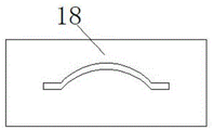
fig. 2 is a schematic side view of a hollow board of an irrigation device for forest seedling raising according to the present invention;
fig. 3 is a schematic structural view of part a of irrigation equipment for forest seedling raising according to the invention;
fig. 4 is a schematic top view of a spreader box of an irrigation apparatus for forest seedling raising according to the present invention;
fig. 5 is a schematic perspective view of a connector of irrigation equipment for seedling growth according to the present invention.
In the figure: 1. a base plate; 2. a stirring box; 3. a stirring rod; 4. a waterproof box; 5. a drive bevel gear; 6. a first connecting rotating rod; 7. a first bevel gear; 8. supporting the box; 9. a connecting box; 10. a reduction gear; 11. a rotating shaft; 12. a bull gear; 13. a cylindrical disk; 14. a water tank; 15. a water pumping pipe; 16. a water pump; 17. a water delivery pipe; 18. a hollow slab; 19. a slide bar; 20. a connecting plate; 21. a rack; 22. rotating the rod; 23. a driven gear; 24. a shower pipe; 25. a second connecting rotating rod; 26. a second bevel gear; 27. a connecting cylinder; 28. a blade; 29. a filter screen; 30. a connector; 31. a liquid pump; 32. a transfusion tube; 33. stirring blades; 34. a motor case; 35. a drive motor; 36. a telescopic rod; 37. a movable seat; 38. an electric push rod.
Detailed Description
The technical solution in this embodiment will be clearly and completely described below with reference to the drawings in this embodiment.
Example one
Referring to fig. 1-5, an irrigation device for seedling growth in forestry, comprising a bottom plate 1, a stirring tank 2 fixedly installed at the top of the bottom plate 1, a stirring rod 3 rotatably connected to the stirring tank 2, a waterproof tank 4 fixedly installed on the inner wall of the bottom of the stirring tank 2, a driving bevel gear 5 fixedly connected to one end of the stirring rod 3, the driving bevel gear 5 located in the waterproof tank 4, a first connecting rotating rod 6 rotatably connected to the left side of the waterproof tank 4, a first bevel gear 7 fixedly connected to one end of the first connecting rotating rod 6, the first bevel gear 7 engaged with the driving bevel gear 5, the stirring rod 3 driving the first bevel gear 7 to rotate via the driving bevel gear 5, a supporting box 8 fixedly installed on the bottom plate 1, a connecting box 9 fixedly installed in the supporting box 8, a reduction gear 10 fixedly connected to one end of the first connecting rod 6, the reduction gear 10 located in the connecting box 9, a rotating shaft 11 rotatably connected to the connecting box 9, a large gear 12 is fixedly connected to the rotating shaft 11, the large gear 12 is meshed with the reduction gear 10, the first connecting rotating rod 6 can drive the large gear 12 to rotate through the first reduction gear 10, a cylindrical disc 13 is fixedly connected to one end of the rotating shaft 11, a reciprocating mechanism is arranged in the connecting box 9, and the reciprocating mechanism is connected with the cylindrical disc 13.
In this embodiment, a water tank 14 is fixedly mounted on the bottom plate 1, a water pump 16 is arranged on the water tank 14, a water inlet of the water pump 16 is communicated with the water tank 14 through a same water pumping pipe 15, and a water outlet of the water pump 16 is communicated with the stirring box 2 through a same water conveying pipe 17.
In this embodiment, the reciprocating mechanism includes a hollow plate 18, a sliding rod 19, two connecting plates 20, a rack 21, a rotating rod 22, a driven gear 23 and a spray pipe 24, the hollow plate 18 is movably connected with the cylindrical disc 13, the sliding rod 19 is fixedly connected with the hollow plate 18, the sliding rod 19 is slidably connected with the connecting box 9, the two connecting plates 20 are fixedly connected with the hollow plate 18, the rack 21 is fixedly connected with the two connecting plates 20, the hollow plate 18 can drive the rack 21 to move left and right through the two connecting plates 20, the rotating rod 22 is rotatably connected with the supporting box 8, the driven gear 23 is fixedly connected with the rotating rod 22, the driven gear 23 is meshed with the rack 21, the spray pipe 24 is fixedly connected with one end of the rotating rod 22, and the rotating rod 22 can drive the spray pipe 24 to swing back and forth.
In this embodiment, the right side of the waterproof box 4 is rotatably connected with a second connecting rotating rod 25, one end of the second connecting rotating rod 25 is fixedly connected with a second bevel gear 26, the second bevel gear 26 is meshed with the driving bevel gear 5, the right side of the stirring box 2 is communicated with a connecting cylinder 27, one end of the second connecting rotating rod 25 is fixedly connected with a blade 28, and a filter screen 29 is arranged in the connecting cylinder 27.
In this embodiment, one end of the connecting cylinder 27 is communicated with a connecting head 30, one end of the connecting head 30 is communicated with a liquid pump 31, a liquid conveying pipe 32 is communicated between the liquid pump 31 and the spraying pipe 24, a feeding hole is formed in the stirring box 2, a stirring blade 33 is fixedly connected to the stirring rod 3, a motor box 34 is fixedly mounted at the top of the stirring box 2, a driving motor 35 is fixedly mounted in the motor box 34, and an output shaft of the driving motor 35 is fixedly connected with the stirring rod 3.
The working principle is as follows: when the device is used, a water pump 16 pumps water in a water tank 14 through a water pumping pipe 15 and conveys the water into a stirring box 2 through a water conveying pipe 17, liquid medicine is added into the stirring box 2 through a feed inlet, a driving motor 35 is started, an output shaft of the driving motor 35 drives a stirring rod 3 to rotate, the stirring rod 3 drives a stirring blade 33 to rotate and stir and mix the liquid medicine and the water, meanwhile, the stirring rod 3 drives a first bevel gear 7 to rotate through a driving bevel gear 5, the first bevel gear 7 drives a first connecting rotating rod 6 to rotate, the first connecting rotating rod 6 drives a reduction gear 10 to rotate, the first reduction gear 10 drives a large gear 12 to rotate, the large gear 12 drives a rotating shaft 11 to rotate, the rotating shaft 11 drives a cylindrical disc 13 to rotate, the cylindrical disc 13 drives a hollow plate 18 to move left and right, the hollow plate 18 drives a sliding rod 19 to slide on a connecting box 9, the hollow plate 18 drives a rack 21 to move left and right through two connecting plates 20, rack 21 drives driven gear 23 reciprocating rotation, driven gear 23 drives rotary rod 22 and rotates, rotary rod 22 drives shower 24 reciprocating swing, the liquid medicine in agitator tank 2 is taken out through connector 30 to drawing liquid pump 31 simultaneously, and carry to shower 24 through transfer line 32 and spray growing seedlings, the initiative taper gear drives the second through second bevel gear 26 and connects the bull stick 25 and rotate simultaneously, the bull stick 25 is connected to the second and drives the rotation of blade 28, can smash debris, prevent that filter screen 29 from blockking up.
Example two
Referring to fig. 1-5, an irrigation device for seedling growth in forestry, comprising a bottom plate 1, a stirring tank 2 welded and installed on the top of the bottom plate 1, a stirring rod 3 rotatably connected in the stirring tank 2, a waterproof tank 4 welded and installed on the inner wall of the bottom of the stirring tank 2, a driving bevel gear 5 welded and connected to one end of the stirring rod 3, the driving bevel gear 5 located in the waterproof tank 4, a first connecting rotating rod 6 rotatably connected to the left side of the waterproof tank 4, a first bevel gear 7 welded and connected to one end of the first connecting rotating rod 6, the first bevel gear 7 engaged with the driving bevel gear 5, the stirring rod 3 driving the first bevel gear 7 to rotate through the driving bevel gear 5, a supporting box 8 welded and installed on the bottom plate 1, a connecting box 9 welded and installed in the supporting box 8, a reduction gear 10 welded and connected to one end of the first connecting rod 6, the reduction gear 10 located in the connecting box 9, a rotating shaft 11 rotatably connected in the connecting box 9, a large gear 12 is welded on the rotating shaft 11, the large gear 12 is meshed with a reduction gear 10, the first connecting rotating rod 6 can drive the large gear 12 to rotate through the first reduction gear 10, a cylindrical disc 13 is welded at one end of the rotating shaft 11, a reciprocating mechanism is arranged in the connecting box 9, and the reciprocating mechanism is connected with the cylindrical disc 13.
In this embodiment, welding installation has water tank 14 on the bottom plate 1, is equipped with water pump 16 on the water tank 14, and the intercommunication has same drinking-water pipe 15 between water pump 16's water inlet and the water tank 14, and the intercommunication has same raceway 17 between water pump 16's delivery port and agitator tank 2.
In this embodiment, the reciprocating mechanism includes a hollow plate 18, a sliding rod 19, two connecting plates 20, a rack 21, a rotating rod 22, a driven gear 23 and a spray pipe 24, the hollow plate 18 is movably connected with the cylindrical disc 13, the sliding rod 19 is connected with the hollow plate 18 in a welding manner, the sliding rod 19 is connected with the connecting box 9 in a sliding manner, the two connecting plates 20 are connected with the hollow plate 18 in a welding manner, the rack 21 is connected with the two connecting plates 20 in a welding manner, the hollow plate 18 can drive the rack 21 to move left and right through the two connecting plates 20, the rotating rod 22 is connected with the supporting box 8 in a rotating manner, the driven gear 23 is connected with the rotating rod 22 in a welding manner, the driven gear 23 is meshed with the rack 21, the spray pipe 24 is connected with one end of the rotating rod 22 in a welding manner, and the rotating rod 22 can drive the spray pipe 24 to swing back and forth.
In this embodiment, the right side of the waterproof box 4 is rotatably connected with a second connecting rotating rod 25, one end of the second connecting rotating rod 25 is welded with a second bevel gear 26, the second bevel gear 26 is meshed with the driving bevel gear 5, the right side of the stirring box 2 is communicated with a connecting cylinder 27, one end of the second connecting rotating rod 25 is welded with a blade 28, and a filter screen 29 is arranged in the connecting cylinder 27.
In this embodiment, one end of the connecting cylinder 27 is communicated with a connecting head 30, one end of the connecting head 30 is communicated with a liquid pump 31, a liquid conveying pipe 32 is communicated between the liquid pump 31 and the spraying pipe 24, a feeding hole is formed in the stirring box 2, a stirring blade 33 is welded on the stirring rod 3, a motor box 34 is welded on the top of the stirring box 2, a driving motor 35 is welded in the motor box 34, and an output shaft of the driving motor 35 is welded with the stirring rod 3.
In this embodiment, the bottom of bottom plate 1 is welded and is connected with two telescopic links 36, and the one end welded connection of two telescopic links 36 has same removal seat 37, is equipped with electric putter 38 in the removal seat 37, and electric putter 38's one end and bottom plate 1 welded connection.
In this embodiment, the difference between the second embodiment and the first embodiment is: electric putter 38 drives bottom plate 1 rebound, and bottom plate 1 drives two telescopic link 36 extensions, and all structures in this application all can carry out the selection of material and length according to the in-service use condition, and the drawing is the schematic structure picture, and suitable adjustment can be made to specific actual dimensions.
Claims (8)
1. An irrigation device for seedling growth, which comprises a bottom plate (1) and is characterized in that a stirring box (2) is fixedly installed at the top of the bottom plate (1), a stirring rod (3) is rotationally connected in the stirring box (2), a waterproof box (4) is fixedly installed on the inner wall of the bottom of the stirring box (2), one end of the stirring rod (3) is fixedly connected with a driving bevel gear (5), the driving bevel gear (5) is positioned in the waterproof box (4), the left side of the waterproof box (4) is rotationally connected with a first connecting rotating rod (6), one end of the first connecting rotating rod (6) is fixedly connected with a first bevel gear (7), the first bevel gear (7) is meshed with the driving bevel gear (5), a supporting box (8) is fixedly installed on the bottom plate (1), a connecting box (9) is fixedly installed in the supporting box (8), one end of the first connecting rod (6) is fixedly connected with a reduction gear (10), reduction gear (10) are located connecting box (9), and the internal rotation of connecting box (9) is connected with axis of rotation (11), fixedly connected with gear wheel (12) on axis of rotation (11), and gear wheel (12) mesh with reduction gear (10) mutually, and one end fixedly connected with cylinder dish (13) of axis of rotation (11) is equipped with reciprocating mechanism in connecting box (9), and reciprocating mechanism is connected with cylinder dish (13).
2. An irrigation apparatus for forest seedling as claimed in claim 1, wherein the bottom plate (1) is fixedly provided with a water tank (14), the water tank (14) is provided with a water pump (16), a same water pumping pipe (15) is communicated between a water inlet of the water pump (16) and the water tank (14), and a same water delivery pipe (17) is communicated between a water outlet of the water pump (16) and the stirring tank (2).
3. An irrigation apparatus for forest seedling as claimed in claim 1, wherein the reciprocating mechanism comprises a hollow plate (18), a slide bar (19), two connecting plates (20), a rack (21), a rotating bar (22), a driven gear (23) and a spray pipe (24), the hollow plate (18) is movably connected with the cylindrical disc (13), the slide bar (19) is fixedly connected with the hollow plate (18), the slide bar (19) is slidably connected with the connecting box (9), the two connecting plates (20) are fixedly connected with the hollow plate (18), and the rack (21) is fixedly connected with the two connecting plates (20).
4. An irrigation apparatus for forest seedling cultivation as claimed in claim 3, characterized in that the rotary rod (22) is rotatably connected with the spreader box (8), the driven gear (23) is fixedly connected with the rotary rod (22), the driven gear (23) is meshed with the rack (21), and the shower pipe (24) is fixedly connected with one end of the rotary rod (22).
5. An irrigation apparatus for forest seedling as claimed in claim 1, characterized in that a second connecting rotating rod (25) is rotatably connected to the right side of the waterproof box (4), a second bevel gear (26) is fixedly connected to one end of the second connecting rotating rod (25), and the second bevel gear (26) is meshed with the driving bevel gear (5).
6. An irrigation apparatus for forest seedling as claimed in claim 5, characterized in that the right side of the agitator tank (2) is connected with a connecting cylinder (27), one end of the second connecting rotating rod (25) is fixedly connected with a blade (28), and a filter screen (29) is arranged in the connecting cylinder (27).
7. An irrigation apparatus for forest seedling as claimed in claim 6, wherein one end of the connecting cylinder (27) is communicated with a connector (30), one end of the connector (30) is communicated with a liquid pump (31), and a liquid conveying pipe (32) is communicated between the liquid pump (31) and the spray pipe (24).
8. An irrigation device for seedling growth according to claim 1, wherein the agitator tank (2) is provided with a feed inlet, the agitator arm (3) is fixedly connected with an agitator blade (33), the top of the agitator tank (2) is fixedly provided with a motor box (34), a driving motor (35) is fixedly arranged in the motor box (34), and an output shaft of the driving motor (35) is fixedly connected with the agitator arm (3).
Priority Applications (1)
| Application Number | Priority Date | Filing Date | Title |
|---|---|---|---|
| CN202210184844.0A CN114532194A (en) | 2022-02-28 | 2022-02-28 | A irrigation equipment for forestry is grown seedlings |
Applications Claiming Priority (1)
| Application Number | Priority Date | Filing Date | Title |
|---|---|---|---|
| CN202210184844.0A CN114532194A (en) | 2022-02-28 | 2022-02-28 | A irrigation equipment for forestry is grown seedlings |
Publications (1)
| Publication Number | Publication Date |
|---|---|
| CN114532194A true CN114532194A (en) | 2022-05-27 |
Family
ID=81679954
Family Applications (1)
| Application Number | Title | Priority Date | Filing Date |
|---|---|---|---|
| CN202210184844.0A Withdrawn CN114532194A (en) | 2022-02-28 | 2022-02-28 | A irrigation equipment for forestry is grown seedlings |
Country Status (1)
| Country | Link |
|---|---|
| CN (1) | CN114532194A (en) |
Cited By (1)
| Publication number | Priority date | Publication date | Assignee | Title |
|---|---|---|---|---|
| CN117837474A (en) * | 2024-01-19 | 2024-04-09 | 丽水小康农林技术服务有限公司 | A watering machine for raising seedlings in forestry engineering |
-
2022
- 2022-02-28 CN CN202210184844.0A patent/CN114532194A/en not_active Withdrawn
Cited By (1)
| Publication number | Priority date | Publication date | Assignee | Title |
|---|---|---|---|---|
| CN117837474A (en) * | 2024-01-19 | 2024-04-09 | 丽水小康农林技术服务有限公司 | A watering machine for raising seedlings in forestry engineering |
Similar Documents
| Publication | Publication Date | Title |
|---|---|---|
| CN210580283U (en) | Inside irrigation equipment who uses vegetables of farming big-arch shelter | |
| CN221059118U (en) | A conveniently adjustable spraying device for agricultural irrigation | |
| CN219812799U (en) | Soilless culture vegetable planting equipment | |
| CN214593132U (en) | A kind of sweet corn seedling cultivation support | |
| CN214015030U (en) | Forestry is with watering device that has filtering capability | |
| CN222170625U (en) | An agricultural greenhouse with convenient water supply | |
| CN212813340U (en) | Irrigation equipment of usefulness is cultivated to forestry | |
| CN222675159U (en) | Farm irrigation equipment | |
| CN224165194U (en) | Atomizer is used in golden camellia seedling culture | |
| CN218007496U (en) | An irrigation device for agricultural machinery | |
| CN222564640U (en) | Automatic irrigator for tea terraced fields | |
| CN222655929U (en) | Improved irrigation water delivery device | |
| CN220630478U (en) | Irrigation equipment | |
| CN218772931U (en) | Fertilizer injection unit for cowpea planting | |
| CN222340200U (en) | Spray type irrigation device | |
| CN214545617U (en) | A sprinkler for garden road flowers and plants | |
| CN223310392U (en) | Seedling transplanting device | |
| CN223979203U (en) | A jasmine plant seedling cultivation device | |
| CN216219314U (en) | Irrigation equipment of usefulness is cultivated to forestry | |
| CN222108567U (en) | Irrigation device for fruit tree nursery | |
| CN220545553U (en) | Automatic irrigation equipment of greenhouse vegetables | |
| CN220292567U (en) | Fertilizer injection unit is used in astragalus planting | |
| CN214126005U (en) | A crop regularly waters auxiliary assembly for vegetable planting | |
| CN219812782U (en) | An agricultural irrigation machine based on agricultural production | |
| CN218244954U (en) | Flower planting is with device that waters |
Legal Events
| Date | Code | Title | Description |
|---|---|---|---|
| PB01 | Publication | ||
| PB01 | Publication | ||
| SE01 | Entry into force of request for substantive examination | ||
| SE01 | Entry into force of request for substantive examination | ||
| WW01 | Invention patent application withdrawn after publication | ||
| WW01 | Invention patent application withdrawn after publication |
Application publication date: 20220527 |