CN114512914A - Incoming line cabinet capable of automatically adjusting temperature in cabinet - Google Patents

Incoming line cabinet capable of automatically adjusting temperature in cabinet Download PDF

Info

Publication number
CN114512914A
CN114512914A CN202210206369.2A CN202210206369A CN114512914A CN 114512914 A CN114512914 A CN 114512914A CN 202210206369 A CN202210206369 A CN 202210206369A CN 114512914 A CN114512914 A CN 114512914A
Authority
CN
China
Prior art keywords
dust
cabinet
side wall
air
incoming line
Prior art date
Legal status (The legal status is an assumption and is not a legal conclusion. Google has not performed a legal analysis and makes no representation as to the accuracy of the status listed.)
Granted
Application number
CN202210206369.2A
Other languages
Chinese (zh)
Other versions
CN114512914B (en
Inventor
陆奇
朱彬
Current Assignee (The listed assignees may be inaccurate. Google has not performed a legal analysis and makes no representation or warranty as to the accuracy of the list.)
Zhejiang Weijie Electric Co ltd
Original Assignee
Zhejiang Weijie Electric Co ltd
Priority date (The priority date is an assumption and is not a legal conclusion. Google has not performed a legal analysis and makes no representation as to the accuracy of the date listed.)
Filing date
Publication date
Application filed by Zhejiang Weijie Electric Co ltd filed Critical Zhejiang Weijie Electric Co ltd
Priority to CN202210206369.2A priority Critical patent/CN114512914B/en
Publication of CN114512914A publication Critical patent/CN114512914A/en
Application granted granted Critical
Publication of CN114512914B publication Critical patent/CN114512914B/en
Active legal-status Critical Current
Anticipated expiration legal-status Critical

Links

Images

Classifications

    • H—ELECTRICITY
    • H02—GENERATION; CONVERSION OR DISTRIBUTION OF ELECTRIC POWER
    • H02B—BOARDS, SUBSTATIONS OR SWITCHING ARRANGEMENTS FOR THE SUPPLY OR DISTRIBUTION OF ELECTRIC POWER
    • H02B1/00—Frameworks, boards, panels, desks, casings; Details of substations or switching arrangements
    • H02B1/26—Casings; Parts thereof or accessories therefor
    • H02B1/30—Cabinet-type casings; Parts thereof or accessories therefor
    • B—PERFORMING OPERATIONS; TRANSPORTING
    • B01—PHYSICAL OR CHEMICAL PROCESSES OR APPARATUS IN GENERAL
    • B01D—SEPARATION
    • B01D46/00—Filters or filtering processes specially modified for separating dispersed particles from gases or vapours
    • B01D46/30—Particle separators, e.g. dust precipitators, using loose filtering material
    • H—ELECTRICITY
    • H02—GENERATION; CONVERSION OR DISTRIBUTION OF ELECTRIC POWER
    • H02B—BOARDS, SUBSTATIONS OR SWITCHING ARRANGEMENTS FOR THE SUPPLY OR DISTRIBUTION OF ELECTRIC POWER
    • H02B1/00—Frameworks, boards, panels, desks, casings; Details of substations or switching arrangements
    • H02B1/26—Casings; Parts thereof or accessories therefor
    • H02B1/28—Casings; Parts thereof or accessories therefor dustproof, splashproof, drip-proof, waterproof or flameproof
    • H—ELECTRICITY
    • H02—GENERATION; CONVERSION OR DISTRIBUTION OF ELECTRIC POWER
    • H02B—BOARDS, SUBSTATIONS OR SWITCHING ARRANGEMENTS FOR THE SUPPLY OR DISTRIBUTION OF ELECTRIC POWER
    • H02B1/00—Frameworks, boards, panels, desks, casings; Details of substations or switching arrangements
    • H02B1/26—Casings; Parts thereof or accessories therefor
    • H02B1/30—Cabinet-type casings; Parts thereof or accessories therefor
    • H02B1/305—Cable entries
    • H—ELECTRICITY
    • H02—GENERATION; CONVERSION OR DISTRIBUTION OF ELECTRIC POWER
    • H02B—BOARDS, SUBSTATIONS OR SWITCHING ARRANGEMENTS FOR THE SUPPLY OR DISTRIBUTION OF ELECTRIC POWER
    • H02B1/00—Frameworks, boards, panels, desks, casings; Details of substations or switching arrangements
    • H02B1/56—Cooling; Ventilation
    • H02B1/565—Cooling; Ventilation for cabinets

Landscapes

  • Engineering & Computer Science (AREA)
  • Power Engineering (AREA)
  • Chemical & Material Sciences (AREA)
  • Chemical Kinetics & Catalysis (AREA)
  • Filtering Of Dispersed Particles In Gases (AREA)

Abstract

本发明涉及开关柜技术领域,且公开了一种箱内温度自动调节的进线柜,包括进线柜体和温度传感器,温度传感器固定连接于进线柜体的内部,进线柜体的内部设置有风冷机构,进线柜体的内部还设置有集尘机构,集尘机构包括除尘腔,除尘腔的内部铰接有集尘凹板,集尘凹板的外侧壁上开设有若干个出风孔,集尘凹板的内部固定连接有滤尘棉,集尘凹板的内部于滤尘棉的外侧壁设置有刮尘条。该箱内温度自动调节的进线柜,具备集中快速清理灰尘、保证电路运行通畅等优点,解决了现有的进线柜未对有效防尘进行妥善考虑,导致风机在为柜内输送气流时携带的灰尘不能及时集中清理,从而导致后续电路运行出现问题的问题。

Figure 202210206369

The invention relates to the technical field of switch cabinets, and discloses an incoming line cabinet with automatic temperature adjustment in the box, comprising an incoming line cabinet body and a temperature sensor, wherein the temperature sensor is fixedly connected to the inside of the incoming line cabinet body, and the inside of the incoming line cabinet body is An air-cooling mechanism is provided, and a dust-collecting mechanism is also provided inside the incoming line cabinet. The dust-collecting mechanism includes a dust-removing cavity. The interior of the dust-removing cavity is hinged with a dust-collecting concave plate. The inside of the air hole and the dust collecting concave plate is fixedly connected with a dust filter cotton, and the inside of the dust collecting concave plate is provided with a dust scraping strip on the outer side wall of the dust filter cotton. The inlet cabinet with automatic temperature adjustment in the box has the advantages of centralized and fast cleaning of dust, ensuring smooth operation of the circuit, etc., which solves the problem that the existing inlet cabinet does not properly consider effective dust prevention, which causes the fan to deliver airflow to the cabinet. The dust carried by it cannot be cleaned up in a centralized manner in time, which leads to the problem of subsequent circuit operation problems.

Figure 202210206369

Description

Incoming line cabinet capable of automatically adjusting temperature in cabinet
Technical Field
The invention relates to the technical field of switch cabinets, in particular to a wire inlet cabinet capable of automatically adjusting the temperature in a cabinet.
Background
The switch cabinet is an electrical device, the exterior line of the switch cabinet firstly enters a main control switch in the cabinet and then enters a branch control switch, and each branch is arranged according to the requirement. Such as instruments, automatic control, magnetic switches of motors, various alternating current contactors, and the like, some switch cabinets with high-voltage chambers and low-voltage chambers, high-voltage buses, such as power plants, and the like, and some switch cabinets with low-frequency load shedding for protecting main equipment, which can be divided into inlet cabinets, outlet cabinets, metering cabinets, compensation cabinets (capacitor cabinets), corner cabinets and bus cabinets according to purposes.
Because there is a large amount of loaded circuit switching device in the inlet wire cabinet, can produce a large amount of heats at the during operation, in order to stabilize the normal work of circuit, when the heat is too high in the cabinet, it is cooling to respond to the temperature to start the fan through temperature automatic regulating apparatus now more, so that the operation of the internal each circuit of assurance cabinet is stable, however, current inlet wire cabinet does not properly consider effective dustproof, the dust that leads to the fan to carry when carrying the air current in for the cabinet can not in time concentrate the clearance, thereby lead to follow-up circuit operation to go wrong, consequently, need an in-box temperature automatic regulating's inlet wire cabinet urgently.
Disclosure of Invention
Technical problem to be solved
Aiming at the defects of the prior art, the invention provides the incoming cabinet with the temperature automatically adjusted in the cabinet, which has the advantages of intensively and quickly cleaning dust, ensuring smooth circuit operation and the like, and solves the problem that the dust carried by a fan when the fan conveys airflow in the cabinet cannot be intensively cleaned in time due to the fact that effective dust prevention is not properly considered in the conventional incoming cabinet, so that the subsequent circuit operation is caused to be problematic.
(II) technical scheme
In order to achieve the purpose, the invention provides the following technical scheme: the incoming line cabinet capable of automatically adjusting the temperature in the box comprises an incoming line cabinet body and a temperature sensor, wherein the temperature sensor is fixedly connected inside the incoming line cabinet body;
the air cooling mechanism comprises an air pipe, an air net frame is arranged on one side of the air pipe, a quick-release assembly is arranged between the air pipe and the air net frame, the air pipe is movably connected with the air net frame through the quick-release assembly, a fan frame is fixedly connected inside the air net frame, and a fan is fixedly connected inside the fan frame;
the dust collection mechanism comprises a dust removal cavity, a dust collection concave plate is hinged inside the dust removal cavity, a plurality of air outlets are formed in the outer side wall of the dust collection concave plate, dust filter cotton is fixedly connected inside the dust collection concave plate, and a dust scraping strip is arranged on the outer side wall of the dust filter cotton inside the dust collection concave plate.
Preferably, the air pipe is fixedly connected to the outer side wall of the inlet wire cabinet body, and the air pipe is communicated with the inlet wire cabinet body.
The air duct is used for inducing air to enter the wire inlet cabinet body.
Preferably, the outer side wall of the wind screen frame is matched with the inner side wall of the opening of the air pipe, and the wind screen frame is located inside the inlet wire cabinet body.
Preferably, the quick detach subassembly includes spliced eye and inserted bar, spliced eye and inserted bar all are provided with four, four the spliced eye is seted up respectively and is close to both ends position department on two opposite faces of the inside wall of tuber pipe, four inserted bar swing joint is close to both ends position department respectively on two faces that deviate from mutually on the lateral wall of wind screen frame on the lateral wall of spliced bar difference, the spliced eye pegs graft with the inserted bar each other.
Because the fan needs uninterrupted operation, in order to guarantee its stability, need regularly overhaul it and maintain, consequently, in order to overhaul the maintenance conveniently, carry out swing joint through spliced eye and inserted bar between with tuber pipe and the air mesh frame, make things convenient for the dismouting, raise the efficiency.
Preferably, the bullet chamber has all been seted up to the position department that is close to four peg graft poles on the lateral wall of wind screen frame, four the one end of peg graft pole is pegged graft respectively in the inside in four bullet chambers, four the other end of peg graft pole extends in the outside in four bullet chambers.
Preferably, four the equal fixedly connected with of one end that is located the bullet intracavity on the grafting pole supports the piece, support piece and play chamber sliding connection, the cover is equipped with the spring on the lateral wall of grafting pole, the spring is located the inside in bullet chamber.
Preferably, the dust removal chamber is opened on the lateral wall of the inlet wire cabinet body and on the fan opposite face, the dust collection concave is protruded outside the lateral wall of the inlet wire cabinet body, and the dust collection concave is connected with the dust filtering cotton through a bolt.
The dust filter cotton can be disassembled and assembled on the dust collecting concave plate at any time through the bolts, so that the dust filter cotton is convenient to replace and clean.
Preferably, the two opposite faces of the inner side wall of the dust collection concave plate are provided with sliding grooves, the two opposite faces of the inner side wall of the dust collection concave plate are provided with sliding rods, the sliding rods are fixedly connected inside the sliding grooves, and the two ends of the dust scraping strips are connected with the two sliding rods in a sliding mode.
When needing to clear up the dirt cotton, open collection dirt concave plate, promote from top to bottom and scrape the dirt strip, scrape dirt strip surface and should contact with the cotton surface of dirt filter, can scrape the cotton surface of dirt filter when promoting from top to bottom and scraping the dirt strip, convenient and fast, quick completion is cleared up the cotton surface of dirt filter.
Preferably, collection dirt mechanism still includes the shrouding, the shrouding sets up the one side that is close to the dust removal chamber on the inside wall of the inlet wire cabinet body, two U-shaped guide rail strips of fixedly connected with on the inside wall of the inlet wire cabinet body, the shrouding sets up between two U-shaped guide rail strips, sliding connection between shrouding and two U-shaped guide rail strips.
In order to prevent that the dust from scattering when clearing up the cotton surface of dirt filtrating and getting into the internal influence circuit of inlet wire cabinet, during the clearance, open behind the collection dirt concave plate, promote the shrouding for the shrouding slides to dust removal chamber department along U-shaped guide rail, carries out the shutoff to the dust removal chamber, prevents that the dust from getting into the inlet wire cabinet internally, improves dust removal effect.
Compared with the prior art, the invention provides the incoming line cabinet with the temperature in the cabinet automatically adjusted, and the incoming line cabinet has the following beneficial effects:
1. this indoor temperature automatically regulated's inlet wire cabinet, through the internal temperature of inlet wire cabinet through sensing through temperature sensor, when the internal high temperature of inlet wire cabinet, start the fan, the cooling is bloied to each internal circuit of inlet wire cabinet to the fan, the dust of carrying of blowing can be blown to on the dirt cotton, the dirt cotton is held back with the dust in the gas, make the dust adhere to on the dirt cotton, exhaust vent air feed stream circulation, after the dust concentrates on the certain degree on the dirt cotton, open the collection dirt concave plate, scrape down with the dust on the dirt cotton of scraping the dirt strip, thereby carry out centralized clearance to the dust, prevent that the dust from wafting the internal circuit operation of secondary influence inlet wire cabinet, guarantee that the internal circuit of inlet wire cabinet moves reliable and stable.
2. This incasement temperature automatically regulated's inlet wire cabinet is the contraction state under natural state through the spring, the spring with support fixed connection between the piece, the spring pulling supports the piece and removes towards playing the chamber outside, with supporting the fixed inserted bar of piece and follow the removal to automatic and spliced eye keep the block state, when needing to dismantle, only need press the inserted bar, make the spring extend, the inserted bar withdraw from the spliced eye can, convenient and fast.
Drawings
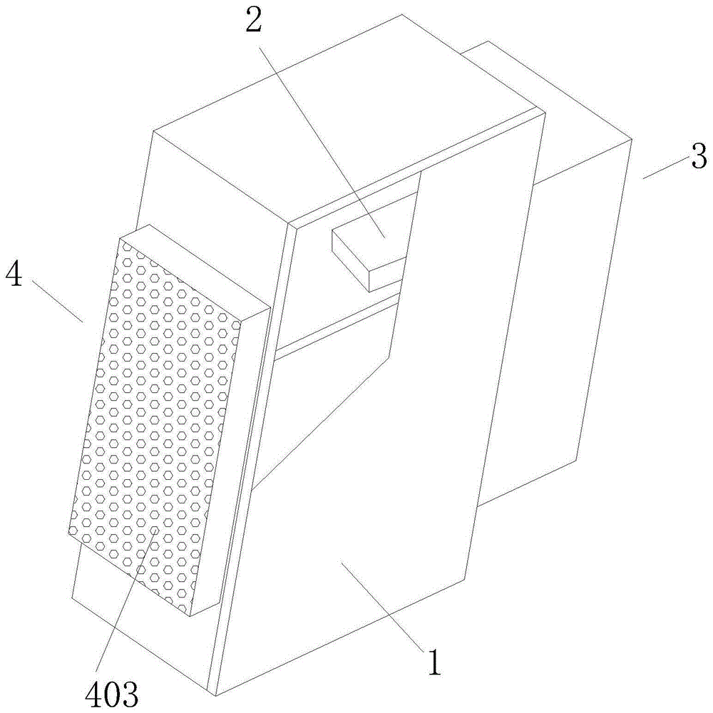
FIG. 1 is a schematic perspective view of the present invention;
FIG. 2 is a perspective view of the closure plate of the present invention;
FIG. 3 is a schematic view of the inner side of the air cooling mechanism according to the present invention;
FIG. 4 is a schematic view of the external three-dimensional structure of the air cooling mechanism of the present invention;
FIG. 5 is a cross-sectional view of the quick release assembly of the present invention;
FIG. 6 is a schematic view of a partial perspective structure of an air duct according to the present invention;
FIG. 7 is a schematic cross-sectional side view of the dust collecting mechanism of the present invention.
Wherein: 1. a wire inlet cabinet body; 2. a temperature sensor; 3. an air cooling mechanism; 301. an air duct; 302. a wind screen frame; 303. a quick release assembly; 3031. inserting holes; 3032. a plug rod; 3033. a bullet cavity; 3034. a resisting block; 3035. a spring; 304. a fan frame; 305. a fan; 4. a dust collecting mechanism; 401. a dust removal cavity; 402. a dust collecting concave plate; 403. an air outlet; 404. dust filtration cotton; 405. scraping dust strips; 406. a chute; 407. a slide bar; 409. closing the plate; 410. u-shaped guide rail bar.
Detailed Description
The technical solutions in the embodiments of the present invention will be clearly and completely described below with reference to the drawings in the embodiments of the present invention, and it is obvious that the described embodiments are only a part of the embodiments of the present invention, and not all of the embodiments. All other embodiments, which can be derived by a person skilled in the art from the embodiments given herein without making any creative effort, shall fall within the protection scope of the present invention.
Example one
The embodiment is a specific implementation mode of an incoming line cabinet with an automatic temperature adjusting function in the cabinet.
Referring to fig. 1-7, an incoming line cabinet with an automatic temperature adjusting function inside a cabinet comprises an incoming line cabinet body 1 and a temperature sensor 2, wherein the temperature sensor 2 is fixedly connected inside the incoming line cabinet body 1, an air cooling mechanism 3 is arranged inside the incoming line cabinet body 1, and a dust collecting mechanism 4 is further arranged inside the incoming line cabinet body 1;
the air cooling mechanism 3 comprises an air pipe 301, an air net frame 302 is arranged on one side of the air pipe 301, a quick-release assembly 303 is arranged between the air pipe 301 and the air net frame 302, the air pipe 301 is movably connected with the air net frame 302 through the quick-release assembly 303, a fan frame 304 is fixedly connected inside the air net frame 302, and a fan 305 is fixedly connected inside the fan frame 304;
dust collection mechanism 4 includes dust removal chamber 401, and the inside of dust removal chamber 401 articulates there is collection dirt concave 402, has seted up a plurality of exhaust vent 403 on the lateral wall of collection dirt concave 402, and the inside fixedly connected with of collection dirt concave 402 filters dirt cotton 404, and the inside of collection dirt concave 402 is provided with in the lateral wall that filters dirt cotton 404 scrapes dirt strip 405.
Through the technical scheme, electric connection between temperature sensor 2 and the fan 305, respond to the internal temperature of inlet wire cabinet 1 through temperature sensor 2, when the internal high temperature of inlet wire cabinet 1, start fan 305, fan 305 is to the internal each circuit of inlet wire cabinet 1 and blow the cooling, the dust of carrying of blowing can be blown to on the dirt filtering cotton 404, dirt filtering cotton 404 is held back the dust in with gas, make the dust adhere to on the dirt filtering cotton 404, exhaust vent 403 supplies the air current circulation, after the dust is concentrated to certain degree on dirt filtering cotton 404, open collection dirt concave plate 402, scrape down with the dust of scraping on dirt strip 405 with dirt filtering cotton 404, thereby carry out centralized clearance to the dust, prevent that the dust from wafting the interior circuit operation of secondary influence inlet wire cabinet 1, guarantee inlet wire cabinet 1 circuit operation reliable and stable.
Specifically, tuber pipe 301 fixed connection is on the lateral wall of the inlet wire cabinet body 1, and tuber pipe 301 communicates with each other with the inlet wire cabinet body 1.
Through the technical scheme, the air pipe 301 is used for inducing air to enter the inlet wire cabinet body 1.
Specifically, the outer side wall of the wind net frame 302 is matched with the inner side wall of the opening of the wind pipe 301, and the wind net frame 302 is located inside the inlet wire cabinet body 1.
Specifically, quick detach subassembly 303 includes plug jack 3031 and plug rod 3032, and plug jack 3031 and plug rod 3032 all are provided with four, and four plug jack 3031 are seted up respectively and are close to both ends position department on two opposite faces of the inside wall of tuber pipe 301, and four plug rod 3032 are close to both ends position department on two faces that deviate from each other on the lateral wall of wind screen frame 302 respectively swing joint in four plug rod 3032, and plug jack 3031 pegs graft with plug rod 3032 each other.
Through above-mentioned technical scheme, because fan 305 needs uninterrupted operation, in order to guarantee its stability, need regularly overhaul it and maintain, consequently, in order to overhaul the maintenance for the convenience, carry out swing joint through spliced eye 3031 and bayonet pole 3032 between tuber pipe 301 and the air mesh frame 302, make things convenient for the dismouting, raise the efficiency.
Specifically, the bullet chamber 3033 has all been seted up near four position departments of pegging graft pole 3032 on the lateral wall of wind screen frame 302, and four one end of pegging graft pole 3032 is pegged graft respectively in four inside of bullet chamber 3033, and four other ends of pegging graft pole 3032 extend in four outside of bullet chamber 3033.
Specifically, one end of each of the four insertion rods 3032, which is located in the spring cavity 3033, is fixedly connected with a resisting block 3034, the resisting block 3034 is slidably connected with the spring cavity 3033, a spring 3035 is sleeved on the outer side wall of the insertion rod 3032, and the spring 3035 is located inside the spring cavity 3033.
Through the technical scheme, the spring 3035 is in a contraction state in a natural state, the spring 3035 is fixedly connected with the abutting block 3034, the spring 3035 pulls the abutting block 3034 to move towards the outside of the spring cavity 3033, and the spring 3034 moves along with the insertion rod 3032 fixed by the abutting block 3034, so that the clamping state is automatically kept with the insertion hole 3031, when the disassembly is needed, the insertion rod 3032 is only required to be pressed, the spring 3035 is enabled to extend, and the insertion rod 3032 is enabled to withdraw from the insertion hole 3031, and the disassembly is convenient and rapid.
Specifically, the dust removal cavity 401 is opened on the outer side wall of the inlet wire cabinet body 1 and on the opposite surface of the fan 305, the dust collection concave plate 402 protrudes outside the outer side wall of the inlet wire cabinet body 1, and the dust collection concave plate 402 is connected with the dust filter cotton 404 through a bolt.
Through the technical scheme, the dust filter cotton 404 can be disassembled and assembled on the dust collection concave plate 402 at any time through the bolts, so that the dust filter cotton 404 is convenient to replace and clean.
Specifically, two opposite surfaces of the inner side wall of the dust collection concave plate 402 are provided with sliding grooves 406, the two sliding grooves 406 are fixedly connected with sliding rods 407, and two ends of the dust scraping strip 405 are connected with the two sliding rods 407 in a sliding manner.
Through above-mentioned technical scheme, when needing to clear up the cotton 404 of dirt filtrating, open collection dirt concave 402, promote from top to bottom and scrape dirt strip 405, scrape dirt strip 405 surface and should contact with the surface of the cotton 404 of dirt filtrating, can scrape the cotton 404 surface of dirt filtrating when promoting from top to bottom and scraping dirt strip 405, convenient and fast, quick completion is cleared up the cotton 404 surface of dirt filtrating.
Specifically, dust collecting mechanism 4 still includes shrouding 409, and shrouding 409 sets up in the one side that is close to dust removal cavity 401 on the inside wall of the inlet wire cabinet body 1, two U-shaped guide rail strips 410 of fixedly connected with on the inside wall of the inlet wire cabinet body 1, and shrouding 409 sets up between two U-shaped guide rail strips 410, sliding connection between shrouding 409 and two U-shaped guide rail strips 410.
Through above-mentioned technical scheme, in order to prevent that the dust from scattering when clearing up the cotton 404 surface of straining dust and getting into the internal influence circuit of the cabinet body inlet wire cabinet of inlet wire, during the clearance, open behind the collection dirt concave 402, promote shrouding 409 for shrouding 409 slides to dust removal chamber 401 along U-shaped guide rail strip 410 and locates, carries out the shutoff to dust removal chamber 401, prevents that the dust from getting into the cabinet body inlet wire cabinet of inlet wire cabinet body 1 internally, improves dust removal effect.
Example two
The embodiment is a specific implementation mode of the air cooling mechanism 3 of the inlet cabinet with the automatic temperature adjustment function inside the cabinet.
The utility model provides an in-box temperature automatically regulated's inlet wire cabinet's air-cooled mechanism 3, includes tuber pipe 301, and one side of tuber pipe 301 is provided with wind net frame 302, is provided with quick detach subassembly 303 between tuber pipe 301 and the wind net frame 302, and swing joint between tuber pipe 301 passes through quick detach subassembly 303 and the wind net frame 302, the inside fixedly connected with fan frame 304 of wind net frame 302, the inside fixedly connected with fan 305 of fan frame 304.
Through above-mentioned technical scheme, electric connection between temperature sensor 2 and the fan 305, through the internal temperature of the cabinet of the inlet wire cabinet of 2 response of temperature sensor, when the internal high temperature of the cabinet of inlet wire cabinet 1, start fan 305, fan 305 blows the cooling to each circuit in the cabinet of the inlet wire cabinet 1.
EXAMPLE III
The embodiment is a specific implementation mode of a dust collecting mechanism 4 of a wire inlet cabinet with an automatic temperature adjusting function in the cabinet.
The utility model provides an in-box temperature automatically regulated's inlet wire cabinet's collection dirt mechanism 4, includes dust removal chamber 401, and dust removal chamber 401's inside articulates there is collection dirt concave plate 402, has seted up a plurality of exhaust vent 403 on collection dirt concave plate 402's the lateral wall, and the inside fixedly connected with of collection dirt concave plate 402 strains the cotton 404 of dirt, and the inside of collection dirt concave plate 402 is provided with in the lateral wall of straining the cotton 404 of dirt and scrapes dirt strip 405.
Through above-mentioned technical scheme, the dust of carrying of blowing can be blown to on the dirt cotton 404, dirt cotton 404 is held back with the dust in the gas to the dirt cotton 404, make the dust attach to on the dirt cotton 404, the exhaust vent 403 supplies the air current circulation, after the dust concentrates on certain degree on dirt cotton 404, open collection dirt concave plate 402, scrape down with scraping the dust on dirt cotton 404 of dirt strip 405, thereby carry out centralized clearance to the dust, prevent that the dust from wandering the interior circuit operation of secondary influence inlet wire cabinet body 1, guarantee that the circuit operation is reliable and stable in inlet wire cabinet body 1.
When using, through the internal temperature of the inlet wire cabinet of temperature sensor 2 response 1, when the internal high temperature of inlet wire cabinet, start fan 305, fan 305 is to each circuit of the internal 1 of inlet wire cabinet and is bloied the cooling, the dust that the carrying of blowing can be blown to on the dirt filtrating cotton 404, dirt filtrating cotton 404 is held back with the dust in the gas, make the dust attach to on the dirt filtrating cotton 404, exhaust vent 403 supplies the air current circulation, after the dust concentrates to the certain degree on dirt filtrating cotton 404, open collection dirt concave plate 402, scrape down with the dust of scraping dirt strip 405 on the dirt filtrating cotton 404, can.
Although embodiments of the present invention have been shown and described, it will be appreciated by those skilled in the art that changes, modifications, substitutions and alterations can be made in these embodiments without departing from the principles and spirit of the invention, the scope of which is defined in the appended claims and their equivalents.

Claims (9)

1.一种箱内温度自动调节的进线柜,包括进线柜体(1)和温度传感器(2),其特征在于:所述温度传感器(2)固定连接于进线柜体(1)的内部,所述进线柜体(1)的内部设置有风冷机构(3),所述进线柜体(1)的内部还设置有集尘机构(4);1. An incoming line cabinet with automatic temperature adjustment in a box, comprising an incoming line cabinet body (1) and a temperature sensor (2), characterized in that: the temperature sensor (2) is fixedly connected to the incoming line cabinet body (1) The inside of the wire inlet cabinet (1) is provided with an air cooling mechanism (3), and the inside of the wire inlet cabinet (1) is also provided with a dust collection mechanism (4); 所述风冷机构(3)包括风管(301),所述风管(301)的一侧设置有风网框(302),所述风管(301)与风网框(302)之间设置有快拆组件(303),所述风管(301)通过快拆组件(303)与风网框(302)之间活动连接,所述风网框(302)的内部固定连接有风扇框架(304),所述风扇框架(304)的内部固定连接有风扇(305);The air cooling mechanism (3) includes an air duct (301), and an air mesh frame (302) is arranged on one side of the air duct (301), and a space between the air duct (301) and the air mesh frame (302) is provided. A quick release assembly (303) is provided, and the air duct (301) is movably connected with the air mesh frame (302) through the quick release assembly (303), and the interior of the air mesh frame (302) is fixedly connected with a fan frame (304), a fan (305) is fixedly connected inside the fan frame (304); 所述集尘机构(4)包括除尘腔(401),所述除尘腔(401)的内部铰接有集尘凹板(402),所述集尘凹板(402)的外侧壁上开设有若干个出风孔(403),所述集尘凹板(402)的内部固定连接有滤尘棉(404),所述集尘凹板(402)的内部于滤尘棉(404)的外侧壁设置有刮尘条(405)。The dust collecting mechanism (4) includes a dust collecting cavity (401), and a dust collecting concave plate (402) is hinged inside the dust collecting cavity (401), and a plurality of dust collecting concave plates (402) are opened on the outer side wall of the dust collecting concave plate (402). There are two air outlet holes (403), a dust filter cotton (404) is fixedly connected to the inside of the dust collecting concave plate (402), and the inside of the dust collecting concave plate (402) is provided with a dust filter cotton (404) on the outer side wall of the dust filter cotton (404). Scraper strip (405). 2.根据权利要求1所述的一种箱内温度自动调节的进线柜,其特征在于:所述风管(301)固定连接于进线柜体(1)的外侧壁上,所述风管(301)与进线柜体(1)相通。2 . The inlet cabinet with automatic temperature adjustment in the box according to claim 1 , wherein the air duct ( 301 ) is fixedly connected to the outer side wall of the inlet cabinet ( 1 ), and the air duct ( 301 ) The pipe (301) communicates with the incoming line cabinet (1). 3.根据权利要求2所述的一种箱内温度自动调节的进线柜,其特征在于:所述风网框(302)的外侧壁与风管(301)的开口处内侧壁相适配,所述风网框(302)位于进线柜体(1)的内部。3. The wire inlet cabinet with automatic temperature adjustment in the box according to claim 2, characterized in that: the outer side wall of the air mesh frame (302) is adapted to the inner side wall of the opening of the air duct (301) , the wind screen frame (302) is located inside the incoming line cabinet (1). 4.根据权利要求3所述的一种箱内温度自动调节的进线柜,其特征在于:所述快拆组件(303)包括插接孔(3031)和插接杆(3032),所述插接孔(3031)和插接杆(3032)均设置有四个,四个所述插接孔(3031)分别开设于风管(301)的内侧壁两个相对面上靠近两端位置处,四个所述插接杆(3032)分别活动连接于风网框(302)的外侧壁上两个相背离的面上靠近两端位置处,所述插接孔(3031)与插接杆(3032)相互插接。4 . The cable entry cabinet with automatic temperature adjustment in the box according to claim 3 , wherein the quick release assembly ( 303 ) comprises an insertion hole ( 3031 ) and an insertion rod ( 3032 ), and the Four insertion holes (3031) and insertion rods (3032) are each provided, and the four insertion holes (3031) are respectively opened on two opposite surfaces of the inner side wall of the air duct (301) at positions close to both ends , the four plugging rods (3032) are respectively movably connected to the two opposite faces on the outer side wall of the wind screen frame (302) near the two ends, the plugging holes (3031) and the plugging rods (3032) are plugged into each other. 5.根据权利要求4所述的一种箱内温度自动调节的进线柜,其特征在于:所述风网框(302)的外侧壁上靠近四个插接杆(3032)的位置处均开设有弹腔(3033),四个所述插接杆(3032)的一端分别插接于四个弹腔(3033)的内部,四个所述插接杆(3032)的另一端延伸于四个弹腔(3033)的外部。5 . The wire inlet cabinet with automatic temperature adjustment in the box according to claim 4 , wherein the outer side walls of the air mesh frame ( 302 ) are at positions close to the four plug-in rods ( 3032 ). 6 . There are elastic cavities (3033), one end of the four insertion rods (3032) is respectively inserted into the interior of the four elastic cavities (3033), and the other ends of the four insertion rods (3032) extend to four Outside of each bullet cavity (3033). 6.根据权利要求5所述的一种箱内温度自动调节的进线柜,其特征在于:四个所述插接杆(3032)上位于弹腔(3033)内的一端均固定连接有抵块(3034),所述抵块(3034)与弹腔(3033)滑动连接,所述插接杆(3032)的外侧壁上套设有弹簧(3035),所述弹簧(3035)位于弹腔(3033)的内部。6 . The wire inlet cabinet with automatic temperature adjustment in the box according to claim 5 , wherein one end of the four plug-in rods ( 3032 ) located in the elastic cavity ( 3033 ) is fixedly connected with a contactor. 7 . A block (3034), the abutting block (3034) is slidably connected with the elastic cavity (3033), and a spring (3035) is sleeved on the outer side wall of the insertion rod (3032), and the spring (3035) is located in the elastic cavity (3033). 7.根据权利要求1所述的一种箱内温度自动调节的进线柜,其特征在于:所述除尘腔(401)开设于进线柜体(1)的外侧壁上与风扇(305)相对面上,所述集尘凹板(402)外凸于进线柜体(1)的外侧壁外部,所述集尘凹板(402)与滤尘棉(404)之间通过螺栓连接。7. The wire inlet cabinet with automatic temperature adjustment in the box according to claim 1, characterized in that: the dust removal chamber (401) is opened on the outer side wall of the wire inlet cabinet (1) and is connected to the fan (305) On the opposite side, the dust collecting concave plate (402) protrudes outside the outer side wall of the incoming cabinet (1), and the dust collecting concave plate (402) and the dust filter cotton (404) are connected by bolts. 8.根据权利要求1所述的一种箱内温度自动调节的进线柜,其特征在于:所述集尘凹板(402)的内侧壁两个相对面上均开设有滑槽(406),两个所述滑槽(406)的内部均固定连接有滑杆(407),所述刮尘条(405)的两端与两个滑杆(407)之间滑动连接。8 . The wire inlet cabinet with automatic temperature adjustment in the box according to claim 1 , wherein a chute ( 406 ) is provided on both opposite surfaces of the inner side wall of the dust collecting concave plate ( 402 ). 9 . , the interiors of the two sliding grooves (406) are fixedly connected with sliding rods (407), and the two ends of the dust scraping strip (405) are slidably connected with the two sliding rods (407). 9.根据权利要求8所述的一种箱内温度自动调节的进线柜,其特征在于:所述集尘机构(4)还包括封板(409),所述封板(409)设置于进线柜体(1)的内侧壁上靠近除尘腔(401)的一侧,所述进线柜体(1)的内侧壁上固定连接有两个U形导轨条(410),所述封板(409)设置于两个U形导轨条(410)之间,所述封板(409)与两个U形导轨条(410)之间滑动连接。9 . The wire entry cabinet with automatic temperature adjustment in the box according to claim 8 , wherein the dust collecting mechanism ( 4 ) further comprises a sealing plate ( 409 ), and the sealing plate ( 409 ) is arranged on the The inner side wall of the incoming cabinet (1) is on the side close to the dust removal chamber (401), and two U-shaped guide rails (410) are fixedly connected to the inner wall of the incoming cabinet (1). The plate (409) is arranged between the two U-shaped guide rails (410), and the sealing plate (409) is slidably connected with the two U-shaped guide rails (410).
CN202210206369.2A 2022-03-01 2022-03-01 Inlet wire cabinet with automatic temperature adjustment in box Active CN114512914B (en)

Priority Applications (1)

Application Number Priority Date Filing Date Title
CN202210206369.2A CN114512914B (en) 2022-03-01 2022-03-01 Inlet wire cabinet with automatic temperature adjustment in box

Applications Claiming Priority (1)

Application Number Priority Date Filing Date Title
CN202210206369.2A CN114512914B (en) 2022-03-01 2022-03-01 Inlet wire cabinet with automatic temperature adjustment in box

Publications (2)

Publication Number Publication Date
CN114512914A true CN114512914A (en) 2022-05-17
CN114512914B CN114512914B (en) 2026-03-03

Family

ID=81553969

Family Applications (1)

Application Number Title Priority Date Filing Date
CN202210206369.2A Active CN114512914B (en) 2022-03-01 2022-03-01 Inlet wire cabinet with automatic temperature adjustment in box

Country Status (1)

Country Link
CN (1) CN114512914B (en)

Citations (6)

* Cited by examiner, † Cited by third party
Publication number Priority date Publication date Assignee Title
CN212137069U (en) * 2020-06-12 2020-12-11 国网冀北电力有限公司技能培训中心 High tension switchgear dust removal heat abstractor
CN212851608U (en) * 2020-09-27 2021-03-30 无锡驰航鑫机械有限公司 Machine tool control cabinet radiator convenient to disassemble and maintain
CN214544141U (en) * 2020-12-29 2021-10-29 江苏阿诗特能源科技有限公司 Novel energy storage inverter
CN214754892U (en) * 2021-04-13 2021-11-16 青岛昭日电气有限公司 Improved dustproof drawer type low-voltage switch cabinet
CN215009102U (en) * 2021-06-18 2021-12-03 河南省垠兴电力设备有限公司 A 10kV intelligent switch cabinet
CN215528389U (en) * 2021-08-24 2022-01-14 国网河南省电力公司西华县供电公司 Power equipment cabinet with good heat dissipation performance

Patent Citations (6)

* Cited by examiner, † Cited by third party
Publication number Priority date Publication date Assignee Title
CN212137069U (en) * 2020-06-12 2020-12-11 国网冀北电力有限公司技能培训中心 High tension switchgear dust removal heat abstractor
CN212851608U (en) * 2020-09-27 2021-03-30 无锡驰航鑫机械有限公司 Machine tool control cabinet radiator convenient to disassemble and maintain
CN214544141U (en) * 2020-12-29 2021-10-29 江苏阿诗特能源科技有限公司 Novel energy storage inverter
CN214754892U (en) * 2021-04-13 2021-11-16 青岛昭日电气有限公司 Improved dustproof drawer type low-voltage switch cabinet
CN215009102U (en) * 2021-06-18 2021-12-03 河南省垠兴电力设备有限公司 A 10kV intelligent switch cabinet
CN215528389U (en) * 2021-08-24 2022-01-14 国网河南省电力公司西华县供电公司 Power equipment cabinet with good heat dissipation performance

Also Published As

Publication number Publication date
CN114512914B (en) 2026-03-03

Similar Documents

Publication Publication Date Title
CN108598894A (en) A kind of dustproof construction and its application method for power distribution cabinet
CN209329427U (en) A kind of power distribution cabinet of good heat dissipation effect
CN212137069U (en) High tension switchgear dust removal heat abstractor
CN210898073U (en) Dustproof high-low voltage switch cabinet
CN109526166A (en) One kind being convenient for clean electrical cabinet
CN114512914B (en) Inlet wire cabinet with automatic temperature adjustment in box
CN208586391U (en) A kind of dust exhaust apparatus of weaving loom
CN215185469U (en) Self-dedusting drawer of draw-out switch cabinet
CN212881477U (en) A dust removal device for electrical equipment
CN109600950A (en) A kind of artificial intelligence electrical control gear
CN209343892U (en) A kind of Multifunction transformer case
CN218924117U (en) Novel dust removal equipment for air treatment
CN216016040U (en) Movable high-voltage switch cabinet
CN208112076U (en) Dust-extraction unit and its circuit structure in a kind of switchgear
CN211579339U (en) A power distribution cabinet with good dustproof performance
CN209823142U (en) Environment-friendly high-low voltage power distribution cabinet structure
CN211209073U (en) A switchgear for electrical engineering
CN217009922U (en) Novel complete control cabinet for automatic control equipment
CN219144736U (en) A switch cabinet capable of automatic dust removal and cleaning
CN211151142U (en) Cubical switchboard convenient to installation
CN217362307U (en) High-low voltage switch cabinet with good heat dissipation effect
CN212085494U (en) Dustproof switch cabinet
CN218828665U (en) Take manual belt cleaning device's block terminal
CN215070912U (en) A new type of AC low-voltage switchgear
CN221928938U (en) An electrical control cabinet that is easy to clean

Legal Events

Date Code Title Description
PB01 Publication
PB01 Publication
SE01 Entry into force of request for substantive examination
GR01 Patent grant
GR01 Patent grant