CN114512285A - Horizontal enameling machine - Google Patents
Horizontal enameling machine Download PDFInfo
- Publication number
- CN114512285A CN114512285A CN202210170732.XA CN202210170732A CN114512285A CN 114512285 A CN114512285 A CN 114512285A CN 202210170732 A CN202210170732 A CN 202210170732A CN 114512285 A CN114512285 A CN 114512285A
- Authority
- CN
- China
- Prior art keywords
- channel
- water
- drying
- heating
- wire
- Prior art date
- Legal status (The legal status is an assumption and is not a legal conclusion. Google has not performed a legal analysis and makes no representation as to the accuracy of the status listed.)
- Granted
Links
- 238000004534 enameling Methods 0.000 title claims description 12
- 238000010438 heat treatment Methods 0.000 claims abstract description 118
- 238000001035 drying Methods 0.000 claims abstract description 87
- 238000005192 partition Methods 0.000 claims abstract description 30
- 230000005540 biological transmission Effects 0.000 claims abstract description 24
- 238000000137 annealing Methods 0.000 claims abstract description 19
- XLYOFNOQVPJJNP-UHFFFAOYSA-N water Substances O XLYOFNOQVPJJNP-UHFFFAOYSA-N 0.000 claims description 145
- RYGMFSIKBFXOCR-UHFFFAOYSA-N Copper Chemical compound [Cu] RYGMFSIKBFXOCR-UHFFFAOYSA-N 0.000 claims description 41
- 238000001816 cooling Methods 0.000 claims description 41
- 229910052802 copper Inorganic materials 0.000 claims description 33
- 239000010949 copper Substances 0.000 claims description 33
- 230000007246 mechanism Effects 0.000 claims description 29
- 239000003960 organic solvent Substances 0.000 claims description 22
- 238000010422 painting Methods 0.000 claims description 22
- 238000003825 pressing Methods 0.000 claims description 19
- 238000010521 absorption reaction Methods 0.000 claims description 18
- 238000005096 rolling process Methods 0.000 claims description 17
- 229920000742 Cotton Polymers 0.000 claims description 16
- 239000000463 material Substances 0.000 claims description 15
- 238000000034 method Methods 0.000 claims description 14
- 230000008569 process Effects 0.000 claims description 13
- 238000007084 catalytic combustion reaction Methods 0.000 claims description 9
- 239000002904 solvent Substances 0.000 claims description 8
- 238000005485 electric heating Methods 0.000 claims description 6
- 230000000149 penetrating effect Effects 0.000 claims description 6
- 238000009434 installation Methods 0.000 claims description 5
- 238000007791 dehumidification Methods 0.000 claims description 4
- 230000003014 reinforcing effect Effects 0.000 claims description 4
- 238000001704 evaporation Methods 0.000 claims description 3
- 238000001125 extrusion Methods 0.000 claims description 3
- 238000009423 ventilation Methods 0.000 claims description 2
- 239000004576 sand Substances 0.000 claims 2
- 238000005253 cladding Methods 0.000 claims 1
- 238000004134 energy conservation Methods 0.000 abstract description 3
- 230000009467 reduction Effects 0.000 abstract description 2
- 239000002699 waste material Substances 0.000 abstract description 2
- 230000000694 effects Effects 0.000 description 8
- 239000007789 gas Substances 0.000 description 4
- 238000006555 catalytic reaction Methods 0.000 description 3
- 230000008859 change Effects 0.000 description 3
- 229910052782 aluminium Inorganic materials 0.000 description 2
- XAGFODPZIPBFFR-UHFFFAOYSA-N aluminium Chemical compound [Al] XAGFODPZIPBFFR-UHFFFAOYSA-N 0.000 description 2
- 239000003054 catalyst Substances 0.000 description 2
- 238000009826 distribution Methods 0.000 description 2
- 238000005265 energy consumption Methods 0.000 description 2
- 238000001914 filtration Methods 0.000 description 2
- 229910000510 noble metal Inorganic materials 0.000 description 2
- 239000003973 paint Substances 0.000 description 2
- 239000002966 varnish Substances 0.000 description 2
- 210000003298 dental enamel Anatomy 0.000 description 1
- 230000007613 environmental effect Effects 0.000 description 1
- 230000004907 flux Effects 0.000 description 1
- 238000004519 manufacturing process Methods 0.000 description 1
- 229920000642 polymer Polymers 0.000 description 1
- 239000000126 substance Substances 0.000 description 1
- 235000021419 vinegar Nutrition 0.000 description 1
- 239000000052 vinegar Substances 0.000 description 1
- 239000002912 waste gas Substances 0.000 description 1
- 238000005491 wire drawing Methods 0.000 description 1
Images




Classifications
-
- H—ELECTRICITY
- H01—ELECTRIC ELEMENTS
- H01B—CABLES; CONDUCTORS; INSULATORS; SELECTION OF MATERIALS FOR THEIR CONDUCTIVE, INSULATING OR DIELECTRIC PROPERTIES
- H01B13/00—Apparatus or processes specially adapted for manufacturing conductors or cables
- H01B13/30—Drying; Impregnating
-
- H—ELECTRICITY
- H01—ELECTRIC ELEMENTS
- H01B—CABLES; CONDUCTORS; INSULATORS; SELECTION OF MATERIALS FOR THEIR CONDUCTIVE, INSULATING OR DIELECTRIC PROPERTIES
- H01B13/00—Apparatus or processes specially adapted for manufacturing conductors or cables
- H01B13/0036—Details
-
- H—ELECTRICITY
- H01—ELECTRIC ELEMENTS
- H01B—CABLES; CONDUCTORS; INSULATORS; SELECTION OF MATERIALS FOR THEIR CONDUCTIVE, INSULATING OR DIELECTRIC PROPERTIES
- H01B13/00—Apparatus or processes specially adapted for manufacturing conductors or cables
- H01B13/06—Insulating conductors or cables
- H01B13/065—Insulating conductors with lacquers or enamels
-
- H—ELECTRICITY
- H01—ELECTRIC ELEMENTS
- H01B—CABLES; CONDUCTORS; INSULATORS; SELECTION OF MATERIALS FOR THEIR CONDUCTIVE, INSULATING OR DIELECTRIC PROPERTIES
- H01B13/00—Apparatus or processes specially adapted for manufacturing conductors or cables
- H01B13/06—Insulating conductors or cables
- H01B13/16—Insulating conductors or cables by passing through or dipping in a liquid bath; by spraying
- H01B13/165—Insulating conductors or cables by passing through or dipping in a liquid bath; by spraying by spraying
-
- Y—GENERAL TAGGING OF NEW TECHNOLOGICAL DEVELOPMENTS; GENERAL TAGGING OF CROSS-SECTIONAL TECHNOLOGIES SPANNING OVER SEVERAL SECTIONS OF THE IPC; TECHNICAL SUBJECTS COVERED BY FORMER USPC CROSS-REFERENCE ART COLLECTIONS [XRACs] AND DIGESTS
- Y02—TECHNOLOGIES OR APPLICATIONS FOR MITIGATION OR ADAPTATION AGAINST CLIMATE CHANGE
- Y02P—CLIMATE CHANGE MITIGATION TECHNOLOGIES IN THE PRODUCTION OR PROCESSING OF GOODS
- Y02P70/00—Climate change mitigation technologies in the production process for final industrial or consumer products
- Y02P70/50—Manufacturing or production processes characterised by the final manufactured product
Landscapes
- Engineering & Computer Science (AREA)
- Manufacturing & Machinery (AREA)
- Drying Of Solid Materials (AREA)
Abstract
The invention discloses a horizontal enamelling machine, which comprises a paying-off wheel, an annealing furnace, an enamelling device, a drying device and a wire collecting device, wherein the drying device comprises a drying rack, a drying furnace is arranged on the drying rack, the drying furnace comprises a furnace body, a heating channel for enamelled wires to pass through is arranged below the furnace body, the heating channel is divided into a first heat flow cavity, a second heat flow cavity and a uniform flow cavity by a first partition plate and a second partition plate, a plurality of first overflowing holes are formed in the first partition plate, and a plurality of second overflowing holes are formed in the second partition plate; the heating chamber is arranged at the position above the heating channel in the furnace body, the uniform flow cavity of the heating channel is communicated with the heating chamber through a backflow channel, and the heating chamber is provided with a forward circulation channel communicated with the uniform flow cavity of the heating channel relative to the head end of the transmission direction of the enameled wire and a reverse circulation channel communicated with the first overflowing cavity of the heating channel relative to the tail end of the transmission direction of the enameled wire. The invention has the advantages of energy conservation and emission reduction, and can reduce the processing cost of enterprises while avoiding resource waste.
Description
Technical Field
The invention relates to the field of environmental protection chemical industry, in particular to a horizontal enamelling machine.
Background
The horizontal enameling machine is important equipment for producing enameled wires in the electromagnetic wire industry, and has the function of uniformly wrapping a layer of insulating polymer vinegar paint on the outer surface of a processed copper wire (or aluminum wire), and the horizontal enameling machine generally processes the enameled wires with the diameter of 0.011 mm-0.80 mm.
The production process of the enameled wire generally comprises paying off, annealing, painting, drying, cooling, taking up and the like, and the processes are all realized on an enamelling machine, so that the outer surface of a processed copper wire (or aluminum wire) can be uniformly coated with a layer of insulating paint. Copper line need carry out the stoving through the drying oven after the japanning, and traditional drying oven generally adopts the electrical heating mode, and this kind of heating need consume a large amount of electric energy, improves the processing cost of enterprise when causing the wasting of resources.
Disclosure of Invention
The invention aims to provide a horizontal enamelling machine which has the advantages of energy conservation and emission reduction, and can reduce the processing cost of enterprises while avoiding resource waste.
In order to achieve the purpose, the invention provides the following technical scheme: the horizontal enamelling machine comprises an paying-off wheel, an annealing furnace, a painting device, a drying device and a wire collecting device, wherein copper wires paid off by the paying-off wheel are sequentially annealed, painted and dried by the annealing furnace, the painting device and the drying device, and finally are collected by the wire collecting device; the drying device comprises a drying rack, a drying furnace is arranged on the drying rack, the drying furnace comprises a furnace body, a heating channel for the enameled wire to pass through is arranged below the furnace body, the heating channel is divided into a first heat flow cavity, a second heat flow cavity and a uniform flow cavity through a first partition plate and a second partition plate, a plurality of first overflowing holes used for communicating the first heat flow cavity with the second heat flow cavity are formed in the first partition plate, a plurality of second overflowing holes used for communicating the second heat flow cavity with the uniform flow cavity are formed in the second partition plate, and the orthographic projection of the first overflowing holes on the second partition plate is not overlapped with the second overflowing holes; a heating chamber is arranged above the heating channel in the furnace body, an exhaust port is arranged above the heating chamber, a uniform flow cavity of the heating channel is communicated with the heating chamber through a backflow channel, the heating chamber is provided with a forward circulation channel communicated with the uniform flow cavity of the heating channel relative to the head end of the enameled wire transmission direction and a reverse circulation channel communicated with the first overflowing cavity of the heating channel relative to the tail end of the enameled wire transmission direction, the width of the reverse circulation channel is gradually increased in the transmission direction of hot air, the heating chamber, the forward circulation channel and the heating channel form forward solvent circulation for evaporating organic solvent carried by the enameled wire and sending the organic solvent into the heating chamber, the reverse circulation channel, the heating channel and the backflow channel form reverse heating circulation for carrying out hot baking on the enameled wire by the hot air, and the heating chamber is provided with a circulation mechanism for driving air flow to continuously circulate along the forward solvent circulation and the reverse heating circulation, the heating chamber is sequentially provided with a preheating part for preheating the organic solvent and a catalytic combustion part for catalytically combusting the preheated organic solvent, and the preheating part comprises an electric heating device and a heat exchanger for exchanging heat with the catalytic combustion part.
By adopting the technical scheme, the enamelled wire is painted, the surface of the enamelled wire is often adhered with the organic solvent, the organic solvent is required to be filtered before exhaust gas is exhausted to the outside, the organic solvent is reasonably utilized to be catalytically heated, the filtering cost is saved, energy is saved, and the electric energy effect is reduced, when the enamelled wire enters a furnace body through an inlet of a heating channel, the organic solvent carried by the enamelled wire is evaporated by airflow in a forward solvent circulation mode and is sent into a heating chamber, the catalysis is carried out by a catalyst (noble metal) after the temperature required by catalysis is reached in the heating chamber, the formed heat enters a reverse heating circulation from hot airflow, the hot airflow of the enamelled wire transmitted along the heating channel is formed, the hot baking function is realized, then, the first preheating temperature of the organic solvent in the heating chamber is realized by an electric heating device, and then the heat exchange with a catalytic combustion part is realized by a heat exchanger, follow-up need not electric heater unit and participates in, thereby realize energy-conservation, and the heating channel is separated into first heat flow chamber through first baffle and second baffle, the three cavity in second heat flow chamber and uniform flow chamber, the enameled wire is passed from the uniform flow chamber, because the orthographic projection of first discharge orifice on the second baffle on the first baffle is not overlapped with the second discharge orifice, consequently the hot gas flow passes first baffle and is dispersed by the resistance of second baffle after entering into second heat flow chamber, make the hot gas flow more even, later the hot gas flow passes the second baffle again and enters into the uniform flow chamber and heat the stoving to the enameled wire, can keep the heat even, avoided vertical difference in temperature to cause the not good condition of enameled wire stoving effect to take place, thereby promote the quality of final enameled wire finished product.
The enameled wire conveying device is further provided with a plurality of first overflowing holes which are distributed on the first partition plate in a mode that intervals gradually increase along the enameled wire conveying direction, and a plurality of second overflowing holes which are uniformly distributed on the second partition plate.
Through adopting above-mentioned technical scheme, first baffle carries out first heat reposition of redundant personnel process for the heat flow that gets into the second heat flow intracavity distributes evenly, and the second baffle further carries out the second and says heat reposition of redundant personnel process, makes the heat flow that gets into the uniform flow intracavity distribute more evenly, thereby promotes the stoving effect of enameled wire.
The invention is further provided that an inverted V-shaped guide plate is arranged at the bottom of the uniform flow cavity of the heating channel, and the inverted V-shaped guide plate comprises a first guide part for guiding hot air flow entering the uniform flow cavity in the reverse heating circulation process to the backflow channel and a second guide part for guiding hot air flow entering the heating channel in the forward heating circulation process to the backflow channel.
By adopting the technical scheme, hot air flow in the heating channel in the forward heating circulation and hot air flow in the heating channel in the reverse heating circulation can be effectively guided into the backflow channel, so that effective circulation of the hot air flow is realized, the heat utilization rate of equipment is improved, and energy consumption is reduced.
The invention is further arranged in such a way that the furnace body is respectively provided with a connecting bin at the two sides of the heating chamber, a plurality of heat collecting pipes are connected between the two connecting bins, the plurality of heat collecting pipes are arranged in the heating chamber, and the parts of the two connecting bins outside the furnace body are respectively connected with a first pipeline and a second pipeline.
Through adopting above-mentioned technical scheme, because many places of enamelling machine device all need heat, add the heating pipe and can effectively utilize the heat in the heating chamber, take away local heat through first pipeline and second pipeline, regard local heat as the heat supply of other devices, simplify the heat supply structure of equipment, further improve energy-conserving effect.
The invention is further provided that a plurality of reinforcing plates are distributed on the outer wall of the heating channel and the outer wall of the reverse circulation channel along the respective path directions.
Through adopting above-mentioned technical scheme, can promote the structural strength who heats passageway and reverse circulation passageway, the material takes place to warp when avoiding the temperature change.
The circulating mechanism further comprises a circulating fan fixed on the furnace body, wherein the circulating fan is positioned at the intersection of the forward circulating channel and the reverse circulating channel and forms negative pressure for guiding airflow to the forward circulating channel and the reverse circulating channel.
Through adopting above-mentioned technical scheme, set up circulating fan and adjust it to the intersection of forward circulation passageway and reverse circulation passageway, with the air current to forward circulation passageway and reverse circulation passageway guide simultaneously, guarantee the retrenchment nature of structure.
The invention is further arranged in that a cooling device for cooling the copper wires and a drying device for dehumidifying the copper wires are sequentially arranged between the annealing furnace and the painting device, the cooling device comprises a water cooling mechanism and an air cooling mechanism, the water cooling mechanism comprises a lower water tank, an upper water tank and a water pump, one side of the upper water tank close to the painting device is provided with a plurality of wire passing holes for the copper wires to pass through, a water return frame is arranged on the upper water tank close to the painting device, one side of the water return frame close to the painting device is provided with a water return port along the length direction, the top of the water return frame is provided with a water inlet port communicated with the water return port, the inlet end of the water pump is arranged in the lower water tank, the outlet end of the water pump is communicated with the water inlet port through a water pipe, the bottom in the upper water tank is also provided with a water return platform, the part of the water return platform close to the annealing furnace is provided with a water outlet communicated with the lower water tank, the water outlet is obliquely arranged from top to bottom towards the painting device, and one side of the water return platform, which is close to the painting device, is provided with a flow guide inclined plane; the air cooling mechanism is including setting up the air-cooled frame on the water tank down, install the forced air cooling case on the air-cooled frame, the one end of forced air cooling case is connected with the air-supply line, the forced air cooling case runs through along length direction and is provided with a plurality of pipes that are used for the wire to pass, pipe both ends are threaded connection one respectively and are used for supporting the stop nut in forced air cooling case both sides, a plurality of wind holes have been seted up to the pipe lateral part, still be equipped with the guide wheel frame on the water tank down, install first pivot on the guide wheel frame, rotate on the first pivot and install the wire wheel.
Through adopting above-mentioned technical scheme, can effectively cool down, wash and dry to the copper line after the annealing to guarantee the quality of follow-up copper line japanning.
The invention is further provided with a water absorption mechanism which is arranged on the lower water tank and is close to the thread passing hole of the upper water tank, the water absorption mechanism comprises two mounting brackets which are symmetrically arranged on two sides of the lower water tank, a first water absorption roller is rotationally connected between the two mounting brackets through a second rotating shaft, a first driving motor is arranged on one mounting bracket, a motor shaft of the first driving motor is in linkage connection with one end of the second rotating shaft, the side part of the first water absorption roller is coated with a first water absorption cotton sleeve, the top part of the mounting bracket is provided with a mounting transverse plate, a lead screw penetrates through the mounting transverse plate, the top end of the lead screw is provided with a hand wheel, two clamp springs which respectively abut against the upper side and the lower side of the mounting transverse plate are clamped on the lead screw, a lead screw nut matched with the bottom end of the lead screw is also arranged on the mounting bracket, a slide block is in threaded connection with the lead screw, and two sides of the slide block are respectively provided with a guide convex strip, the installation support is provided with a guide sliding groove matched with the guide raised line, a second water absorption roller which is used for forming extrusion fit with the first water absorption roller is connected between the sliding blocks on the two installation supports, the side part of the second water absorption roller is coated with a second water absorption cotton sleeve, and the copper wire passes through the first water absorption cotton sleeve and the second water absorption cotton sleeve to perform a dehumidification process.
Through adopting above-mentioned technical scheme, can carry out the surface to the copper line after the water-cooling is handled and absorb water, step-by-step can accelerate its drying, can avoid copper line surface to have water stain and influence the japanning quality moreover.
The invention is further arranged in that a shaft sleeve part is arranged in the slide block, a support part is connected on the shaft sleeve part, the support part comprises a guide pillar and a positioning disc which are integrally arranged, the guide pillar is inserted in the corresponding shaft sleeve part, a return spring acting on the guide pillar is arranged in the shaft sleeve part, a track hole is formed in the side part of the shaft sleeve part, the track hole comprises a locking part extending along the axial direction, a rotating part extending along the circumferential direction and an unlocking part extending along the axial direction which are sequentially connected, a positioning circular groove is formed in the part, which is positioned at one end of the locking part far away from the rotating part, on the outer side of the shaft sleeve part, a push rod is in threaded connection with the side part of the guide pillar, the push rod penetrates through the track groove, a positioning nut is in threaded connection with the push rod, and the positioning nut is embedded in the positioning circular groove after the positioning nut moves downwards on the push rod; the two ends of the second water suction roll are provided with conical convex surfaces, one end surface of the positioning disc close to the second water suction roll is provided with a conical concave surface matched with the conical convex surfaces, a first annular groove and a second annular groove are arranged on the conical concave surface in a concentric ring manner, a first pressing ring and a second pressing ring are respectively in interference fit with the first annular groove and the second annular groove, a rolling channel is arranged between the first pressing ring and the second pressing ring, a plurality of balls are arranged in the rolling channel in a rolling way, a first annular limiting part which extends inwards and is used for limiting the balls is arranged at the outer end of the first pressing ring, a second annular limiting part which extends outwards and is used for limiting the balls is arranged at the outer end of the second pressing ring, a rolling gap for extending the outer ends of the balls is arranged between the first annular limiting part and the second annular limiting part, the outer ends of the balls extend out of the rolling gap and abut against the corresponding conical convex surfaces on the second water suction roller.
Through adopting above-mentioned technical scheme, made things convenient for the dismouting of second suction roll greatly, the cotton cover of second absorption of being convenient for later stage change.
The drying device further comprises a drying tripod, a drying box is arranged on the inclined surface of the drying tripod, a drying pipe is arranged in the drying box, an air guide pipe used for being connected with an air source is arranged on the drying pipe, a plurality of material guide pipes for copper wires to pass through are arranged on the drying box in a penetrating manner and penetrate through the air guide pipe, and ventilation holes are formed in the side parts, located at the inner positions of the air guide pipes, of the material guide pipes; the drying tripod is provided with a guide rod for guiding a copper wire at a position close to the lower end of the material guide pipe, a wire pulling assembly for transmitting the copper wire is arranged at a position close to the upper end of the material guide pipe and comprises a second driving motor, two belt transmission boxes and a wire pulling roller, the two belt transmission boxes are symmetrically arranged on the drying tripod, a motor shaft of the second driving motor is connected with an input shaft of one of the belt transmission boxes, and two ends of the wire pulling roller are respectively connected with output ends of the two belt transmission boxes.
Through adopting above-mentioned technical scheme, can further carry out drying process to the copper line, thoroughly get rid of the moisture on copper line surface to insulating varnish can firmly effectively adhere to on the copper line when guaranteeing the later stage japanning.
Drawings
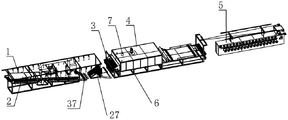
FIG. 1 is a schematic structural view of the present invention as a whole;
FIG. 2 is a schematic view of the drying oven according to the present invention;
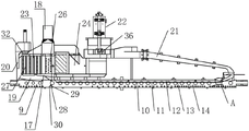
FIG. 3 is a schematic view of the internal structure of the drying oven according to the present invention;
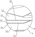
FIG. 4 is an enlarged view of portion A of FIG. 3;
FIG. 5 is a schematic view of the structure of the cooling device of the present invention;
FIG. 6 is a partial cross-sectional view of the air cooling mechanism of the present invention;
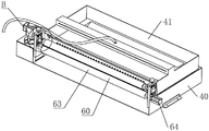
FIG. 7 is a schematic structural view of a water absorbing mechanism according to the present invention;
FIG. 8 is an enlarged view of the portion B of FIG. 7;
FIG. 9 is an enlarged view of the portion C of FIG. 8;
FIG. 10 is a partial cross-sectional view of the water absorbing mechanism of the present invention;
FIG. 11 is an enlarged view of portion D of FIG. 10 according to the present invention;
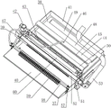
FIG. 12 is a schematic view of the structure of the drying apparatus according to the present invention;
fig. 13 is a schematic structural view of the drying device of the present invention with the drying box removed.
In the figure: 1. a paying-off wheel; 2. an annealing furnace; 3. a painting device; 4. a drying device; 5. a take-up device; 6. a drying rack; 7. a drying oven; 8. a furnace body; 9. a heating channel; 10. a first separator; 11. a second separator; 12. a first hot runner chamber; 13. a second heat flux chamber; 14. a flow homogenizing cavity; 15. a first overflow aperture; 16. a second overflowing hole; 17. a heating chamber; 18. an exhaust port; 19. a return channel; 20. a forward circulation channel; 21. a reverse circulation channel; 22. a circulating mechanism; 23. a preheating section; 24. a catalytic combustion section; 25. an electric heating device; 26. a heat exchanger; 28. an inverted V-shaped baffle; 29. a first flow guide part; 30. a second flow guide part; 31. a connecting bin; 32. a heat collecting pipe; 33. a first conduit; 34. a second conduit; 35. a reinforcing plate; 36. a circulating fan; 37. a cooling device; 38. a water cooling mechanism; 39. an air cooling mechanism; 40. a lower water tank; 41. a water feeding tank; 42. a water pump; 43. a wire passing hole; 44. a water return frame; 45. a water return port; 46. a water inlet interface; 47. a water pipe; 48. a water return table; 49. a water outlet; 50. a diversion bevel; 51. air cooling; 52. an air cooling box; 53. an air inlet pipe; 54. a conduit; 55. a limit nut; 56. a wind hole; 57. a guide wheel frame; 58. a first rotating shaft; 59. a wire guide wheel; 60. a water absorbing mechanism; 61. mounting a bracket; 62. a second rotating shaft; 63. a first water suction roller; 64. a first drive motor; 65. a first absorbent cotton sleeve; 66. installing a transverse plate; 67. a lead screw; 68. a hand wheel; 69. a clamp spring; 70. a lead screw nut; 71. a slider; 72. a guide convex strip; 73. a guide chute; 74. a second suction roll; 75. a second absorbent cotton sleeve; 76. a boss portion; 77. a support member; 78. a guide post; 79. positioning a plate; 80. a return spring; 81. a trace hole; 82. a locking portion; 83. a rotating part; 84. an unlocking portion; 85. positioning the circular groove; 86. a push rod; 87. positioning a nut; 88. a conical convex surface; 89. a conical concave surface; 90. a first annular groove; 91. a second annular groove; 92. a first clamping ring; 93. a second pressing ring; 94. a rolling channel; 95. a ball bearing; 96. a first annular limiting part; 97. a second annular limiting part; 98. a rolling gap; 99. drying the tripod; 100. a drying box; 101. a drying duct; 102. an air guide pipe; 103. a material guide pipe; 104. a vent hole; 105. a guide bar; 106. a pull wire assembly; 107. a second drive motor; 108. a belt transmission case; 109. and (4) a wire drawing roller.
Detailed Description
The technical solutions in the embodiments of the present invention will be clearly and completely described below with reference to the drawings in the embodiments of the present invention, and it is obvious that the described embodiments are only a part of the embodiments of the present invention, and not all of the embodiments. All other embodiments, which can be derived by a person skilled in the art from the embodiments given herein without making any creative effort, shall fall within the protection scope of the present invention.
Example (b): the horizontal enamelling machine shown in the attached figures 1-13 comprises an paying-off wheel 1, an annealing furnace 2, an enamelling device 3, a drying device 4 and a take-up device 5, wherein a cooling device can be arranged between the drying device 4 and the take-up device 5, the cooling device can be combined by air cooling and water cooling, copper wires paid off by the paying-off wheel 1 sequentially pass through the annealing furnace 2, the enamelling device 3 and the drying device 4 to carry out annealing, enamelling and drying processes, and finally take-up is carried out by the take-up device 5; the drying device 4 comprises a drying rack 6, a drying oven 7 is arranged on the drying rack 6, the drying oven 7 comprises an oven body 8, a heating channel 9 for passing the enameled wire is arranged below the oven body 8, the heating channel 9 is divided into a first heat flow cavity 12, a second heat flow cavity 13 and a uniform flow cavity 14 through a first partition plate 10 and a second partition plate 11, a plurality of first overflowing holes 15 used for communicating the first heat flow cavity 12 with the second heat flow cavity 13 are formed in the first partition plate 10, a plurality of second overflowing holes 16 used for communicating the second heat flow cavity 13 with the uniform flow cavity 14 are formed in the second partition plate 11, and the orthographic projection of the first overflowing holes 15 on the second partition plate 11 is not overlapped with the second overflowing holes 16; a heating chamber 17 is arranged in the furnace body 8 above the heating channel 9, an exhaust port 18 is arranged above the heating chamber 17, the flow equalizing cavity 14 of the heating channel 9 is communicated with the heating chamber 17 through a backflow channel 19, the heating chamber 17 is provided with a forward circulating channel 20 communicated with the head end of the flow equalizing cavity 14 of the heating channel 9 relative to the transmission direction of the enameled wire and a reverse circulating channel 21 communicated with the tail end of the first overflowing cavity of the heating channel 9 relative to the transmission direction of the enameled wire, the forward circulating channel 20 and the reverse circulating channel 21 are both in a C-shaped structure, the heating chamber 17, the forward circulating channel 20 and the heating channel 9 form a forward solvent circulation for evaporating the organic solvent carried by the enameled wire and sending the organic solvent into the heating chamber 17, and the reverse circulating channel 21, the heating channel 9 and the backflow channel 19 form a reverse heating circulation for baking the enameled wire by hot air flow, the heating chamber 17 is provided with a circulating mechanism 22 for driving airflow to continuously circulate along a forward solvent cycle and a reverse heating cycle, the heating chamber 17 is sequentially provided with a preheating part 23 for preheating the organic solvent and a catalytic combustion part 24 for catalytically combusting the preheated organic solvent, and the preheating part 23 comprises an electric heating device 25 and a heat exchanger 26 for exchanging heat with the catalytic combustion part 24.
After the enameled wire is painted, the surface of the enameled wire is often adhered with an organic solvent, the organic solvent is required to be filtered before waste gas is exhausted to the outside, the organic solvent is reasonably utilized to be catalytically heated, energy is saved while filtering cost is saved, and electric energy effect is reduced, when the enameled wire enters the furnace body 8 through the inlet of the heating channel 9, the organic solvent carried by the enameled wire is evaporated by airflow of forward solvent circulation and is sent into the heating chamber 17, the temperature required by catalysis is reached in the heating chamber 17, the formed heat is catalyzed by a catalyst (noble metal), the formed heat enters reverse heating circulation through hot airflow, the hot airflow of the enameled wire transmitted along the heating channel 9 is formed, the hot drying function is realized, then, the first preheating temperature of the organic solvent in the heating chamber 17 is realized by the electric heating device 25, and then the heat is realized through the heat exchanger 26 exchanging heat with the catalytic combustion part 24, the enameled wire passes through the uniform flow cavity 14, because the orthographic projection of the first overflowing hole 15 on the first partition plate 10 on the second partition plate 11 is not overlapped with the second overflowing hole 16, hot air flows enter the second hot flow cavity 13 through the first partition plate 10 and then is dispersed by the resistance of the second partition plate 11, so that the hot air flows are more uniform, and then the hot air flows pass through the second partition plate 11 to enter the uniform flow cavity 14 to heat and dry the enameled wire, so that the uniform heat can be kept, the condition that the enameled wire drying effect is poor due to large longitudinal temperature difference is avoided, and the quality of a finished enameled wire product is improved.
As shown in fig. 4, the plurality of first overflowing holes 15 are distributed on the first partition plate 10 in a manner that the intervals become larger gradually along the enamel wire conveying direction, and the plurality of second overflowing holes 16 are uniformly distributed on the second partition plate 11. First baffle 10 carries out first heat reposition of redundant personnel process for get into the heat current distribution in the second heat flow chamber 13 even, second baffle 11 further carries out the second and says the heat reposition of redundant personnel process, makes the heat current distribution that gets into in the homoflow chamber 14 more even, thereby promotes the stoving effect of enameled wire.
As shown in fig. 3, an inverted V-shaped baffle 28 is disposed at the bottom of the uniform flow cavity 14 of the heating channel 9, and the inverted V-shaped baffle 28 includes a first flow guiding portion 29 for guiding the hot air flow entering the uniform flow cavity 14 during the reverse heating cycle to the return channel 19 and a second flow guiding portion 30 for guiding the hot air flow entering the heating channel 9 during the forward heating cycle to the return channel 19. The design can effectively guide hot air flow in the heating channel 9 in the forward heating circulation and hot air flow in the heating channel 9 in the reverse heating circulation into the return channel 19, thereby realizing effective circulation of the hot air flow, improving the heat utilization rate of equipment and reducing energy consumption.
As shown in fig. 2 and fig. 3, a connecting bin 31 is respectively disposed at two sides of the heating chamber 17 on the furnace body 8, a plurality of heating pipes 32 are connected between the two connecting bins 31, the plurality of heating pipes 32 are disposed in the heating chamber 17, and a first pipeline 33 and a second pipeline 34 are respectively connected to the two connecting bins 31 at positions outside the furnace body 8. Because many devices of enamelling machine all need heat, add heat pipe 32 and can effectively utilize the heat in heating chamber 17, take away local heat through first pipeline 33 and second pipeline 34, regard local heat as the heat supply of other devices, simplify the heat supply structure of equipment, further improve energy-conserving effect.
As shown in fig. 3, a plurality of reinforcing plates 35 are distributed on the outer wall of the heating passage 9 and the outer wall of the reverse circulation passage 21 in the respective path directions. This design can promote the structural strength of heating passageway 9 and reverse circulation passageway 21, and the material takes place to warp when avoiding the temperature change.
As shown in fig. 3, the circulating mechanism 22 includes a circulating fan 36 fixed to the furnace body 8 (the circulating fan 36 is a mature product, and is relatively easily available on the market, and therefore, the detailed structure thereof is not described in detail herein), and the circulating fan 36 is located at the intersection of the forward circulating path 20 and the reverse circulating path 21 and forms a negative pressure that guides the air flow to the forward circulating path 20 and the reverse circulating path 21. The circulating fan 36 is arranged and adjusted to the intersection of the forward circulating channel 20 and the reverse circulating channel 21, and meanwhile, the airflow is guided to the forward circulating channel 20 and the reverse circulating channel 21, so that the structural simplicity is guaranteed.
As shown in fig. 1, 5 and 6, be equipped with the drying device who is used for copper line refrigerated cooling device 37 and is used for copper line dehumidification in proper order between annealing stove 2 and the painting device 3, cooling device 37 includes water-cooling mechanism 38 and air-cooled mechanism 39, water-cooling mechanism 38 includes lower water tank 40, upper water tank 41 and water pump 42, one side that upper water tank 41 is close to painting device 3 is equipped with a plurality of wire passing holes 43 that supply the copper line to pass, return water frame 44 is installed at the position that is close to painting device 3 on upper water tank 41, return water frame 44 has seted up return water mouth 45 near one side of painting device 3 along length direction, return water frame 44 top be equipped with the interface 46 of intaking that return water mouth 45 is linked together, the entrance point of water pump 42 sets up in lower water tank 40, the exit end of water pump 42 pass through water pipe 47 with interface 46 of intaking is linked together, upper water tank 41 bottom still is equipped with return water platform 48, a lower water port 49 communicated with the lower water tank 40 is formed in the part, close to the annealing furnace 2, of the water return table 48, the lower water port 49 is obliquely arranged from top to bottom towards the painting device 3, and a flow guide inclined surface 50 is arranged on one side, close to the painting device 3, of the water return table 48; the air cooling mechanism 39 comprises an air cooling frame 51 arranged on the lower water tank 40, an air cooling box 52 is arranged on the air cooling frame 51, one end of the air cooling box 52 is connected with an air inlet pipe 53, the air cooling box 52 is provided with a plurality of guide pipes 54 for guiding wires to pass through in a penetrating mode along the length direction, two ends of each guide pipe 54 are respectively in threaded connection with a limiting nut 55 used for abutting against two sides of the air cooling box 52, the side portion of each guide pipe 54 is provided with a plurality of air holes 56, the lower water tank 40 is further provided with a guide wheel frame 57, a first rotating shaft 58 is arranged on each guide wheel frame 57, and a guide wheel 59 is rotatably arranged on each first rotating shaft 58. This design can effectively cool down, wash and dry the copper line after the annealing to guarantee the quality of follow-up copper line japanning.
As shown in fig. 7 and 10, the water absorbing device 60 is further included, the water absorbing device 60 is disposed on the lower water tank 40 and is close to the thread passing hole 43 of the upper water tank 41, the water absorbing device 60 includes two mounting brackets 61 symmetrically disposed on both sides of the lower water tank 40, a first water absorbing roller 63 is rotatably connected between the two mounting brackets 61 through a second rotating shaft 62, a first driving motor 64 is mounted on one of the mounting brackets 61, a motor shaft of the first driving motor 64 is linked with one end of the second rotating shaft 62, a first water absorbing cotton sleeve 65 is wrapped on a side portion of the first water absorbing roller 63, a mounting transverse plate 66 is disposed on a top portion of the mounting bracket 61, a lead screw 67 is disposed on the mounting transverse plate 66 in a penetrating manner, a hand wheel 68 is disposed on a top end of the lead screw 67, two snap springs 69 respectively abutting against upper and lower sides of the mounting transverse plate 66 are clamped on the lead screw 67, a lead screw nut 70 matched with a bottom end of the lead screw 67 is further disposed on the mounting bracket 61, the lead screw 67 is connected with a sliding block 71 in a threaded manner, two sides of the sliding block 71 are respectively provided with a guide protruding strip 72, the mounting brackets 61 are provided with guide sliding grooves 73 matched with the guide protruding strips 72, a second water suction roller 74 which is in extrusion fit with the first water suction roller 63 is connected between the sliding blocks 71 on the two mounting brackets 61, the side part of the second water suction roller 74 is coated with a second water suction cotton sleeve 75, and a copper wire passes through the first water suction cotton sleeve 65 and the second water suction cotton sleeve 75 to perform a dehumidification process. This design can carry out the surface to the copper line after the water-cooling is handled and absorb water, and step-by-step its drying of accelerating can avoid copper line surface to have water stain moreover and influence the japanning quality.
As shown in fig. 7 to 11, a sleeve portion 76 is provided in the slider 71, a support member 77 is connected to the sleeve portion 76, the support member 77 includes a guide post 78 and a positioning plate 79 integrally provided, the guide post 78 is inserted into the corresponding sleeve portion 76, a return spring 80 acting on the guide post 78 is provided in the sleeve portion 76, a track hole 81 is provided in a side portion of the sleeve portion 76, the track hole 81 includes a locking portion 82 extending in an axial direction, a rotating portion 83 extending in a circumferential direction, and an unlocking portion 84 extending in the axial direction, which are sequentially connected, a positioning circular groove 85 is provided in a portion of an outer side of the sleeve portion 76, which is located at one end of the locking portion 82 away from the rotating portion 83, a push rod 86 is threadedly connected to a side portion of the guide post 78, the push rod 86 penetrates through the track groove, a positioning nut 87 is threadedly connected to the push rod 86, and when the positioning nut 87 moves downward on the push rod 86, the positioning nut 87 is embedded in the positioning circular groove 85; the two ends of the second water suction roller 74 are provided with conical convex surfaces 88, one end surface of the positioning disc 79, which is close to the second water suction roller 74, is provided with a conical concave surface 89 matched with the conical convex surface 88, the conical concave surface 89 is concentrically provided with a first annular groove 90 and a second annular groove 91, the first annular groove 90 and the second annular groove 91 are respectively provided with a first pressing ring 92 and a second pressing ring 93 in interference fit, a rolling channel 94 is arranged between the first pressing ring 92 and the second pressing ring 93, a plurality of balls 95 are arranged in the rolling channel 94 in a rolling manner, the outer end of the first pressing ring 92 is provided with a first annular limiting part 96 which extends inwards and is used for limiting the balls 95, the outer end of the second pressing ring 93 is provided with a second annular limiting part 97 which extends outwards and is used for limiting the balls 95, and a rolling gap 98 for extending the balls 95 is arranged between the first annular limiting part 96 and the second annular limiting part 97, the outer ends of the balls 95 extend out of the rolling gap 98 and abut against the corresponding conical lands 88 on the second suction roll 74. This design greatly facilitates the disassembly and assembly of the second suction roll 74, facilitating the later replacement of the second suction cotton sleeve 75.
As shown in fig. 12 and 13, the drying device includes a drying tripod 99, a drying box 100 is disposed on an inclined surface of the drying tripod 99, a drying pipe 101 is disposed in the drying box 100, an air guide pipe 102 for connecting with an air source is disposed on the drying pipe 101, a plurality of material guide pipes 103 for copper wires to pass through are disposed on the drying box 100 in a penetrating manner, the material guide pipes 103 pass through the air guide pipe 102, and a vent hole 104 is disposed on a side portion of the material guide pipes 103 located inside the air guide pipe 102; the drying tripod 99 is provided with a guide rod 105 for guiding a copper wire at a position close to the lower end of the material guide pipe 103, a wire pulling assembly 106 for transmitting the copper wire is arranged at a position close to the upper end of the material guide pipe 103 of the drying tripod 99, the wire pulling assembly 106 comprises a second driving motor 107, two belt transmission boxes 108 and a wire pulling roller 109, the two belt transmission boxes 108 are symmetrically arranged on the drying tripod 99, a motor shaft of the second driving motor 107 is connected with an input shaft of one of the belt transmission boxes 108, and two ends of the wire pulling roller 109 are respectively connected with output ends of the two belt transmission boxes 108. This design can further carry out drying process to the copper line, thoroughly gets rid of the moisture on copper line surface to insulating varnish can firmly effectively adhere to on the copper line when guaranteeing the later stage japanning.
Claims (10)
1. The horizontal enamelling machine comprises an paying-off wheel (1), an annealing furnace (2), an enamelling device (3), a drying device (4) and a wire-collecting device (5), wherein copper wires paid off by the paying-off wheel (1) sequentially pass through the annealing furnace (2), the enamelling device (3) and the drying device (4) to carry out annealing, enamelling and drying processes, and are finally collected by the wire-collecting device (5); the method is characterized in that: the drying device (4) comprises a drying rack (6), a drying furnace (7) is arranged on the drying rack (6), the drying furnace (7) comprises a furnace body (8), a heating channel (9) for the enameled wire to pass through is arranged below the furnace body (8), the heating channel (9) is divided into a first heat flow cavity (12), a second heat flow cavity (13) and a uniform flow cavity (14) through a first partition plate (10) and a second partition plate (11), a plurality of first overflowing holes (15) used for communicating the first heat flow cavity (12) with the second heat flow cavity (13) are formed in the first partition plate (10), a plurality of second overflowing holes (16) used for communicating the second heat flow cavity (13) with the uniform flow cavity (14) are formed in the second partition plate (11), and the orthographic projection of the first overflowing hole (15) on the second partition plate (11) is not overlapped with the second overflowing hole (16); a heating chamber (17) is arranged at a position above the heating channel (9) in the furnace body (8), an exhaust port (18) is arranged above the heating chamber (17), a uniform flow cavity (14) of the heating channel (9) is communicated with the heating chamber (17) through a backflow channel (19), the heating chamber (17) is provided with a forward circulating channel (20) communicated with the head end of the uniform flow cavity (14) of the heating channel (9) relative to the transmission direction of the enameled wire and a reverse circulating channel (21) communicated with the tail end of a first overflowing cavity of the heating channel (9) relative to the transmission direction of the enameled wire, the heating chamber (17), the forward circulating channel (20) and the heating channel (9) form a forward solvent circulation for evaporating an organic solvent carried by the enameled wire and sending the organic solvent into the heating chamber (17), and the heating chamber (17), the reverse circulating channel (21), the heating channel (9) and the backflow channel (19) form a reverse heating circulation for heating the enameled wire by means of hot baking, the heating chamber (17) is provided with a circulating mechanism (22) for driving airflow to continuously circulate along a forward solvent cycle and a reverse heating cycle, the heating chamber (17) is sequentially provided with a preheating part (23) for preheating the organic solvent and a catalytic combustion part (24) for catalytically combusting the preheated organic solvent, and the preheating part (23) comprises an electric heating device (25) and a heat exchanger (26) for exchanging heat with the catalytic combustion part (24).
2. The horizontal enameling machine according to claim 1, characterized in that: the first overflowing holes (15) are distributed on the first partition plate (10) in a mode that intervals gradually increase along the transmission direction of the enameled wire, and the second overflowing holes (16) are uniformly distributed on the second partition plate (11).
3. The horizontal enameling machine according to claim 1, characterized in that: the bottom of the uniform flow cavity (14) of the heating channel (9) is provided with an inverted V-shaped guide plate (28), and the inverted V-shaped guide plate (28) comprises a first guide part (29) for guiding hot air flow entering the uniform flow cavity (14) to the backflow channel (19) in the reverse heating circulation process and a second guide part (30) for guiding hot air flow entering the heating channel (9) to the backflow channel (19) in the forward heating circulation process.
4. The horizontal enameling machine according to claim 1, characterized in that: the heating furnace is characterized in that the furnace body (8) is provided with a connecting bin (31) at two sides of the heating chamber (17), a plurality of heat collecting pipes (32) are connected between the two connecting bins (31), the plurality of heat collecting pipes (32) are arranged in the heating chamber (17), and the two connecting bins (31) are connected with a first pipeline (33) and a second pipeline (34) at positions outside the furnace body (8).
5. The horizontal enameling machine according to claim 1, characterized in that: a plurality of reinforcing plates (35) are uniformly distributed on the outer wall of the heating channel (9) and the outer wall of the reverse circulation channel (21) along the respective path directions.
6. The horizontal enameling machine according to claim 1, characterized in that: the circulating mechanism (22) comprises a circulating fan (36) fixed on the furnace body (8), wherein the circulating fan (36) is positioned at the intersection of the forward circulating channel (20) and the reverse circulating channel (21) and forms negative pressure for guiding airflow to the forward circulating channel (20) and the reverse circulating channel (21).
7. The horizontal enameling machine according to claim 1, characterized in that: annealing stove (2) and painting device (3) are equipped with in proper order between and are used for copper line refrigerated cooling device (37) and be used for the drying device of copper line dehumidification, cooling device (37) include water-cooling mechanism (38) and forced air cooling mechanism (39), water-cooling mechanism (38) include lower water tank (40), upper water tank (41) and water pump (42), one side that upper water tank (41) are close to painting device (3) is equipped with a plurality of wire passing holes (43) that supply the copper line to pass, upper water tank (41) are gone up the position that is close to painting device (3) and are installed return water frame (44), return water mouth (45) have been seted up along length direction to one side that return water frame (44) are close to painting device (3), return water frame (44) top be equipped with inlet interface (46) that return water mouth (45) are linked together, the entrance point of water pump (42) sets up in lower water tank (40), the outlet end of the water pump (42) is communicated with the water inlet connector (46) through a water pipe (47), the bottom in the upper water tank (41) is also provided with a water return table (48), the part, close to the annealing furnace (2), of the water return table (48) is provided with a lower water gap (49) communicated with the lower water tank (40), the lower water gap (49) is obliquely arranged from top to bottom towards the painting device (3), and one side, close to the painting device (3), of the water return table (48) is provided with a flow guide inclined plane (50); air-cooled mechanism (39) is including setting up air-cooled frame (51) on lower water tank (40), install air-cooled case (52) on air-cooled frame (51), the one end of air-cooled case (52) is connected with air-supply line (53), air-cooled case (52) are provided with a plurality of pipes (54) that are used for the wire to pass along length direction run through, one stop nut (55) that are used for supporting in air-cooled case (52) both sides is connected to pipe (54) both ends difference threaded connection, a plurality of wind holes (56) have been seted up to pipe (54) lateral part, still be equipped with down on water tank (40) and lead wheel frame (57), install first pivot (58) on lead wheel frame (57), rotate on first pivot (58) and install wire wheel (59).
8. The horizontal enameling machine according to claim 7, characterized in that: the water absorption device is characterized by further comprising a water absorption mechanism (60) which is arranged on the lower water tank (40) and close to the wire passing hole (43) of the upper water tank (41), wherein the water absorption mechanism (60) comprises two mounting brackets (61) which are symmetrically arranged on two sides of the lower water tank (40), a first water absorption roller (63) is rotatably connected between the two mounting brackets (61) through a second rotating shaft (62), a first driving motor (64) is mounted on one mounting bracket (61), a motor shaft of the first driving motor (64) is in linkage connection with one end of the second rotating shaft (62), a first water absorption cotton sleeve (65) is wrapped on the side part of the first water absorption roller (63), an installation transverse plate (66) is arranged on the top of the mounting bracket (61), a lead screw (67) is arranged on the installation transverse plate (66) in a penetrating manner, a hand wheel (68) is arranged at the top end of the lead screw (67), two clamp springs (69) which respectively abut against the upper side and the lower side of the installation transverse plate (66) are clamped on the lead screw (67), still be equipped with on installing support (61) with lead screw (67) bottom matched with screw nut (70), threaded connection has slider (71) on lead screw (67), the both sides of slider (71) are equipped with one direction sand grip (72) respectively, be equipped with on installing support (61) with direction sand grip (72) matched with direction spout (73), be connected with between slider (71) on two installing support (61) and be used for constituting extrusion fit's second with first roller (63) that absorbs water and absorb water roller (74), the lateral part cladding of second roller (74) that absorbs water has the cotton cover of second (75) that absorbs water, and the copper line passes first cotton cover of absorbing water (65) and the cotton cover of second (75) that absorbs water and dehumidifies the process.
9. The horizontal enameling machine according to claim 8, characterized in that: a shaft sleeve part (76) is arranged in the sliding block (71), a supporting part (77) is connected to the shaft sleeve part (76), the supporting part (77) comprises a guide post (78) and a positioning disc (79) which are integrally arranged, the guide post (78) is inserted in the corresponding shaft sleeve part (76), a return spring (80) acting on the guide post (78) is arranged in the shaft sleeve part (76), a track hole (81) is formed in the side part of the shaft sleeve part (76), the track hole (81) comprises a locking part (82) which extends along the axial direction, a rotating part (83) which extends along the circumferential direction and an unlocking part (84) which extends along the axial direction which are sequentially connected, a positioning circular groove (85) is formed in a part, which is located at one end of the locking part (82) far away from the rotating part (83), in the outer side part of the shaft sleeve part (76), a push rod (86) is in threaded connection with the guide post (78), and the push rod (86) penetrates through the track groove, the push rod (86) is in threaded connection with a positioning nut (87), and after the positioning nut (87) moves downwards on the push rod (86), the positioning nut (87) is embedded in the positioning circular groove (85); the two ends of the second water suction roller (74) are provided with conical convex surfaces (88), one end face, close to the second water suction roller (74), of the positioning disc (79) is provided with a conical concave surface (89) matched with the conical convex surfaces (88), the conical concave surface (89) is provided with a first annular groove (90) and a second annular groove (91) in a concentric ring mode, the first annular groove (90) and the second annular groove (91) are respectively provided with a first pressing ring (92) and a second pressing ring (93) in an interference fit mode, a rolling channel (94) is arranged between the first pressing ring (92) and the second pressing ring (93), the rolling channel (94) is internally provided with a plurality of balls (95) in a rolling mode, the outer end of the first pressing ring (92) is provided with a first annular limiting portion (96) which extends inwards and is used for limiting the outer ends (95), the second pressing ring (93) is provided with a second annular limiting portion (97) which extends outwards and is used for limiting the balls (95), and a rolling gap (98) for extending the outer end of the ball (95) is arranged between the first annular limiting part (96) and the second annular limiting part (97), and the outer end of the ball (95) extends out of the rolling gap (98) and abuts against the corresponding conical convex surface (88) on the second water suction roller (74).
10. The horizontal enameling machine according to claim 7, characterized in that: the drying device comprises a drying tripod (99), a drying box (100) is arranged on the inclined surface of the drying tripod (99), a drying pipe (101) is arranged in the drying box (100), an air guide pipe (102) used for being connected with an air source is arranged on the drying pipe (101), a plurality of material guide pipes (103) for copper wires to pass through are arranged on the drying box (100) in a penetrating manner, the material guide pipes (103) penetrate through the air guide pipe (102), and ventilation holes (104) are formed in the side parts, located in the air guide pipe (102), of the material guide pipes (103); the utility model discloses a drying device, including drying tripod (99), guide tube (103), stay wire assembly (106), second driving motor (107), two belt transmission case (108) and stay wire roller (109), drying tripod (99) are equipped with guide arm (105) that are used for guiding the copper line near the position of passage (103) lower extreme, drying tripod (99) are equipped with stay wire assembly (106) that are used for transmitting the copper line near the position of passage (103) upper end, stay wire assembly (106) include second driving motor (107), two belt transmission case (108) and stay wire roller (109), and two belt transmission case (108) symmetry are installed on drying tripod (99), the motor shaft of second driving motor (107) is connected with the input shaft of one of them belt transmission case (108), the both ends of stay wire roller (109) are connected with the output of two belt transmission case (108) respectively.
Applications Claiming Priority (2)
| Application Number | Priority Date | Filing Date | Title |
|---|---|---|---|
| CN2022101409871 | 2022-02-16 | ||
| CN202210140987 | 2022-02-16 |
Publications (2)
| Publication Number | Publication Date |
|---|---|
| CN114512285A true CN114512285A (en) | 2022-05-17 |
| CN114512285B CN114512285B (en) | 2024-01-30 |
Family
ID=81554572
Family Applications (1)
| Application Number | Title | Priority Date | Filing Date |
|---|---|---|---|
| CN202210170732.XA Active CN114512285B (en) | 2022-02-16 | 2022-02-24 | Horizontal enamelling machine |
Country Status (1)
| Country | Link |
|---|---|
| CN (1) | CN114512285B (en) |
Cited By (1)
| Publication number | Priority date | Publication date | Assignee | Title |
|---|---|---|---|---|
| CN117316549A (en) * | 2023-10-16 | 2023-12-29 | 无锡市瑞球科技有限公司 | Vertical enameled wire wind circulating device |
Citations (8)
| Publication number | Priority date | Publication date | Assignee | Title |
|---|---|---|---|---|
| CN2641554Y (en) * | 2003-06-03 | 2004-09-15 | 苏尚远 | Double circulation type horizontal enameling machine dryoff oven |
| CN2796037Y (en) * | 2005-04-08 | 2006-07-12 | 江门市新会区新健机电设备材料有限公司 | Novel horizontal catalytic burning heat exchanging and hot air circulation lacquered wire machine baking stove |
| CN102368412A (en) * | 2011-09-14 | 2012-03-07 | 吴江市神州机械有限公司 | Cyclic baking method of enamelled wire and oven for realizing method |
| CN204332547U (en) * | 2014-12-30 | 2015-05-13 | 成都西南电工有限公司 | The enamelled wire curing range that a kind of Temperature Distribution is controlled |
| CN205264426U (en) * | 2015-12-31 | 2016-05-25 | 无锡巨一同创科技有限公司 | Energy -conserving baker |
| CN106205860A (en) * | 2016-06-27 | 2016-12-07 | 佛山市顺德区盛永机械有限公司 | A kind of multipurpose horizontal aluminum steel enamelling machine |
| CN209388781U (en) * | 2018-10-11 | 2019-09-13 | 金颖 | A kind of horizontal enameling machine |
| CN215815398U (en) * | 2021-01-29 | 2022-02-11 | 浙江华亿电气有限公司 | Energy-saving drying furnace of horizontal enamelling machine |
-
2022
- 2022-02-24 CN CN202210170732.XA patent/CN114512285B/en active Active
Patent Citations (8)
| Publication number | Priority date | Publication date | Assignee | Title |
|---|---|---|---|---|
| CN2641554Y (en) * | 2003-06-03 | 2004-09-15 | 苏尚远 | Double circulation type horizontal enameling machine dryoff oven |
| CN2796037Y (en) * | 2005-04-08 | 2006-07-12 | 江门市新会区新健机电设备材料有限公司 | Novel horizontal catalytic burning heat exchanging and hot air circulation lacquered wire machine baking stove |
| CN102368412A (en) * | 2011-09-14 | 2012-03-07 | 吴江市神州机械有限公司 | Cyclic baking method of enamelled wire and oven for realizing method |
| CN204332547U (en) * | 2014-12-30 | 2015-05-13 | 成都西南电工有限公司 | The enamelled wire curing range that a kind of Temperature Distribution is controlled |
| CN205264426U (en) * | 2015-12-31 | 2016-05-25 | 无锡巨一同创科技有限公司 | Energy -conserving baker |
| CN106205860A (en) * | 2016-06-27 | 2016-12-07 | 佛山市顺德区盛永机械有限公司 | A kind of multipurpose horizontal aluminum steel enamelling machine |
| CN209388781U (en) * | 2018-10-11 | 2019-09-13 | 金颖 | A kind of horizontal enameling machine |
| CN215815398U (en) * | 2021-01-29 | 2022-02-11 | 浙江华亿电气有限公司 | Energy-saving drying furnace of horizontal enamelling machine |
Cited By (2)
| Publication number | Priority date | Publication date | Assignee | Title |
|---|---|---|---|---|
| CN117316549A (en) * | 2023-10-16 | 2023-12-29 | 无锡市瑞球科技有限公司 | Vertical enameled wire wind circulating device |
| CN117316549B (en) * | 2023-10-16 | 2024-03-26 | 无锡市瑞球科技有限公司 | Vertical enameled wire wind circulating device |
Also Published As
| Publication number | Publication date |
|---|---|
| CN114512285B (en) | 2024-01-30 |
Similar Documents
| Publication | Publication Date | Title |
|---|---|---|
| CN104549845B (en) | Without edges of boards LED display paint spraying apparatus | |
| CN115295249B (en) | Cable painting production method | |
| CN114512285B (en) | Horizontal enamelling machine | |
| CN103956218B (en) | Device and technology for producing enameled round aluminum wires | |
| CN115249555B (en) | Automatically controlled enameling machine for enameled wire film | |
| CN110172660B (en) | Tin-plated welding strip cooling system and cooling method thereof | |
| CN211538366U (en) | Coating equipment | |
| CN209388781U (en) | A kind of horizontal enameling machine | |
| CN116083830A (en) | Steel structure surface galvanization equipment for steel structure processing | |
| CN120756108A (en) | A laminating device | |
| CN210481497U (en) | Tin-plating solder strip cooling system | |
| CN115831475B (en) | Continuously running unattended small and medium-sized multi-head enameling machines | |
| CN117116568B (en) | Processing equipment and process for parallel multi-core composite enameled wire | |
| CN203209268U (en) | Shake-proof and rust-proof surface coating equipment of elevator compensation chain | |
| CN218100817U (en) | Special winding mechanism for fine enameled wire | |
| CN215209591U (en) | Anti-oxidant tinning stack of tinned copper wire environmental protection | |
| CN215815398U (en) | Energy-saving drying furnace of horizontal enamelling machine | |
| CN221099168U (en) | Drying mechanism of tinning production line | |
| CN210675793U (en) | Stainless steel wire film covering device | |
| CN216793395U (en) | Baking oven of enameling machine | |
| CN222106336U (en) | A heating device for electric wire production | |
| CN223988651U (en) | Spraying equipment is used in processing of aluminium veneer | |
| CN224167928U (en) | Pole piece coating and drying production line | |
| CN222132523U (en) | Cooling device for color coating production line | |
| CN223276615U (en) | Welding strip scaling powder drying device and welding strip scaling powder coating system |
Legal Events
| Date | Code | Title | Description |
|---|---|---|---|
| PB01 | Publication | ||
| PB01 | Publication | ||
| SE01 | Entry into force of request for substantive examination | ||
| SE01 | Entry into force of request for substantive examination | ||
| GR01 | Patent grant | ||
| GR01 | Patent grant | ||
| PE01 | Entry into force of the registration of the contract for pledge of patent right |
Denomination of invention: Horizontal lacquering machine Granted publication date: 20240130 Pledgee: Industrial and Commercial Bank of China Limited Lishui Economic Development Zone sub branch Pledgor: ZHEJIANG HUAYI ELECTRIC Co.,Ltd. Registration number: Y2024980037915 |
|
| PE01 | Entry into force of the registration of the contract for pledge of patent right |