CN114508079A - Multi-functional river sluice in ecological river course in city - Google Patents
Multi-functional river sluice in ecological river course in city Download PDFInfo
- Publication number
- CN114508079A CN114508079A CN202210082678.3A CN202210082678A CN114508079A CN 114508079 A CN114508079 A CN 114508079A CN 202210082678 A CN202210082678 A CN 202210082678A CN 114508079 A CN114508079 A CN 114508079A
- Authority
- CN
- China
- Prior art keywords
- river
- side wall
- bevel gear
- lead screw
- reciprocal lead
- Prior art date
- Legal status (The legal status is an assumption and is not a legal conclusion. Google has not performed a legal analysis and makes no representation as to the accuracy of the status listed.)
- Granted
Links
- 238000004062 sedimentation Methods 0.000 claims description 21
- 238000009434 installation Methods 0.000 claims description 19
- 230000005484 gravity Effects 0.000 claims description 8
- 230000005540 biological transmission Effects 0.000 claims description 5
- 230000008878 coupling Effects 0.000 claims description 4
- 238000010168 coupling process Methods 0.000 claims description 4
- 238000005859 coupling reaction Methods 0.000 claims description 4
- 210000001503 joint Anatomy 0.000 claims description 4
- 230000000149 penetrating effect Effects 0.000 claims description 4
- 238000007789 sealing Methods 0.000 claims description 2
- 238000004804 winding Methods 0.000 claims description 2
- 239000004576 sand Substances 0.000 claims 3
- 230000000694 effects Effects 0.000 abstract description 2
- XLYOFNOQVPJJNP-UHFFFAOYSA-N water Substances O XLYOFNOQVPJJNP-UHFFFAOYSA-N 0.000 description 12
- 238000003756 stirring Methods 0.000 description 8
- 230000000903 blocking effect Effects 0.000 description 3
- 238000000151 deposition Methods 0.000 description 3
- 238000010586 diagram Methods 0.000 description 3
- 230000002349 favourable effect Effects 0.000 description 3
- 230000002093 peripheral effect Effects 0.000 description 2
- 238000000926 separation method Methods 0.000 description 2
- 238000011144 upstream manufacturing Methods 0.000 description 2
- 230000009286 beneficial effect Effects 0.000 description 1
- 239000002352 surface water Substances 0.000 description 1
Images


Classifications
-
- E—FIXED CONSTRUCTIONS
- E02—HYDRAULIC ENGINEERING; FOUNDATIONS; SOIL SHIFTING
- E02B—HYDRAULIC ENGINEERING
- E02B7/00—Barrages or weirs; Layout, construction, methods of, or devices for, making same
- E02B7/20—Movable barrages; Lock or dry-dock gates
- E02B7/26—Vertical-lift gates
- E02B7/28—Vertical-lift gates with sliding gates
-
- E—FIXED CONSTRUCTIONS
- E02—HYDRAULIC ENGINEERING; FOUNDATIONS; SOIL SHIFTING
- E02B—HYDRAULIC ENGINEERING
- E02B7/00—Barrages or weirs; Layout, construction, methods of, or devices for, making same
- E02B7/20—Movable barrages; Lock or dry-dock gates
- E02B7/26—Vertical-lift gates
- E02B7/36—Elevating mechanisms for vertical-lift gates
-
- E—FIXED CONSTRUCTIONS
- E02—HYDRAULIC ENGINEERING; FOUNDATIONS; SOIL SHIFTING
- E02B—HYDRAULIC ENGINEERING
- E02B8/00—Details of barrages or weirs ; Energy dissipating devices carried by lock or dry-dock gates
-
- F—MECHANICAL ENGINEERING; LIGHTING; HEATING; WEAPONS; BLASTING
- F03—MACHINES OR ENGINES FOR LIQUIDS; WIND, SPRING, OR WEIGHT MOTORS; PRODUCING MECHANICAL POWER OR A REACTIVE PROPULSIVE THRUST, NOT OTHERWISE PROVIDED FOR
- F03B—MACHINES OR ENGINES FOR LIQUIDS
- F03B13/00—Adaptations of machines or engines for special use; Combinations of machines or engines with driving or driven apparatus; Power stations or aggregates
Landscapes
- Engineering & Computer Science (AREA)
- General Engineering & Computer Science (AREA)
- Structural Engineering (AREA)
- Mechanical Engineering (AREA)
- Civil Engineering (AREA)
- Chemical & Material Sciences (AREA)
- Combustion & Propulsion (AREA)
- Barrages (AREA)
- Transmission Devices (AREA)
Abstract
The application discloses multi-functional river floodgate of ecological river course in city belongs to the technical field that the city river course was administered, its including set up in the side wall of river course both sides, set up base on the bottom in the river course, set up in support frame on the base and install in gate on the support frame, the grit chamber has been seted up on the base, the vertical settling pipe that wears to be equipped with on the side wall, the settling pipe pass through connect passage with the grit chamber is linked together, the intercommunication has the discharge pipe on the tip that the settling pipe extends the side wall, be provided with the transportation subassembly that is used for transporting silt in the grit chamber, it is provided with the lifting plate to slide on the inside wall of settling pipe, be provided with on the settling pipe and be used for the drive the lifting unit that the lifting plate removed. This application has the effect that prevents silt deposit in the river course in sluice department.
Description
Technical Field
The application relates to the technical field of urban river treatment, in particular to a multifunctional river gate for an urban ecological river.
Background
The water conservancy project is a project constructed for controlling and allocating surface water and underground water in the nature so as to achieve the purposes of removing harms and benefiting purposes.
In the related art, the chinese patent application with publication number CN105756021A discloses a gate, which comprises a gate body and a gate frame, wherein the gate body is installed in the gate frame, and is connected with an opening and closing device for controlling the opening and closing of the gate body; an overflow pipe communicated with two sides of the gate is arranged in the gate body; and a valve for opening and closing the overflow pipe is arranged on an opening at one side of the overflow pipe.
In view of the above-mentioned related art, the inventor believes that when the gate is opened, silt at the upstream of the river channel is easy to move along with the river water, so that the silt is accumulated at the gate, on one hand, the gate is easy to be closed loosely, and on the other hand, silt sedimentation easily affects the water delivery function of the river channel.
Disclosure of Invention
In order to prevent silt deposit in the river course in sluice department, this application provides a multi-functional river sluice in ecological river course in city.
The application provides a multi-functional river floodgate in ecological river course in city adopts following technical scheme:
the utility model provides a multi-functional river floodgate in city ecological river course, including set up in the side wall of river course both sides, set up base on the bottom in the river course, set up in support frame on the base and install in gate on the support frame, the grit chamber has been seted up on the base, the vertical sedimentation pipe that wears to be equipped with on the side wall, the sedimentation pipe pass through the interface channel with the grit chamber is linked together, the intercommunication has the discharge pipe on the tip that the sedimentation pipe extends the side wall, be provided with the transportation subassembly that is used for transporting silt in the grit chamber, it is provided with the lifting plate to slide on the inside wall of sedimentation pipe, be provided with on the sedimentation pipe and be used for the drive the lifting unit that the lifting plate removed.
Through adopting above-mentioned technical scheme, when the gate is in the open mode, the silt of upper reaches enters into the grit chamber along with the rivers in, operating personnel makes the silt in the grit chamber get into the interface channel through the transportation subassembly in, in the silt in the interface channel finally gets into the settling tube, operating personnel utilizes lift assembly drive lifting plate to remove along the direction of height of settling tube, and then makes the silt that gets into in the settling tube pass through the discharge pipe and discharges, is favorable to preventing that the silt in the river course from depositing in sluice department.
Preferably, lifting unit includes vertical the reciprocal lead screw of vertical wearing to locate in the boundary wall, fixed cover are located worm wheel on the reciprocal lead screw and wear to locate worm in the boundary wall, first reciprocal lead screw passes the lifting plate and with lifting plate screw-thread fit, the worm with worm wheel intermeshing, be provided with on the boundary wall and be used for the drive worm pivoted power component.
Through adopting above-mentioned technical scheme, operating personnel makes the worm rotate through power component, and the worm rotates and makes the worm wheel rotate, and the worm wheel rotates and makes first reciprocal lead screw rotate, and then makes the lifting plate along first length direction reciprocating motion toward the multifilament pole.
Preferably, the power assembly comprises a positioning rod arranged on the side wall in a penetrating mode, a screw arranged on the positioning rod in a fixing sleeve mode, a first belt wheel is arranged on the positioning rod in a fixing sleeve mode, a second belt wheel is arranged on the worm in a fixing sleeve mode, and a first belt is arranged between the first belt wheel and the second belt wheel in a winding mode.
Through adopting above-mentioned technical scheme, when operating personnel opened the gate, water impact's screw rotated, and the screw rotates and makes the locating lever rotate, and the locating lever rotates and makes first band pulley rotate, and first band pulley makes the second band pulley rotate through first belt, and the second band pulley drives the worm and rotates, finally makes first reciprocal lead screw rotate, and the setting of locating lever and screw utilizes the water conservancy as power, is favorable to the energy saving.
Preferably, be provided with in the settling tube and be used for sealing the subassembly that blocks of interface channel, block the subassembly including sliding to wear to locate baffle in the settling tube, wear to locate the reciprocal lead screw of second in the side wall, the reciprocal lead screw of second penetrates in the baffle and with baffle screw-thread fit, be provided with in the side wall and be used for driving the rotatory runner assembly of the reciprocal lead screw of second.
Through adopting above-mentioned technical scheme, operating personnel utilizes rotating assembly to make the reciprocal lead screw of second rotate, and the reciprocal lead screw of second rotates and makes baffle reciprocating motion, and when the baffle removed completely to the settling tube in, the baffle will the connecting channel shutoff, and then prevents that silt in the connecting channel from getting into the lifting plate below, and when the baffle removed out the settling tube, silt in the connecting channel flowed into the lifting plate top.
Preferably, set up the installation cavity in the side wall, the runner assembly including rotate install in dwang on the top surface in the installation cavity, set up in first bevel gear, fixed cover on the dwang are located the reciprocal lead screw of second extends to second bevel gear on the installation cavity tip, first bevel gear with second bevel gear intermeshing, be provided with in the installation cavity and be used for the drive the rotatory coupling assembling of dwang.
Through adopting above-mentioned technical scheme, operating personnel makes the dwang rotate through coupling assembling, and the dwang rotates and makes first bevel gear rotate, and first bevel gear rotates and makes second bevel gear rotate, and second bevel gear rotates and makes the reciprocal lead screw of second rotate, final drive baffle reciprocating motion.
Preferably, coupling assembling including rotate install in the reciprocal lead screw of third of top surface in the installation cavity, fixed cover are located first rotating gear on the reciprocal lead screw of third, rotate install in second rotating gear and fixed cover on the top surface are located in the installation cavity third rotating gear on the dwang, second rotating gear set up in first rotating gear with between the second rotating gear, and second rotating gear respectively with first rotating gear, third rotating gear intermeshing, fixed cover is equipped with driving pulley on the reciprocal lead screw of first, fixed cover is equipped with driven pulley on the reciprocal lead screw of third, driving pulley with around being equipped with the drive belt between the driven pulley.
Through adopting above-mentioned technical scheme, when first reciprocal lead screw rotates, first reciprocal lead screw rotates and drives the driving pulley and rotate, the driving pulley passes through the drive belt and makes driven pulley rotate, driven pulley rotates and makes the reciprocal lead screw of third rotate, the reciprocal lead screw of third rotates and makes first rotating gear rotatory, first rotating gear is rotatory to make second rotating gear and third rotating gear rotatory, the third rotating gear is rotatory to make the dwang rotate, operating personnel rotates and the dwang rotates as the first reciprocal lead screw of power drive through rivers, and then the energy can be saved.
Preferably, the cover that slides on the dwang is equipped with the swivel becket, fixedly connected with stopper on the inside wall of swivel becket, seted up on the dwang be used for with the stopper complex spacing groove that slides, the swivel becket with first bevel gear fixed connection, the cover is equipped with the holding ring on the swivel becket, the holding ring with the swivel becket rotates to be connected, fixedly connected with gravity ring on the holding ring, just fixedly connected with fixed plate on the holding ring, the cover is equipped with on the reciprocal lead screw of third be used for with the reciprocal lead screw thread fit's butt plate of third, the butt plate with the fixed plate butt.
By adopting the technical scheme, when the third reciprocating screw rod rotates, the third reciprocating screw rod enables the abutting plate to reciprocate, when the abutting plate moves upwards, the fixed plate is pushed to move, the fixed plate moves to drive the rotating ring and the positioning ring to move, the rotating ring moves to enable the first bevel gear to move upwards, so that the first bevel gear is separated from the second bevel gear, the baffle plate stops moving after entering the settling pipe, and the silt in the connecting channel is favorably prevented from entering the settling pipe again; when the abutting plate moves downwards until the fixing plate is separated from the abutting plate, the first bevel gear is meshed with the second bevel gear again, so that the second reciprocating screw rod continues to rotate, and the second reciprocating screw rod rotates to enable the baffle to be in contact with the connecting channel to be closed.
Preferably, the transfer subassembly is including wearing to locate puddler and fixed connection on the terminal surface in the grit chamber on the puddler helical blade, rotate install in actuating lever, the fixed cover on the installation cavity inside wall are located third bevel gear on the actuating lever, third bevel gear with first bevel gear intermeshing, just fixed cover is equipped with the third band pulley on the actuating lever, fixed cover is equipped with the fourth band pulley on the puddler, the third band pulley with around being equipped with the second belt between the fourth band pulley.
Through adopting above-mentioned technical scheme, when first bevel gear and third bevel gear intermeshing, first bevel gear rotates and makes third bevel gear rotate, third bevel gear rotates and makes the actuating lever rotate, the actuating lever rotates and makes the third band pulley rotate, the third band pulley passes through the second belt and makes the fourth band pulley rotate, the fourth band pulley rotates and makes the puddler rotate, the puddler rotates and makes the flight rotate, and then accelerate in the grit entering connecting channel of grit chamber silt, when first bevel gear and second bevel gear separation, puddler and flight stall.
In summary, the present application includes at least one of the following beneficial technical effects:
when the gate is in an open state, silt at the upper part enters the grit chamber along with water flow, an operator enables the silt in the grit chamber to enter the connecting channel through the transfer assembly, the silt in the connecting channel finally enters the settling tube, the operator drives the lifting plate to move along the height direction of the settling tube through the lifting assembly, and then the silt entering the settling tube is discharged through the discharge tube, so that the silt in the river channel is prevented from depositing at the sluice;
the propeller impacted by water flow rotates, the propeller rotates to enable the positioning rod to rotate, the positioning rod rotates to enable the first belt wheel to rotate, the first belt wheel enables the second belt wheel to rotate through the first belt, the second belt wheel drives the worm to rotate, finally the first reciprocating screw rod rotates, and water conservancy is used as power for the positioning rod and the propeller, so that energy is saved;
first bevel gear rotates and makes third bevel gear rotate, and third bevel gear rotates and makes the actuating lever rotate, and the actuating lever rotates and makes the third band pulley rotate, and the third band pulley makes the fourth band pulley rotate through the second belt, and the fourth band pulley rotates and makes the puddler rotate, and the puddler rotates and makes the flight rotate, and then accelerates silt to get into the interface channel in the grit chamber, when first bevel gear and second bevel gear separation, puddler and flight stall.
Drawings
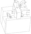
Fig. 1 is a schematic structural diagram of a multifunctional river sluice of an urban ecological river according to an embodiment of the application.
Fig. 2 is a schematic structural diagram of a power assembly according to an embodiment of the present application.
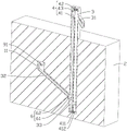
Fig. 3 is a schematic view of the internal structure of the side wall according to the embodiment of the present application.
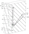
Fig. 4 is a schematic structural diagram of a connection assembly according to an embodiment of the present application.
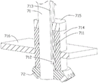
Fig. 5 is an enlarged schematic view at a in fig. 4.
FIG. 6 is a schematic view of the internal structure of a retaining ring according to an embodiment of the present application.
Description of reference numerals:
1. a base; 11. a grit chamber; 2. a side wall; 21. a gate; 22. accommodating grooves; 23. a support frame; 24. a cylinder; 25. installing a cavity; 3. a settling tube; 31. a discharge pipe; 32. a connecting channel; 33. a lifting plate; 4. a lifting assembly; 41. a first reciprocating screw rod; 411. a driving pulley; 412. a transmission belt; 42. a worm gear; 43. a worm; 431. a second pulley; 5. a power assembly; 51. positioning a rod; 511. a first pulley; 512. a first belt; 52. a propeller; 6. a blocking component; 61. a baffle plate; 62. a second reciprocating screw rod; 7. a rotating assembly; 71. rotating the rod; 711. a rotating ring; 712. a limiting block; 713. a limiting groove; 714. a positioning ring; 715. a gravity ring; 716. a fixing plate; 72. a first bevel gear; 73. a second bevel gear; 8. a connecting assembly; 81. a third reciprocating screw rod; 811. a driven pulley; 812. a butt joint plate; 82. a first rotating gear; 83. a second rotating gear; 84. a third rotating gear; 9. a transfer assembly; 91. a stirring rod; 911. a fourth pulley; 92. a spiral sheet; 93. a drive rod; 931. a third belt pulley; 932. a second belt; 94. and a third bevel gear.
Detailed Description
The present application is described in further detail below with reference to figures 1-6.
The embodiment of the application discloses multi-functional river floodgate of ecological river course in city. Referring to fig. 1, the multifunctional river sluice of the urban ecological river comprises a base 1, a side wall 2 and a gate 21 arranged in the river.
Referring to fig. 1 and 2, a base 1 is horizontally arranged, the base 1 is embedded on the inner bottom surface of a river channel, and the upper surface of the base 1 is flush with the inner bottom surface of the river channel. The side walls 2 are vertically arranged on two sides of the river channel, and the side walls 2 are fixedly connected with the base 1. Holding tank 22 has all been seted up on the side that both sides headwall 2 are close to each other, the vertical setting of holding tank 22, the cooperation of sliding of gate 21 and holding tank 22's inside wall. A supporting frame 23 is arranged between the side walls 2 on the two sides, the bottom surface of the supporting frame 23 is fixedly connected with the upper surfaces of the side walls 2, an air cylinder 24 is installed on the upper surface of the supporting frame 23, a piston rod of the air cylinder 24 penetrates through the supporting frame 23 and is fixedly connected with the upper surface of the gate 21, and a piston rod of the air cylinder 24 is matched with the supporting rod in a sliding mode.
Referring to fig. 1 and 3, a grit chamber 11 is formed in the upper surface of the base 1, the grit chamber 11 is disposed on the upstream side of the gate 21, the length direction of the grit chamber 11 is perpendicular to the flow direction of the water flow, and the cross section of the grit chamber 11 is rectangular. A settling pipe 3 vertically penetrates through the side wall 2 on one side, the settling pipe 3 is fixedly connected with the side wall 2, a discharge pipe 31 is arranged at the end part of the settling pipe 3 extending out of the side wall 2, and the discharge pipe 31 is communicated with the settling pipe 3. A connecting channel 32 is arranged between the grit chamber 11 and the sedimentation pipe 3, the connecting channel 32 is obliquely arranged, one end of the connecting channel 32 is communicated with the inner bottom surface of the grit chamber 11, and the other end of the connecting channel 32 is communicated with the bottom of the sedimentation pipe 3. In the silt in upper reaches river course got into grit chamber 11 along with rivers, silt in the grit chamber 11 got into in the sedimentation tube 3 through connecting channel 32.
Referring to fig. 2 and 3, the inner side wall of the settling tube 3 is slidably provided with a lifting plate 33, and the upper surface of the lifting plate 33 is inclined. The settling tube 3 is internally provided with a lifting assembly 4 for driving the lifting plate 33 to move, and the lifting assembly 4 comprises a first reciprocating screw rod 41, a worm wheel 42 and a worm 43. The first reciprocating screw rod 41 is vertically arranged, the bottom of the first reciprocating screw rod 41 is rotatably connected with the inner bottom surface of the settling tube 3, the top of the first reciprocating screw rod 41 is rotatably connected with the inner top surface of the settling tube 3, the first reciprocating screw rod 41 penetrates through the lifting plate 33, and the first reciprocating screw rod 41 is in threaded fit with the lifting plate 33. The worm wheel 42 is sleeved on the top of the first reciprocating screw rod 41, and the worm wheel 42 is fixedly connected with the first reciprocating screw rod 41. The worm 43 is arranged in the settling tube 3 in a penetrating way, the worm 43 is rotationally connected with the settling tube 3, and the worm 43 is meshed with the worm wheel 42.
Referring to fig. 2 and 3, the side wall 2 is provided with a power assembly 5 for driving the worm 43 to rotate, the power assembly 5 includes a positioning rod 51 and a propeller 52, the positioning rod 51 is horizontally arranged, the length direction of the positioning rod 51 is perpendicular to the flow direction of the water flow, and two ends of the positioning rod 51 are respectively rotatably connected with the side wall 2. The screw 52 is fixedly sleeved on the positioning rod 51, two screws 52 are arranged, and the two screws 52 are arranged at intervals. The end part of the positioning rod 51 close to the settling tube 3 is fixedly sleeved with a first belt wheel 511, the end part of the worm 43 extending out of the settling tube 3 is sleeved with a second belt wheel 431, the second belt wheel 431 is fixedly connected with the worm 43, and a first belt 512 is wound between the first belt wheel 511 and the second belt wheel 431. When the operator uses the air cylinder 24 to lift the gate 21, the water flow impacts the propeller 52, the propeller 52 rotates to rotate the positioning rod 51, the positioning rod 51 rotates to rotate the first belt wheel 511, the first belt wheel 511 rotates the second belt wheel 431 through the first belt 512, the second belt wheel 431 rotates to rotate the worm 43, the worm 43 rotates to rotate the worm wheel 42, the worm wheel 42 rotates to rotate the first reciprocating screw rod 41, and the lifting plate 33 reciprocates.
Referring to fig. 3 and 4, a blocking assembly 6 for closing the connecting channel 32 is arranged in the settling tube 3, the blocking assembly 6 comprises a baffle 61 and a second reciprocating screw rod 62, an installation cavity 25 is formed in the side wall 2, and the cross section of the installation cavity 25 is rectangular. The baffle 61 is arranged in the sedimentation pipe 3 in a penetrating way, and the baffle 61 is matched with the sedimentation pipe 3 in a sliding way. The second reciprocating screw rod 62 penetrates through the baffle 61, the second reciprocating screw rod 62 is in threaded fit with the baffle 61, one end of the second reciprocating screw rod 62 is rotatably connected with the settling pipe 3, and the other end of the second reciprocating screw rod 62 extends into the mounting cavity 25.
Referring to fig. 5 and 6, a rotating assembly 7 for driving the second reciprocating screw 62 to rotate is disposed in the mounting cavity 25, and the rotating assembly 7 includes a rotating rod 71, a first bevel gear 72 and a second bevel gear 73. The rotating rod 71 is vertically arranged, and the top of the rotating rod 71 is rotatably connected with the inner top surface of the mounting cavity 25. The cover is equipped with the rotating ring 711 on dwang 71, fixedly connected with stopper 712 on the inside wall of rotating ring 711, has seted up spacing groove 713 on the outer peripheral face of dwang 71, and the length direction of spacing groove 713 is unanimous with the length direction of dwang 71, and stopper 712 and the inside wall of spacing groove 713 slide fit. The first bevel gear 72 is sleeved on the rotating rod 71, the first bevel gear 72 is in sliding fit with the rotating rod 71, and the upper surface of the first bevel gear 72 is fixedly connected with the bottom surface of the rotating ring 711. The second bevel gear 73 is fixedly sleeved on the end part of the second reciprocating screw rod 62 extending to the mounting cavity 25, and the first bevel gear 72 and the second bevel gear 73 are meshed with each other.
Referring to fig. 3 and 4, a connecting assembly 8 for driving the rotating rod 71 to rotate is arranged in the installation cavity 25, the connecting assembly 8 comprises a third reciprocating screw rod 81, a first rotating gear 82, a second rotating gear 83 and a third rotating gear 84, the third reciprocating screw rod 81 is vertically arranged, the bottom of the third reciprocating screw rod 81 is rotatably connected with the inner bottom surface of the installation cavity 25, and the top of the third reciprocating screw rod 81 is rotatably connected with the inner top surface of the installation cavity 25. The bottom of the first reciprocating screw rod 41 is fixedly sleeved with a driving belt wheel 411, the bottom of the third reciprocating screw rod 81 is fixedly sleeved with a driven belt wheel 811, a transmission belt 412 is wound between the driving belt wheel 411 and the driven belt wheel 811, and the transmission belt 412 penetrates through the settling pipe 3 and the side wall 2.
Referring to fig. 4, the first rotating gear 82 is fixedly sleeved on the top of the third reciprocating screw 81, the third rotating gear 84 is fixedly sleeved on the top of the rotating rod 71, the second rotating gear 83 is disposed between the first rotating gear 82 and the third rotating gear 84, the second rotating gear 83 is rotatably connected with the inner top surface of the installation cavity 25, one side of the second rotating gear 83 is meshed with the first rotating gear 82, and the other side of the second rotating gear 83 is meshed with the third rotating gear 84.
Referring to fig. 5 and 6, a positioning ring 714 is sleeved on the rotating ring 711, the positioning ring 714 is rotatably connected with the rotating ring 711, a gravity ring 715 is fixedly connected to the positioning ring 714, the gravity ring 715 is sleeved on the rotating rod 71, and the gravity ring 715 is in sliding fit with the rotating rod 71. A fixing plate 716 is fixedly connected to the outer peripheral surface of the positioning ring 714, and the outer side wall of the fixing plate 716 is in sliding fit with the inner side wall of the mounting cavity 25. The cover is equipped with butt plate 812 on the reciprocal lead screw 81 of third, and butt plate 812 and the reciprocal lead screw 81 screw-thread fit of third, the cooperation of sliding of the lateral wall of butt plate 812 and the inside wall of installation cavity 25, and the thickness of butt plate 812 is thicker, the upper surface of butt plate 812 and the bottom surface butt of fixed plate 716.
When the first reciprocating screw rod 41 rotates, the first reciprocating screw rod 41 rotates to enable the driving pulley 411 to rotate, the driving pulley 411 rotates to enable the driven pulley 811 to rotate through the transmission belt 412, the driven pulley 811 rotates to drive the third reciprocating screw rod 81 to rotate, the third reciprocating screw rod 81 rotates to enable the first rotating gear 82 to drive on one hand, the first rotating gear 82 rotates to enable the second rotating gear 83 and the third rotating gear 84 to rotate, the third rotating gear 84 rotates to enable the rotating rod 71 to rotate, the rotating rod 71 rotates to enable the rotating ring 711 to rotate through the matching of the limiting block 712 and the limiting groove 713, the rotating ring 711 rotates to enable the second reciprocating screw rod 62 to rotate through the matching of the first bevel gear 72 and the second bevel gear 73, and then the baffle plate 61 moves; the third reciprocating screw 81 rotates on the other hand to move the abutting plate 812, when the abutting plate 812 moves upwards to abut against the fixing plate 716, the connecting channel 32 is blocked by the baffle 61 at the moment, when the abutting plate 812 continues moving upwards, the abutting plate 812 drives the fixing plate 716 to move, the fixing rod drives the positioning ring 714 to move, the positioning ring 714 enables the rotating ring 711 and the first bevel gear 72 to move, so that the first bevel gear 72 is separated from the second bevel gear 73, the second reciprocating screw 62 stops rotating, and silt in the connecting channel 32 is prevented from continuing to enter the settling tube 3. When the abutting plate 812 is downward, the positioning ring 714 is synchronously lowered under the gravity of the gravity ring 715, when the first bevel gear 72 moves to be re-engaged with the second bevel gear 73, the upper surface of the lifting plate 33 is flush with the lowest point of the connecting channel 32, and the second bevel gear 73 is matched with the first bevel gear 72 to enable the second reciprocating screw rod 62 to drive the baffle 61 to move, so that the silt in the connecting channel 32 is further arranged in the settling tube 3.
Referring to fig. 1 and 5, a transfer assembly 9 is arranged in the grit chamber 11, the transfer assembly 9 includes a stirring rod 91, a spiral piece 92, a driving rod 93 and a third bevel gear 94, the stirring rod 91 is horizontally arranged, the length of the stirring rod 91 is consistent with that of the grit chamber 11, and the end of the stirring rod 91 is rotatably connected with the inner end surface of the grit chamber 11. The spiral piece 92 is spirally arranged around the axis of the stirring rod 91, and the spiral piece 92 is fixedly connected with the stirring rod 91. The driving rod 93 is horizontally arranged, the axis of the driving rod 93 coincides with the axis of the second reciprocating screw rod 62, the third bevel gear 94 is fixedly sleeved on the end part of the driving rod 93, the other end, far away from the third bevel gear 94, of the driving rod 93 is rotatably connected with the inner side wall of the mounting cavity 25, and the third bevel gear 94 is meshed with the first bevel gear 72.
Referring to fig. 4 and 5, a third pulley 931 is fixedly sleeved on the driving rod 93, a fourth pulley 911 is fixedly sleeved on the end portion of the stirring rod 91 extending to the base 1, and a second belt 932 is wound between the third pulley 931 and the fourth pulley 911. When first bevel gear 72 meshes with second bevel gear 73 and third bevel gear 94 simultaneously, baffle 61 is complete shutoff interface channel 32 not, at this moment, third bevel gear 94 rotates and makes actuating lever 93 rotate, actuating lever 93 rotates and makes third band pulley 931 rotate, third band pulley 931 rotates and makes fourth band pulley 911 rotate through second belt 932, thereby make puddler 91 and flight 92 rotate, finally make the silt of grit chamber 11 get into interface channel 32 fast in, make things convenient for operating personnel to clear up the silt in grit chamber 11.
The implementation principle of the multifunctional river gate of the urban ecological river channel in the embodiment of the application is as follows: when gate 21 is in the open mode, the silt of upper reaches enters into grit chamber 11 along with the rivers in, operating personnel makes silt in the grit chamber 11 get into in the connecting channel 32 through transporting subassembly 9, silt in the connecting channel 32 finally gets into in the sedimentation pipe 3, operating personnel utilizes lifting unit 4 drive lifting plate 33 to remove along the direction of height of sedimentation pipe 3, and then makes the silt that gets into in the sedimentation pipe 3 discharge through discharge pipe 31, be favorable to preventing that the silt in the river course from depositing in sluice department.
The above embodiments are preferred embodiments of the present application, and the protection scope of the present application is not limited by the above embodiments, so: all equivalent changes made according to the structure, shape and principle of the present application shall be covered by the protection scope of the present application.
Claims (8)
1. The utility model provides a multi-functional river floodgate of ecological river course in city, including set up in side wall (2) of river course both sides, set up base (1) on the bottom in the river course, set up in support frame (23) on base (1) and install in gate (21) on support frame (23), its characterized in that: the sand setting tank (11) has been seted up on base (1), vertical sedimentation pipe (3) of wearing to be equipped with on side wall (2), sedimentation pipe (3) through connect passage (32) with sand setting tank (11) are linked together, the intercommunication has discharge pipe (31) on sedimentation pipe (3) extend the tip of side wall (2), be provided with in sand setting tank (11) and be used for transporting transportation subassembly (9) of silt, it is provided with lifting plate (33) to slide on the inside wall of sedimentation pipe (3), be provided with on sedimentation pipe (3) and be used for the drive lifting unit (4) that lifting plate (33) removed.
2. The multifunctional river sluice of the urban ecological river channel according to claim 1, wherein the multifunctional river sluice comprises: lifting unit (4) are including vertical wear to locate first reciprocal lead screw (41), the fixed cover in side wall (2) is located worm wheel (42) on first reciprocal lead screw (41) and wear to locate worm (43) in side wall (2), first reciprocal lead screw (41) are passed lifting plate (33) and with lifting plate (33) screw-thread fit, worm (43) with worm wheel (42) intermeshing, be provided with on side wall (2) and be used for the drive worm (43) pivoted power component (5).
3. The multifunctional river sluice of the urban ecological river channel according to claim 2, wherein: the power assembly (5) comprises a positioning rod (51) arranged on the side wall (2) in a penetrating mode, a screw propeller (52) arranged on the positioning rod (51) in a fixed mode, a first belt wheel (511) is fixedly arranged on the positioning rod (51) in a fixed mode, a second belt wheel (431) is fixedly arranged on the worm (43) in a fixed mode, and a first belt (512) is arranged between the first belt wheel (511) and the second belt wheel (431) in a winding mode.
4. The multifunctional river sluice of the urban ecological river channel according to claim 2, wherein: be provided with in sedimentation pipe (3) and be used for sealing connect the subassembly (6) that blocks of passageway (32), block subassembly (6) including sliding to wear to locate baffle (61) in sedimentation pipe (3), wear to locate reciprocal lead screw (62) of second in side wall (2), reciprocal lead screw (62) of second penetrate in baffle (61) and with baffle (61) screw-thread fit, be provided with in side wall (2) and be used for the drive the rotatory runner assembly (7) of reciprocal lead screw (62) of second.
5. The multifunctional river sluice of the urban ecological river channel according to claim 4, wherein the multifunctional river sluice comprises: seted up installation cavity (25) in side wall (2), runner assembly (7) including rotate install in dwang (71) on the top surface in installation cavity (25), set up in first bevel gear (72), fixed cover on dwang (71) are located the reciprocal lead screw of second (62) extend to second bevel gear (73) on installation cavity (25) tip, first bevel gear (72) with second bevel gear (73) intermeshing, be provided with in installation cavity (25) and be used for the drive dwang (71) rotatory coupling assembling (8).
6. The multifunctional river sluice of the urban ecological river channel, according to claim 5, is characterized in that: the connecting assembly (8) comprises a third reciprocating screw rod (81) rotatably arranged on the inner top surface of the mounting cavity (25), a first rotating gear (82) fixedly sleeved on the third reciprocating screw rod (81), a second rotating gear (83) rotatably arranged on the inner top surface of the mounting cavity (25) and a third rotating gear (84) fixedly sleeved on the rotating rod (71), the second rotating gear (83) is disposed between the first rotating gear (82) and the second rotating gear (83), and the second rotating gear (83) is meshed with the first rotating gear (82) and the third rotating gear (84) respectively, a driving belt wheel (411) is fixedly sleeved on the first reciprocating screw rod (41), a driven belt wheel (811) is fixedly sleeved on the third reciprocating screw rod (81), a transmission belt (412) is wound between the driving pulley (411) and the driven pulley (811).
7. The multifunctional river sluice of the urban ecological river channel according to claim 6, wherein the multifunctional river sluice comprises: sliding sleeve is equipped with swivel becket (711) on dwang (71), fixedly connected with stopper (712) on the inside wall of swivel becket (711), seted up on dwang (71) be used for with stopper (712) complex spacing groove (713) that slides, swivel becket (711) with first bevel gear (72) fixed connection, the cover is equipped with holding ring (714) on swivel becket (711), holding ring (714) with swivel becket (711) rotates to be connected, fixedly connected with gravity ring (715) on holding ring (714), just fixedly connected with fixed plate (716) on holding ring (714), the cover is equipped with on the reciprocal lead screw of third (81) be used for with reciprocal lead screw of third (81) screw-thread fit's butt joint board (812), butt joint board (812) with fixed plate (716) butt joint.
8. The multifunctional river sluice of the urban ecological river channel, according to claim 5, is characterized in that: transport subassembly (9) including wearing to locate puddler (91) and fixed connection on the terminal surface in grit chamber (11) on puddler (91) flight (92), rotation install in actuating lever (93), fixed cover on installation cavity (25) inside wall are located third bevel gear (94) on actuating lever (93), third bevel gear (94) with first bevel gear (72) intermeshing, just fixed cover is equipped with third band pulley (931) on actuating lever (93), fixed cover is equipped with fourth band pulley (911) on puddler (91), third band pulley (931) with around being equipped with second belt (932) between fourth band pulley (911).
Priority Applications (1)
| Application Number | Priority Date | Filing Date | Title |
|---|---|---|---|
| CN202210082678.3A CN114508079B (en) | 2022-01-24 | 2022-01-24 | Urban ecological river channel multifunctional river gate |
Applications Claiming Priority (1)
| Application Number | Priority Date | Filing Date | Title |
|---|---|---|---|
| CN202210082678.3A CN114508079B (en) | 2022-01-24 | 2022-01-24 | Urban ecological river channel multifunctional river gate |
Publications (2)
| Publication Number | Publication Date |
|---|---|
| CN114508079A true CN114508079A (en) | 2022-05-17 |
| CN114508079B CN114508079B (en) | 2024-02-23 |
Family
ID=81549942
Family Applications (1)
| Application Number | Title | Priority Date | Filing Date |
|---|---|---|---|
| CN202210082678.3A Active CN114508079B (en) | 2022-01-24 | 2022-01-24 | Urban ecological river channel multifunctional river gate |
Country Status (1)
| Country | Link |
|---|---|
| CN (1) | CN114508079B (en) |
Cited By (3)
| Publication number | Priority date | Publication date | Assignee | Title |
|---|---|---|---|---|
| CN115404825A (en) * | 2022-08-24 | 2022-11-29 | 江西容大建工集团有限公司 | Over-and-under type water sluicegate for hydraulic engineering |
| CN117822623A (en) * | 2024-02-23 | 2024-04-05 | 福建得乾集团有限责任公司 | A diversion cofferdam |
| CN119041358A (en) * | 2024-10-31 | 2024-11-29 | 中国电建集团贵阳勘测设计研究院有限公司 | Hydraulic engineering is with overflow dam that has flood discharge function |
Citations (7)
| Publication number | Priority date | Publication date | Assignee | Title |
|---|---|---|---|---|
| JPH1089299A (en) * | 1996-09-19 | 1998-04-07 | Kubota Corp | Pump station drainage and sediment removal method |
| JP2004270256A (en) * | 2003-03-07 | 2004-09-30 | Ishikawajima Harima Heavy Ind Co Ltd | Sand discharging method and sand discharging device for reservoir |
| CN210887142U (en) * | 2019-10-18 | 2020-06-30 | 湖南省瑞大工程建设有限公司 | Gate for water conservancy ditch |
| CN212896113U (en) * | 2020-05-29 | 2021-04-06 | 山东海建水利工程有限公司 | A waterproof and drainage device for water conservancy engineering construction |
| CN213173606U (en) * | 2020-04-30 | 2021-05-11 | 武汉圣禹排水系统有限公司 | Weir gate slag cleaning system |
| CN213538900U (en) * | 2020-09-07 | 2021-06-25 | 中国电建集团昆明勘测设计研究院有限公司 | Desilting and sand-discharging device for steel dam |
| CN215165355U (en) * | 2021-06-18 | 2021-12-14 | 诸城市河道维护中心 | Hydraulic engineering water inlet rubbish cleaning device |
-
2022
- 2022-01-24 CN CN202210082678.3A patent/CN114508079B/en active Active
Patent Citations (7)
| Publication number | Priority date | Publication date | Assignee | Title |
|---|---|---|---|---|
| JPH1089299A (en) * | 1996-09-19 | 1998-04-07 | Kubota Corp | Pump station drainage and sediment removal method |
| JP2004270256A (en) * | 2003-03-07 | 2004-09-30 | Ishikawajima Harima Heavy Ind Co Ltd | Sand discharging method and sand discharging device for reservoir |
| CN210887142U (en) * | 2019-10-18 | 2020-06-30 | 湖南省瑞大工程建设有限公司 | Gate for water conservancy ditch |
| CN213173606U (en) * | 2020-04-30 | 2021-05-11 | 武汉圣禹排水系统有限公司 | Weir gate slag cleaning system |
| CN212896113U (en) * | 2020-05-29 | 2021-04-06 | 山东海建水利工程有限公司 | A waterproof and drainage device for water conservancy engineering construction |
| CN213538900U (en) * | 2020-09-07 | 2021-06-25 | 中国电建集团昆明勘测设计研究院有限公司 | Desilting and sand-discharging device for steel dam |
| CN215165355U (en) * | 2021-06-18 | 2021-12-14 | 诸城市河道维护中心 | Hydraulic engineering water inlet rubbish cleaning device |
Cited By (4)
| Publication number | Priority date | Publication date | Assignee | Title |
|---|---|---|---|---|
| CN115404825A (en) * | 2022-08-24 | 2022-11-29 | 江西容大建工集团有限公司 | Over-and-under type water sluicegate for hydraulic engineering |
| CN115404825B (en) * | 2022-08-24 | 2023-07-21 | 江西容大建工集团有限公司 | Lifting water conservancy gate for water conservancy engineering |
| CN117822623A (en) * | 2024-02-23 | 2024-04-05 | 福建得乾集团有限责任公司 | A diversion cofferdam |
| CN119041358A (en) * | 2024-10-31 | 2024-11-29 | 中国电建集团贵阳勘测设计研究院有限公司 | Hydraulic engineering is with overflow dam that has flood discharge function |
Also Published As
| Publication number | Publication date |
|---|---|
| CN114508079B (en) | 2024-02-23 |
Similar Documents
| Publication | Publication Date | Title |
|---|---|---|
| CN114508079B (en) | Urban ecological river channel multifunctional river gate | |
| CN112411549B (en) | Cast-in-place pile steel casing hole sweeping equipment | |
| CN214118592U (en) | Novel immersible pump mechanism of intaking | |
| CN210887142U (en) | Gate for water conservancy ditch | |
| CN108824385A (en) | A kind of energy-saving and environment-friendly device for cleaning dirt on surface of water | |
| CN112459019A (en) | Automatic gate | |
| CN109939775B (en) | Coal washing device with anti-blocking function | |
| CN209679566U (en) | Experimental device for oil-water separation | |
| CN113915142B (en) | Drainage equipment with water flow dispersing components for tunnel construction | |
| CN115738403A (en) | Sedimentation tank bottom sludge suction device | |
| CN113774866A (en) | Flow regulating equipment for spillway | |
| CN220133081U (en) | Water conservancy environmental protection integrated pump station | |
| CN116816284B (en) | Highway construction operation digs soon and bores device | |
| CN219298299U (en) | River channel dredging equipment | |
| CN116950161A (en) | An environmentally friendly dredging equipment for river regulation projects | |
| KR20160022517A (en) | A Sludge discharge apparatus of rotary type for a settling basin having waterwheel | |
| CN214783712U (en) | Water retaining gate structure | |
| CN115059030A (en) | Device for cleaning suspended garbage in water body at drainage gate | |
| CN114870435A (en) | A rotary oil-draining marine oil-water separation device | |
| CN219992373U (en) | Water conservancy gate equipment with clearance structure | |
| CN223782396U (en) | A water diversion device for water conservancy projects | |
| CN112049213A (en) | Municipal administration rainwater recycle device | |
| CN217627748U (en) | River pollution administers ecological structure | |
| CN113175049A (en) | Drainage system design structure of landscape garden | |
| CN222400375U (en) | A floating object collection structure |
Legal Events
| Date | Code | Title | Description |
|---|---|---|---|
| PB01 | Publication | ||
| PB01 | Publication | ||
| SE01 | Entry into force of request for substantive examination | ||
| SE01 | Entry into force of request for substantive examination | ||
| GR01 | Patent grant | ||
| GR01 | Patent grant |