CN114508014A - Side wall unequal-height U-shaped groove structure suitable for road - Google Patents

Side wall unequal-height U-shaped groove structure suitable for road Download PDF

Info

Publication number
CN114508014A
CN114508014A CN202210277637.XA CN202210277637A CN114508014A CN 114508014 A CN114508014 A CN 114508014A CN 202210277637 A CN202210277637 A CN 202210277637A CN 114508014 A CN114508014 A CN 114508014A
Authority
CN
China
Prior art keywords
side wall
road
shaped groove
height
ditch
Prior art date
Legal status (The legal status is an assumption and is not a legal conclusion. Google has not performed a legal analysis and makes no representation as to the accuracy of the status listed.)
Pending
Application number
CN202210277637.XA
Other languages
Chinese (zh)
Inventor
王亚坤
孙爱斌
张国祥
辛建忠
郑永红
卢业旭
李超
何宏伟
张雪磊
陈东升
周剑
李婧
郑威
吴海刚
于进庆
管朝鹏
赵津茂
Current Assignee (The listed assignees may be inaccurate. Google has not performed a legal analysis and makes no representation or warranty as to the accuracy of the list.)
China Railway Design Corp
Original Assignee
China Railway Design Corp
Priority date (The priority date is an assumption and is not a legal conclusion. Google has not performed a legal analysis and makes no representation as to the accuracy of the date listed.)
Filing date
Publication date
Application filed by China Railway Design Corp filed Critical China Railway Design Corp
Priority to CN202210277637.XA priority Critical patent/CN114508014A/en
Publication of CN114508014A publication Critical patent/CN114508014A/en
Pending legal-status Critical Current

Links

Images

Classifications

    • E—FIXED CONSTRUCTIONS
    • E01—CONSTRUCTION OF ROADS, RAILWAYS, OR BRIDGES
    • E01C—CONSTRUCTION OF, OR SURFACES FOR, ROADS, SPORTS GROUNDS, OR THE LIKE; MACHINES OR AUXILIARY TOOLS FOR CONSTRUCTION OR REPAIR
    • E01C3/00—Foundations for pavings
    • E—FIXED CONSTRUCTIONS
    • E01—CONSTRUCTION OF ROADS, RAILWAYS, OR BRIDGES
    • E01C—CONSTRUCTION OF, OR SURFACES FOR, ROADS, SPORTS GROUNDS, OR THE LIKE; MACHINES OR AUXILIARY TOOLS FOR CONSTRUCTION OR REPAIR
    • E01C11/00—Details of pavings
    • E01C11/22—Gutters; Kerbs ; Surface drainage of streets, roads or like traffic areas
    • E01C11/224—Surface drainage of streets
    • E01C11/227—Gutters; Channels ; Roof drainage discharge ducts set in sidewalks
    • E—FIXED CONSTRUCTIONS
    • E01—CONSTRUCTION OF ROADS, RAILWAYS, OR BRIDGES
    • E01C—CONSTRUCTION OF, OR SURFACES FOR, ROADS, SPORTS GROUNDS, OR THE LIKE; MACHINES OR AUXILIARY TOOLS FOR CONSTRUCTION OR REPAIR
    • E01C3/00—Foundations for pavings
    • E01C3/06—Methods or arrangements for protecting foundations from destructive influences of moisture, frost or vibration
    • E—FIXED CONSTRUCTIONS
    • E02—HYDRAULIC ENGINEERING; FOUNDATIONS; SOIL SHIFTING
    • E02D—FOUNDATIONS; EXCAVATIONS; EMBANKMENTS; UNDERGROUND OR UNDERWATER STRUCTURES
    • E02D17/00—Excavations; Bordering of excavations; Making embankments
    • E02D17/02—Foundation pits
    • E02D17/04—Bordering surfacing or stiffening the sides of foundation pits
    • E—FIXED CONSTRUCTIONS
    • E02—HYDRAULIC ENGINEERING; FOUNDATIONS; SOIL SHIFTING
    • E02D—FOUNDATIONS; EXCAVATIONS; EMBANKMENTS; UNDERGROUND OR UNDERWATER STRUCTURES
    • E02D3/00—Improving or preserving soil or rock, e.g. preserving permafrost soil
    • E02D3/02—Improving by compacting
    • E02D3/10—Improving by compacting by watering, draining, de-aerating or blasting, e.g. by installing sand or wick drains
    • E—FIXED CONSTRUCTIONS
    • E03—WATER SUPPLY; SEWERAGE
    • E03F—SEWERS; CESSPOOLS
    • E03F3/00—Sewer pipe-line systems
    • E03F3/04—Pipes or fittings specially adapted to sewers
    • E03F3/046—Open sewage channels
    • Y—GENERAL TAGGING OF NEW TECHNOLOGICAL DEVELOPMENTS; GENERAL TAGGING OF CROSS-SECTIONAL TECHNOLOGIES SPANNING OVER SEVERAL SECTIONS OF THE IPC; TECHNICAL SUBJECTS COVERED BY FORMER USPC CROSS-REFERENCE ART COLLECTIONS [XRACs] AND DIGESTS
    • Y02—TECHNOLOGIES OR APPLICATIONS FOR MITIGATION OR ADAPTATION AGAINST CLIMATE CHANGE
    • Y02A—TECHNOLOGIES FOR ADAPTATION TO CLIMATE CHANGE
    • Y02A30/00—Adapting or protecting infrastructure or their operation
    • Y02A30/60—Planning or developing urban green infrastructure

Landscapes

  • Engineering & Computer Science (AREA)
  • Structural Engineering (AREA)
  • Civil Engineering (AREA)
  • Life Sciences & Earth Sciences (AREA)
  • Architecture (AREA)
  • Mining & Mineral Resources (AREA)
  • General Life Sciences & Earth Sciences (AREA)
  • Paleontology (AREA)
  • General Engineering & Computer Science (AREA)
  • Soil Sciences (AREA)
  • Environmental & Geological Engineering (AREA)
  • Agronomy & Crop Science (AREA)
  • Health & Medical Sciences (AREA)
  • Hydrology & Water Resources (AREA)
  • Public Health (AREA)
  • Water Supply & Treatment (AREA)
  • Road Paving Structures (AREA)
  • Sewage (AREA)

Abstract

本发明公开了一种适用于道路的边墙不等高U型槽结构,包括混凝土底板,以及底板的左边墙和右边墙,左边墙的高度高于右边墙高度。在左边墙内侧设置有边沟或盖板沟,在左边墙外侧且沿道路纵向铺设纵向透水管,沿道路纵向设置多根竖向透水管的底端与连通,沿道路纵向前后间隔设置的多根横向水管的一端与纵向透水管的下部连通,另一端与边沟或盖板沟下部连通。通过纵横向排水系统排泄道路U型槽边墙外侧地下水,降低了边墙外侧承受的水压力,对边墙尺寸进行优化,降低工程投资。该边墙不等高U型槽作为一种新型的结构形式,能够适用于各种地形。

Figure 202210277637

The invention discloses a side wall unequal height U-shaped groove structure suitable for roads, comprising a concrete bottom plate, left and right walls of the bottom plate, and the height of the left wall is higher than that of the right wall. A side ditch or a cover ditch is arranged on the inner side of the left wall, and longitudinal permeable pipes are laid on the outer side of the left wall and along the longitudinal direction of the road. One end of the horizontal water pipe is communicated with the lower part of the longitudinal water permeable pipe, and the other end is communicated with the lower part of the side ditch or the cover plate ditch. The groundwater outside the U-shaped groove side wall of the road is drained through the vertical and horizontal drainage system, which reduces the water pressure on the outside of the side wall, optimizes the size of the side wall, and reduces the project investment. As a new type of structure, the unequal height U-shaped groove of the side wall can be applied to various terrains.

Figure 202210277637

Description

Side wall unequal-height U-shaped groove structure suitable for road
Technical Field
The invention relates to a road retaining structure, in particular to a side wall unequal-height U-shaped groove structure.
Background
The overpass projects for passing high-speed railway bridges or high-grade highway bridges under highways or municipal roads are more and more, the U-shaped groove supporting and blocking structure is also called a closed cutting structure, the U-shaped groove supporting and blocking structure is more applied to underground water level and downward digging road sections without slope release, and the U-shaped groove supporting and blocking structure has the characteristics of good waterproof performance, high rigidity, good durability, good slope collecting and blocking effect and the like.
The U-shaped groove is generally formed by side walls with equal heights on two sides and a bottom plate, the side walls of the U-shaped groove can be generally regarded as a single cantilever structure, the structure needs to bear water pressure and soil pressure behind the wall, and because the side walls of the conventional U-shaped groove structure are the same in height and bear the same water pressure and soil pressure in the horizontal direction, the influence of horizontal sliding is not considered in the design process of the general U-shaped groove. However, in practical engineering, because the structural design of the U-shaped groove is combined with site terrain conditions, the situation that the height difference of the ground on the two sides of the U-shaped groove is large often occurs, if the U-shaped groove is made into a side wall U-shaped groove with equal height, the soil body needs to be filled back outside the side wall of the U-shaped groove on the side with lower ground height to ensure that the water and soil pressures on the two sides are consistent, and the U-shaped groove is prevented from moving laterally. Simultaneously, the side walls on the two sides need to consider water and soil pressure according to the highest soil filling height, the side walls are large in size, economic waste is caused to a certain degree, and the U-shaped groove is not effectively combined with the surrounding earth surface, so that the appearance is influenced.
Disclosure of Invention
The invention aims to overcome the defects of the prior art and provide a side wall unequal-height U-shaped groove structure which can ensure that the U-shaped groove does not move laterally, reduce the engineering investment, is tightly combined with the surrounding terrain and has stronger aesthetic property.
In order to achieve the purpose, the invention adopts the technical scheme that:
the side wall unequal-height U-shaped groove structure suitable for the road comprises a concrete base plate arranged below a road surface, wherein the bottom surface of the concrete base plate is of a convex tenon structure; a left side wall and a right side wall are respectively arranged on the left side and the right side of the concrete substrate, the top surfaces of the left side wall and the right side wall are higher than the ground, the ground elevation at the left side wall is higher than the ground elevation at the right side wall, the height of the left side wall is higher than that of the right side wall, a U-shaped groove is formed among the left side wall, the concrete substrate and the right side wall, and the height of the left side wall and the height of the right side wall are set to be that surface water cannot enter the U-shaped groove;
the concrete foundation structure is characterized in that a side ditch or a cover plate ditch is arranged on the top surface of a concrete substrate on the inner side of a left side wall, longitudinal permeable pipes are longitudinally laid on the outer side of the left side wall along a road, the bottom ends of the vertical permeable pipes longitudinally arranged along the road at intervals are communicated with the longitudinal permeable pipes, the vertical permeable pipes are arranged along the vertical direction, one ends of the horizontal water pipes longitudinally arranged along the road at intervals are communicated with the lower parts of the longitudinal permeable pipes, the other ends of the horizontal water pipes are communicated with the lower parts of the side ditch or the cover plate ditch, the horizontal water pipes are inclined downwards to one side of the side ditch or the cover plate ditch, a plurality of permeable holes are formed in the outer wall of the upper part of the longitudinal permeable pipe, and a plurality of permeable holes are formed in the side walls of the vertical permeable pipes far away from the left side wall; the sand-gravel reverse filtering layer is backfilled at the outer wall of the left side wall, a rammed clay water sealing layer is arranged at the top of the sand-gravel reverse filtering layer, and the top surface of the rammed clay water sealing layer is parallel to the ground.
Compared with the prior art, the invention has the following beneficial effects:
(1) underground water outside the side wall of the road is drained through the longitudinal and transverse drainage systems, so that the water pressure borne by the outer side of the side wall is reduced, the size of the side wall can be optimized, and the engineering investment is reduced. The structure is also suitable for the conventional U-shaped groove structure with equal height of the side wall.
(2) Through reducing the water pressure of side wall one side, guarantee that the horizontal thrust that both sides side wall bore can not differ too much, can reduce the horizontal thrust that U type groove bore.
(3) Through setting up the protruding falcon of certain quantity, increased the cling compound performance in U type groove.
(4) The unequal-height U-shaped groove of the side wall can be suitable for various terrains, has a very wide engineering application prospect, and has wide application space and popularization and application values in the construction of high-speed rails, expressways, even municipal administration, buildings and the like in China.
Drawings
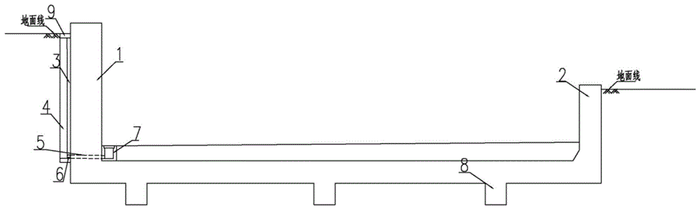
FIG. 1 is a sectional view of a non-uniform U-shaped groove structure of a side wall for a road according to the present invention;
fig. 2 is a plan view of a non-uniform U-shaped groove structure of a side wall suitable for roads.
Detailed Description
The invention is described in further detail below with reference to the figures and specific examples. It should be understood that the specific embodiments described herein are merely illustrative of the invention and are not intended to limit the invention.
The structure of the invention can be applied to the road sections with larger ground elevation difference or limited thickness of the side wall of the U-shaped groove.
As shown in the attached drawings, the unequal-height U-shaped groove structure suitable for the side walls of the roads comprises a concrete base plate arranged below the road surface, and a convex tenon structure 8 is arranged on the bottom surface of the concrete base plate.
Left side, the right side of concrete substrate be provided with left side wall 1 and right wall 2 respectively, the top surface of left side wall 1 and right wall 2 be higher than ground, 1 ground elevation of department of left side wall be higher than right wall department ground elevation, left side wall 1 highly be higher than right wall 2 height, form U type groove between left side wall 1, concrete substrate and the right wall 2, highly setting up of left side wall 1 and right wall 2 can not get into U type inslot for surface water.
Be provided with side ditch or apron ditch 7 on the top surface of the concrete substrate of 1 inboard of left side wall 1 outside and vertically laid along the road and vertically laid vertical pipe 6 of permeating water, the bottom of the vertical many vertical pipes 3 of permeating water that the interval set up around along the road is vertical with vertically permeate water pipe 6 intercommunication, many vertical pipes 3 of permeating water set up along vertical direction, the one end of the vertical many horizontal water pipes 5 that the interval set up around along the road with vertically permeate water pipe 6's lower part intercommunication and the other end and side ditch or apron ditch 7 lower part intercommunication and many horizontal water pipes 5 to side ditch or apron ditch 7 one side downward sloping, guarantee certain drainage longitudinal gradient. The horizontal water pipe 5 is arranged before the left side wall 1 is poured, and the bottom elevation of the horizontal water pipe 5 is higher than the bottom elevation of the side ditch or the cover plate ditch by 0.2 m. The outer wall of the upper part of the longitudinal permeable pipe 6 is provided with a plurality of permeable holes, and the side wall of one side of the left side wall 1 far away from the vertical permeable pipes 3 is provided with a plurality of permeable holes.
Determining the distance between two adjacent transverse water pipes 5 according to the horizontal water and soil pressure borne by the left side wall 1 and the right side wall 2 and the permeability of the surrounding soil, wherein the distance is preferably 2m-4 m; and simultaneously determining the setting height of the vertical permeable pipe 3. The vertical permeable pipe 3 and the longitudinal permeable pipe 6 are preferably made of permeable PVC pipe or other permeable pipes, and the pipe diameter is determined according to the size of the ground water to be removed, preferably 10-15 cm. The pipe diameter of horizontal water pipe 5 should be more than or equal to the pipe diameter of the pipe 6 of vertically permeating water in this structure, and the pipe diameter more than or equal to the pipe diameter of the vertical pipe 3 of permeating water of the pipe 6 of vertically permeating water.
The outer wall of the left side wall 1 is back filled with a sand-pebble back-filtering layer 4, and the thickness of the sand-pebble back-filtering layer is preferably not less than 50 cm.
The top of the sand-gravel inverted filter layer is provided with a rammed clay water sealing layer 9, the top surface of the rammed clay water sealing layer is flush with the ground to prevent surface water from entering, the clay water sealing layer is preferably paved to the outer side of the left side wall by 0.6-1.0m, and the thickness is preferably 0.3-0.6 m.
The construction process of the structure is as follows:
1. excavating a road foundation pit, and then pouring a concrete bottom plate, wherein the thickness of the concrete bottom plate is determined according to the anti-floating design of the structure by combining the road longitudinal section;
2. installing a transverse water pipe 5;
3. a vertical permeable pipe 3 and a longitudinal permeable pipe 6.
4. And (3) backfilling the gravel reverse filtering layer outside the left side wall 1, and avoiding the drain pipe from being damaged when the reverse filtering layer is backfilled and rolled.
5. A rammed clay water sealing layer is arranged at the top of the sand gravel reverse filtering layer to prevent surface water from entering;
6. according to getting rid of behind the groundwater according to the difference of the horizontal force that left side wall 1 and right wall 2 bore, confirm size and the quantity that need set up protruding falcon structure through the requirement of anti-skidding factor of safety, the outside distance of the protruding falcon structure central line distance corresponding side wall in the left side should not be less than 2m, protruding falcon cross section should be square.
7. After the side walls and the bottom plate of the U-shaped groove are poured, water in the side ditch or the cover plate ditch is guided to the lowest point of the downward dug road to enter a water collecting well or a transverse drainage ditch and is drained away through a pump station.
The present invention is not limited to the above-described embodiments. The foregoing description of the specific embodiments is intended to describe and illustrate the technical solutions of the present invention, and the above specific embodiments are merely illustrative and not restrictive. Those skilled in the art can make many changes and modifications to the invention without departing from the spirit and scope of the invention as defined in the appended claims.

Claims (8)

1. The utility model provides a side wall U type groove structure that varies height suitable for road, is including setting up the concrete substrate in the road surface below, its characterized in that: the bottom surface of the concrete base plate is provided with a convex falcon structure (8); a left side wall (1) and a right side wall (2) are respectively arranged on the left side and the right side of the concrete substrate, the top surfaces of the left side wall and the right side wall are higher than the ground, the ground elevation at the left side wall is higher than the ground elevation at the right side wall, the height of the left side wall is higher than that of the right side wall, a U-shaped groove is formed among the left side wall, the concrete substrate and the right side wall, and the height of the left side wall and the height of the right side wall are set to be that surface water cannot enter the U-shaped groove;
the concrete foundation slab is characterized in that a side ditch or a cover plate ditch (7) is arranged on the top surface of a concrete substrate on the inner side of a left side wall, longitudinal pervious pipes (6) are longitudinally laid on the outer side of the left side wall along a road, the bottom ends of a plurality of vertical pervious pipes longitudinally arranged along the road at intervals are communicated with the longitudinal pervious pipes, a plurality of vertical pervious pipes (3) are arranged along the vertical direction, one ends of a plurality of transverse water pipes (5) longitudinally arranged along the road at intervals are communicated with the lower part of the longitudinal pervious pipes (6), the other ends of the transverse water pipes are communicated with the lower part of the side ditch or the cover plate ditch, the transverse water pipes (5) are inclined downwards towards one side of the side ditch or the cover plate ditch, a plurality of pervious holes are formed in the outer wall of the upper part of the longitudinal pervious pipes, and a plurality of pervious holes are formed in the side walls of the vertical pervious pipes far away from the left side wall; the sand-gravel reverse filtering layer is backfilled at the outer wall of the left side wall, a rammed clay water sealing layer is arranged at the top of the sand-gravel reverse filtering layer, and the top surface of the rammed clay water sealing layer is parallel to the ground.
2. The unequal-height U-shaped groove structure suitable for the side wall of the road as claimed in claim 1, wherein: the bottom elevation of the transverse water pipe is higher than the bottom elevation of the side ditch or the cover plate ditch by 0.2 m.
3. The unequal-height U-shaped groove structure suitable for the side wall of the road as claimed in claim 1 or 2, wherein: the distance between two adjacent transverse water pipes 5 is 2m-4 m.
4. The unequal-height U-shaped groove structure suitable for the side wall of the road as claimed in claim 3, wherein: the pipe diameter of the transverse water pipe is larger than or equal to that of the longitudinal permeable pipe, and the pipe diameter of the longitudinal permeable pipe is larger than or equal to that of the vertical permeable pipe.
5. The unequal-height U-shaped groove structure suitable for the side wall of the road as claimed in claim 4, wherein: the pipe diameters of the vertical permeable pipe and the longitudinal permeable pipe are 10-15 cm.
6. The unequal-height U-shaped groove structure suitable for the side wall of the road as claimed in claim 4, wherein: the thickness of the sand-pebble inverted filter layer is not less than 50 cm.
7. The unequal-height U-shaped groove structure suitable for the side wall of the road as claimed in claim 6, wherein: the clay water sealing layer is preferably paved to the outer side of the left side wall by 0.6-1.0m, and the thickness is 0.3-0.6 m.
8. The unequal-height U-shaped groove structure suitable for the side wall of the road as claimed in claim 7, wherein: protruding falcon structure central line distance corresponding side wall of left side outside is not less than 2m, and protruding falcon cross section is square.
CN202210277637.XA 2022-03-21 2022-03-21 Side wall unequal-height U-shaped groove structure suitable for road Pending CN114508014A (en)

Priority Applications (1)

Application Number Priority Date Filing Date Title
CN202210277637.XA CN114508014A (en) 2022-03-21 2022-03-21 Side wall unequal-height U-shaped groove structure suitable for road

Applications Claiming Priority (1)

Application Number Priority Date Filing Date Title
CN202210277637.XA CN114508014A (en) 2022-03-21 2022-03-21 Side wall unequal-height U-shaped groove structure suitable for road

Publications (1)

Publication Number Publication Date
CN114508014A true CN114508014A (en) 2022-05-17

Family

ID=81554950

Family Applications (1)

Application Number Title Priority Date Filing Date
CN202210277637.XA Pending CN114508014A (en) 2022-03-21 2022-03-21 Side wall unequal-height U-shaped groove structure suitable for road

Country Status (1)

Country Link
CN (1) CN114508014A (en)

Citations (6)

* Cited by examiner, † Cited by third party
Publication number Priority date Publication date Assignee Title
JPH10102572A (en) * 1996-08-05 1998-04-21 Tetsuji Shiromichi Surefooting gutter execution method for forest road
CN212801628U (en) * 2020-04-13 2021-03-26 中国铁路设计集团有限公司 Novel beam plate type U-shaped groove device
CN213233719U (en) * 2020-07-29 2021-05-18 重庆六零七工程勘察设计有限公司 Drainage structure is cut on slope earth's surface
CN113373973A (en) * 2021-01-13 2021-09-10 贵州智华建设工程有限责任公司 U type groove cutting integrated configuration retaining wall
CN215405869U (en) * 2021-05-11 2022-01-04 武汉市政工程设计研究院有限责任公司 U-shaped soil retaining structure for river levee heightening
CN217104537U (en) * 2022-03-21 2022-08-02 中国铁路设计集团有限公司 Side wall unequal-height U-shaped groove structure suitable for road

Patent Citations (6)

* Cited by examiner, † Cited by third party
Publication number Priority date Publication date Assignee Title
JPH10102572A (en) * 1996-08-05 1998-04-21 Tetsuji Shiromichi Surefooting gutter execution method for forest road
CN212801628U (en) * 2020-04-13 2021-03-26 中国铁路设计集团有限公司 Novel beam plate type U-shaped groove device
CN213233719U (en) * 2020-07-29 2021-05-18 重庆六零七工程勘察设计有限公司 Drainage structure is cut on slope earth's surface
CN113373973A (en) * 2021-01-13 2021-09-10 贵州智华建设工程有限责任公司 U type groove cutting integrated configuration retaining wall
CN215405869U (en) * 2021-05-11 2022-01-04 武汉市政工程设计研究院有限责任公司 U-shaped soil retaining structure for river levee heightening
CN217104537U (en) * 2022-03-21 2022-08-02 中国铁路设计集团有限公司 Side wall unequal-height U-shaped groove structure suitable for road

Non-Patent Citations (2)

* Cited by examiner, † Cited by third party
Title
丁金粟: "土力学及基础工程", 30 June 1992, 北京:地震出版社, pages: 149 *
袁凤: "路基施工技术", 30 November 2020, 北京:北京理工大学出版社, pages: 148 *

Similar Documents

Publication Publication Date Title
CN105586859B (en) Integral irrigation and drainage pipe system of saline-alkali soil farmland and construction method
CN112252115A (en) Road structure of recoverable rainwater in sponge city
CN216339667U (en) Novel retaining wall drains, drainage structures
CN109826065B (en) High-fill roadbed protection system and construction method thereof
CN217104537U (en) Side wall unequal-height U-shaped groove structure suitable for road
CN106013400A (en) A sidewalk comprehensive pipe network and storage and drainage system
CN108708383A (en) A kind of plant-growing type eco-concrete bank protection and its construction method
CN210288013U (en) Interim drainage facility of central authorities' median convenient to construction
CN209958165U (en) Assembled gap permeable pavement
CN115323862A (en) Drainage construction process for slope tops around anti-infiltration foundation pit
CN111350520B (en) Underground water drainage system and construction method for underground excavation tunnel of water-rich sandy pebble stratum
CN210140780U (en) Anti-clogging ecological permeable box culvert
CN210658632U (en) Infiltration ditch structure
CN211646654U (en) Ecological shallow dish gutter suitable for green highway
CN106836243A (en) A kind of sponge greenery patches of suitable mountain topography and its building method
CN116607617A (en) Municipal road roadbed drainage structure and construction method thereof
CN214271562U (en) Sponge is infiltration system for city
CN113373973B (en) U type groove cutting integrated configuration retaining wall
CN209323289U (en) A prefabricated green belt structure
CN215976658U (en) Roadbed waterproof structure
CN220687399U (en) Automatic pressure release drainage system in tunnel
CN214694948U (en) Landscape stone material blind ditch infiltration pipeline structure of permeating water of mating formation
CN216108603U (en) Steel slag retaining wall structure for slope support
CN221276639U (en) Embankment slope protection structure for sponge city
CN217460151U (en) Green energy-conserving municipal water-permeable pavement in sponge city

Legal Events

Date Code Title Description
PB01 Publication
PB01 Publication
SE01 Entry into force of request for substantive examination