Disclosure of Invention
The invention aims to overcome the technical defects, provides a wharf hoisting carrier and solves the technical problem that a wharf hoisting carrier still consumes certain manpower and material resources when the wharf carries an AGV in the prior art to hoist cargos, so that the cargo transportation cost is high.
In order to achieve the above technical object, the technical solution of the present invention provides a wharf hoisting and transporting vehicle, including:
the frame is fixed with a mounting rack;
the traveling unit is arranged on the frame and used for driving the frame to move along the ground;
the lifting units are arranged on the mounting frame and are provided with lifting devices and at least one clamping device, and the lifting devices are used for driving the clamping devices to lift so as to enable the clamping devices to move to the goods;
and the control unit is electrically connected with the walking unit, the lifting device and the clamping device and is used for controlling the walking unit, the lifting device and the clamping device so as to enable the clamping unit to clamp the goods and enable the walking unit to drive the frame to move along the ground to transport the goods.
Optionally, elevating gear includes crane boom and drive assembly, the crane boom includes installation end, first lift rail and second lift rail, the installation end install in on the mounting bracket, first lift rail with the upper end of second lift rail all is fixed in on the mounting bracket and be located respectively the both sides of mounting bracket, the lower extreme of first lift rail with the lower extreme fixed connection of second lift rail, clamping device's quantity is two at least, each respectively sliding connection is equallyd divide to clamping device in first lift rail with on the second lift rail, drive assembly is used for driving each clamping device follows respectively first lift rail with the surface slip of second lift rail goes up and down, and makes on first lift rail with the second lift rail clamping device's lifting direction is opposite.
Optionally, the vehicle further comprises an adjusting unit which is fixed on the vehicle frame and electrically connected with the control unit, the mounting rack comprises a first adjusting rail and a second adjusting rail which are parallel to each other, the first adjusting rail and the second adjusting rail are both horizontally fixed on the frame, the second adjusting rail is positioned above the first adjusting rail, the mounting end is provided with a first limiting frame and a second limiting frame, the first limiting frame is connected on the first adjusting rail in a sliding way, the upper side and the lower side of the mounting end are limited by the first adjusting rail, the second limiting frame is connected on the second adjusting rail in a sliding way, the left side and the right side of the mounting end are limited through the second adjusting rail, and the adjusting unit is used for driving the first limiting frame and the second limiting frame to respectively slide along the first adjusting rail and the second adjusting rail under the control of the control unit.
Optionally, first spacing includes first fixed beam and at least one first carriage, first fixed beam level is fixed in on the installation end and lie in one side of first regulation rail, each first carriage all includes two first spacing wheels of adjusting and two mounting panels, two the mounting panel sets up relatively and equal vertical being fixed in on the first fixed beam, two first spacing wheel of adjusting all rotates connect in two between the mounting panel, two first spacing wheel of adjusting and two form spacing chamber between the mounting panel, first regulation rail is located spacing intracavity, first spacing wheel roll connection of adjusting in the upper and lower both sides of first regulation rail, the opposite side of first fixed beam is fixed with the link, the regulating unit with the link drive connection.
Optionally, the first sliding frame further comprises fixing plates, and the fixing plates are fixed on the two mounting plates and fixedly connected with the mounting plates.
Optionally, the first limiting frame includes a second fixed beam and at least one second sliding frame, the second fixed beam is horizontally fixed to the mounting end and located on one side of the second adjusting rail, each second sliding frame includes a wheel carrier and two second adjusting limiting wheels, the wheel carrier is fixed to the second fixed beam, and the two second adjusting limiting wheels are rotatably connected to the wheel carrier and located on the left side and the right side of the second adjusting rail respectively.
Optionally, the mounting end includes two V-shaped frames that the interval set up, the pointed end of V-shaped frame is located the top of second regulation rail, two supports of V-shaped frame are located respectively the both sides of mounting bracket, each two supports of V-shaped frame all are fixed with first tie-beam and second tie-beam, first tie-beam is located one side of first regulation rail, the second tie-beam is located one side of second regulation rail, first spacing frame with the spacing frame of second is fixed in respectively on the first tie-beam with on the second tie-beam, first lift rail with the quantity of second lift rail is two, two first lift rail is fixed in the tip of one of them support of two V-shaped frames, two the upper end of second lift rail is fixed in the tip of the other support of two V-shaped frames.
Optionally, the lifting device includes a dual-axis motor and two lifting belts, the dual-axis motor is fixed to the mounting end and electrically connected to the control unit, two shafts of the dual-axis motor are fixed with lifting transmission wheels, the two lifting transmission wheels are respectively located at the tips of the two V-shaped frames, the lifting belts are sleeved on the surfaces of the lifting transmission wheels, the V-shaped frames, the first lifting rail and the second lifting rail, and each of the clamping devices is clamped to the lifting belts.
Optionally, each clamping device all includes steering wheel and crane, the both ends of crane all are provided with the joint arch and two relative spacing wheels of centre gripping that set up, the joint arch with the elevator belt joint, two spacing wheels of centre gripping respectively in the both sides of first lift rail and the both sides of second lift rail, the steering wheel is fixed in on the crane and with the control unit electricity is connected, be fixed with the clamping jaw on the steering wheel, the control unit is used for controlling the steering wheel, so that steering wheel drive the clamping jaw opens and shuts.
Optionally, the walking unit includes a plurality of running gear, and is a plurality of running gear all includes spacing shell, damping spring, shock attenuation chassis, walking motor and walking wheel, spacing shell all is fixed in the lower extreme of frame, the shock attenuation chassis be located the below of spacing shell and with spacing shell sliding connection, damping spring is located the shock attenuation chassis with between the spacing shell, damping spring's both ends respectively with the shock attenuation chassis with spacing shell offsets, the walking motor is fixed in on the shock attenuation chassis and with the control unit electricity is connected, the walking wheel is fixed in on the spindle of walking motor.
Compared with the prior art, the wharf hoisting and transporting vehicle provided by the invention has the beneficial effects that: by arranging the frame, the walking unit, the hoisting unit and the control unit, wherein the hoisting unit is provided with the lifting device and the clamping device, and when the lifting device works, the control unit controls the walking unit to drive the frame so that the frame moves to a goods stacking position along an appointed line; after the frame moves to the goods stacking position, the control unit controls the lifting device to drive each clamping device, so that each clamping device moves to the goods position through lifting; the control unit controls the clamping device which moves to the goods to clamp the goods through opening and closing; after the clamping device clamps the goods, the control unit controls the traveling unit to start so that the traveling unit drives the frame to move to a wharf working area along a specified line; the control unit again controls the lifting device and the gripping device to deposit the goods in the working area of the quay. Through above working method, can make the transport of goods to the whole journey of pier only through the floor truck execution, can effectively alleviate the manpower and materials of cargo handling process, reduce the handling cost of goods.
Detailed Description
In order to make the objects, technical solutions and advantages of the present invention more apparent, the present invention is described in further detail below with reference to the accompanying drawings and embodiments. It should be understood that the specific embodiments described herein are merely illustrative of the invention and are not intended to limit the invention.
The embodiment of the invention provides a wharf hoisting and transporting vehicle and a transporting method thereof.
Example 1:
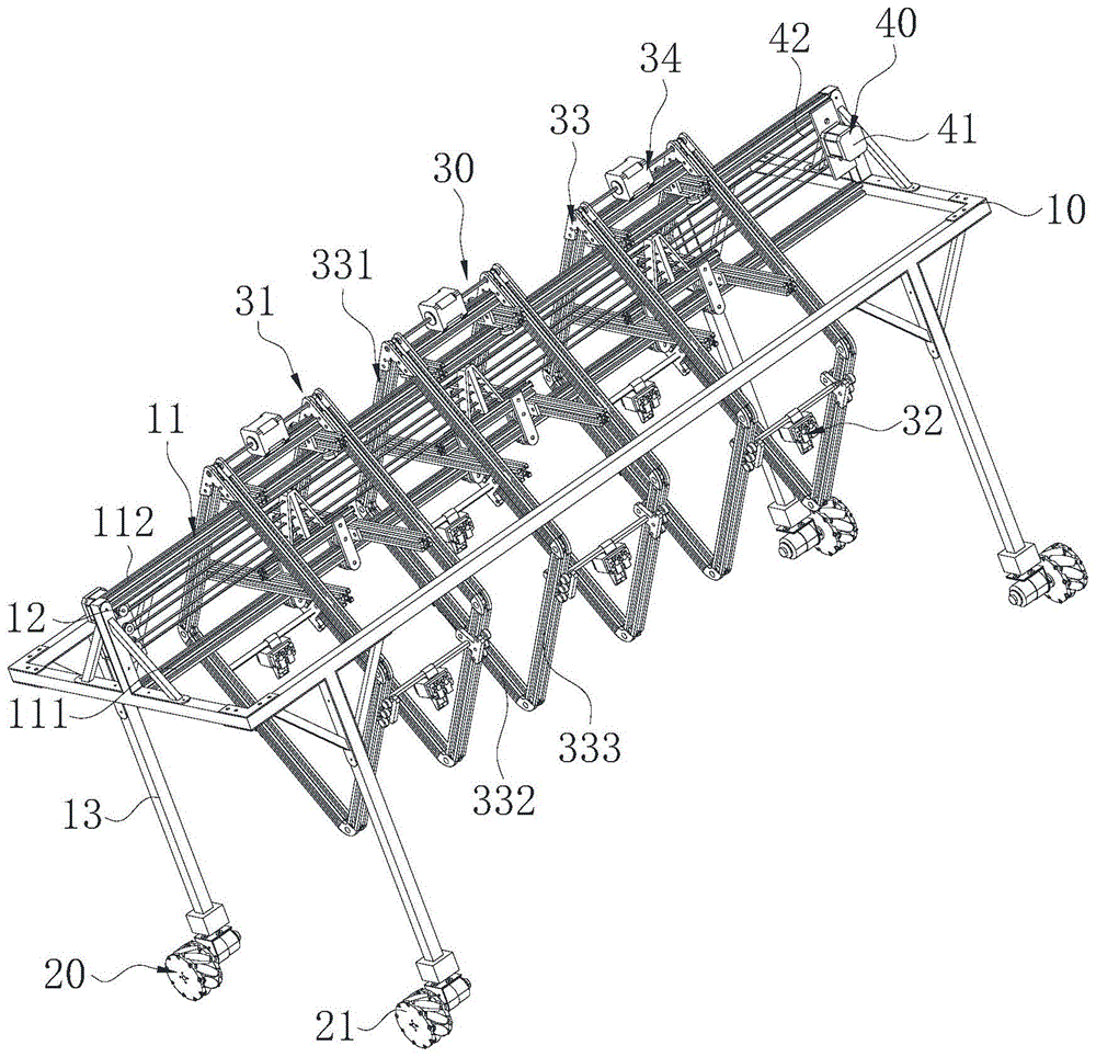
embodiment 1 of the present invention provides a wharf hoisting and transporting vehicle, including a vehicle frame 10, a traveling unit 20, a control unit (not shown), and at least one hoisting unit 30, wherein a mounting frame 11 is fixed on the vehicle frame 10; the walking unit 20 is mounted on the frame 10 and used for driving the frame 10 to move along the ground; the hoisting unit 30 is mounted on the mounting frame 11, the hoisting unit is provided with a lifting device 31 and at least one clamping device 32, the lifting device 31 is used for driving each clamping device 32 to lift so as to move each clamping device 32 to the goods; the control unit is electrically connected with the walking unit 20, the lifting device 31 and the clamping device 32, and is used for controlling the walking unit 20, the lifting device 31 and the clamping device 32, so that the clamping unit clamps the goods, and the walking unit 20 drives the frame 10 to move along the ground to transport the goods.
Specifically, by arranging the frame 10, the walking unit 20, the hoisting unit 30 and the control unit, the hoisting unit 30 is provided with the lifting device 31 and the clamping device 32, and when the lifting device works, the control unit controls the walking unit 20 to drive the frame 10, so that the frame 10 moves to a goods stacking position along a specified line; after the frame 10 moves to the goods stacking position, the control unit controls the lifting device 31 to drive each clamping device 32, so that each clamping device 32 moves to the goods position through lifting; the control unit controls the clamping device 32 which moves to the goods to clamp the goods through opening and closing; after the clamping device 32 clamps the goods, the control unit controls the traveling unit 20 to start, so that the traveling unit 20 drives the frame 10 to move to the wharf working area along a specified line; the control unit controls the lifting device 31 and the gripping device 32 again to deposit the goods in the working area of the quay; through above working method, can make the transport of goods to the whole journey of pier only through the floor truck execution, can effectively alleviate the manpower and materials of cargo handling process, reduce the handling cost of goods.
It is understood that the vehicle frame 10 is any frame structure capable of walking on the ground, and the vehicle frame 10 of the present embodiment has a vehicle body and four legs 13 vertically fixed on the vehicle body.
It can be understood that the walking unit 20 can be configured as a combination of a stepping motor and at least one walking wheel 26, each walking wheel 26 is rotatably connected to the supporting leg 13, and the driving of each walking wheel 26 by the stepping motor realizes the driving of the frame 10; or a plurality of stepping motors and a plurality of walking wheels 26 can be arranged, and the walking wheels 26 are driven separately by the stepping motors, so that the frame 10 is driven.
In order to facilitate accurate driving of the position of the vehicle frame 10, in the present embodiment, four traveling devices 21 are respectively disposed on the four legs 13, each of the four traveling devices 21 is provided with a stepping motor and a walking path, and the vehicle frame 10 is driven by the four traveling devices 21.
In this embodiment, the number of hoisting units 30 is 3, can make the floor truck once accessible 3 hoisting units 30 of group transport 3 groups of goods, effectively promote floor truck's conveying efficiency.
It will be appreciated that the lifting unit 30 may be mounted on the frame 10 by sliding or fixing, and in this embodiment, to facilitate the lifting of the goods by the lifting unit 30, the lifting unit 30 is slidably connected to the frame 10 to achieve precise adjustment of the position of the lifting unit 30.
It can be understood that the lifting device 31 can be a combination of a motor and a screw rod, the clamping device 32 is arranged on the screw rod sleeve of the screw rod, and the lifting of the clamping device 32 is realized, or a combination of a motor and a belt is arranged, the clamping device 32 is fixed on the belt, and the belt is driven to rotate by the motor, so that the lifting of the clamping device 32 is realized.
It can be understood that the clamping device 32 can be any structure with a clamping function, such as a clamping cylinder, a steering engine and the like, so as to control the clamping mechanism conveniently.
In this embodiment, the control unit controls the traveling unit 20 to drive the carriage 10 to travel along the tracking belt.
Preferably, the lifting device 31 includes a hoisting frame 33 and a driving assembly 34, the hoisting frame 33 includes a mounting end 331, a first lifting rail 332 and a second lifting rail 333, the mounting end 331 is mounted on the mounting frame 11, the upper ends of the first lifting rail 332 and the second lifting rail 333 are fixed to the mounting end 331, the number of the clamping devices 32 is at least two, each clamping device 32 is slidably connected to the first lifting rail 332 and the second lifting rail 333, and the driving assembly 34 is configured to drive each clamping device 32 to slide along the surface of the first lifting rail 332 and the surface of the second lifting rail 333, so as to lift each clamping device 32, and the lifting directions of the clamping devices 32 on the first lifting rail 332 and the clamping devices 32 on the second lifting rail 333 are opposite.
Specifically, the driving assembly 34 drives the clamping device 32 to slide along the surfaces of the first lifting rail 332 and the second lifting rail 333 under the control of the control unit, so as to lift the clamping device 32, and the clamping device 32 on the second lifting rail 333 is lifted while the clamping device 32 on the first lifting rail 332 is lowered, or the clamping device 32 on the second lifting rail 333 is lowered while the clamping device 32 on the first lifting rail 332 is lifted. Through the arrangement, the hoisting unit 30 can realize hoisting of a plurality of goods at a time, and the carrying efficiency of the carrying trolley is effectively improved.
It is understood that mounting end 331 may be any structure that may be implemented in frame 10, such as a plate, a frame, etc.
It can be understood that the first lifting rail 332 and the second lifting rail 333 may extend toward a direction close to the walking unit 20 or a direction away from the walking unit 20, the height of the lowest point of the first lifting rail 332 and the second lifting rail 333 is lower than the height of the highest point thereof, the first lifting rail 332 and the second lifting rail 333 may be curved or linear, the first lifting rail 332 and the second lifting rail 333 may be located on the same side of the mounting block 11 or on two sides of the mounting block 11, and the number of the first lifting rail 332 and the second lifting rail 333 may be multiple.
In this embodiment, the number of the clamping devices 32 of each hoisting unit 30 is 2, and the two clamping devices 32 are respectively mounted on the first lifting rail 332 and the second lifting rail 333, and since the number of the hoisting units 30 is 3, the transportation cart can form 6 clamping devices 32, and meanwhile, transportation of 6 pieces of goods is realized.
Preferably, the first lifting rail 332 and the second lifting rail 333 are respectively located at two sides of the mounting frame 11, and a lower end of the first lifting rail 332 and a lower end of the second lifting rail 333 are fixedly connected. Specifically, the first lifting rail 332 and the second lifting rail 333 are respectively located on two sides of the mounting frame 11, so that the stress of the mounting frame 11 can be effectively balanced, the lower end of the first lifting rail 332 and the lower end of the second lifting rail 333 are fixedly connected to stabilize the structure of the hoisting frame 33, when the second lifting rail 333 of the first lifting rail 332 is arc-shaped, the second lifting rail 333 of the first lifting rail 332 is enclosed to form a semicircular structure, and when the second lifting rail 333 of the first lifting rail 332 is linear, the second lifting rail 333 of the first lifting rail 332 is enclosed to form a V-shaped structure.
In this embodiment, to stabilize the structure of hoisting frame 33, second lifting rail 333 of first lifting rail 332 is preferably a linear rail.
In this embodiment, in order to facilitate the installation of the holding device 32 and the mechanism for stabilizing the hoisting frame 33, the number of the first lifting rail 332 and the second lifting rail 333 is two, the two first lifting rails 332 are disposed at intervals, and the two second lifting rails 333 are disposed at intervals.
Preferably, the driving assembly 34 includes a dual-axis motor 311 and an elevating belt 312, the dual-axis motor 311 is fixed on the mounting end 331 and electrically connected to the control unit, the mounting end 331 is fixed with an elevating driving wheel 334, the elevating driving wheel 334 is fixed on a shaft of the dual-axis motor 311, the elevating belt 312 is sleeved on the surfaces of the elevating driving wheel 334, the first elevating rail 332 and the second elevating rail 333, each of the clamping devices 32 is clamped on the elevating belt 312, and the control unit is configured to control the start and stop of the dual-axis motor 311.
Specifically, after the frame 10 moves to the cargo stacking position along the trajectory, the control unit controls the dual-shaft motor 311 to start and drive the lifting transmission wheel 334 to rotate, when the lifting transmission wheel 334 rotates, the lifting belt 312 is driven to rotate around the mounting end 331, the first lifting rail 332 and the second lifting rail 333, and when the lifting belt 312 rotates, the clamping device 32 is driven to slide on the surfaces of the first lifting rail 332 and the second lifting rail 333, so as to achieve the lifting of the clamping device 32.
In this embodiment, the lifting belt 312 is provided with two, the mounting end 331 is fixed with two lifting transmission wheels 334, the two lifting belts 312 are respectively sleeved on the two lifting transmission wheels 334, the two first lifting rails 332 and the two second lifting rails 333, the clamping device 32 is clamped on the two lifting belts 312, the dual-shaft motor 311 is a two-shaft driving motor, when the dual-shaft motor 311 is started, the dual-shaft motor 311 drives two shafts to rotate simultaneously, and finally drives the rotation of the two lifting belts 312. Stable lifting of the holding device 32 is achieved.
In this embodiment, the dual-shaft motor 311 is a stepping motor with a model number of 42BYJH47, a rated voltage of the stepping motor is 12-24V, a stepping angle of the stepping motor is 1.8 °, a torque of the stepping motor is 0.55n.m, the number of the dual-shaft motors 311 is 3, and the 3 dual-shaft motors 311 are respectively installed on the 3 lifting units.
Preferably, the clamping devices 32 comprise steering gears 321 and lifting frames 322, wherein one ends of the lifting frames 322 are provided with clamping protrusions 323 and two clamping limiting wheels 324 which are arranged oppositely, the clamping protrusions 323 are clamped with the lifting belts 312, the two clamping limiting wheels 324 are respectively connected to two sides of the first lifting rail 332 and two sides of the second lifting rail 333 in a rolling manner, the steering gears 321 are fixed on the lifting frames 322 and are electrically connected with the control unit, the steering gears 321 are fixedly provided with clamping jaws 325, and the control unit is used for controlling the steering gears 321 to enable the steering gears 321 to drive the clamping jaws 325 to open and close.
Specifically, the crane 322 is fixed on the surfaces of the first lifting rail 332 and the second lifting rail 333 through the clamping effect of the two clamping limiting wheels 324, the clamping protrusion 323 at the end part of the crane 322 is clamped on the lifting belt 312, so that when the lifting belt 312 rotates, the crane 322 is driven to slide along the surfaces of the first lifting rail 332 and the second lifting rail 333 through the clamping protrusion 323 at the clamping end part of the crane 322, meanwhile, the two clamping limiting wheels 324 are driven to roll along the surfaces of the first lifting rail 332 and the second lifting rail 333, the stable lifting of the steering engine 321 is finally realized, the clamping jaw 325 is fixed on the steering engine 321, and the clamping jaw 325 clamps the goods through opening and closing.
In this embodiment, the two ends of the lifting frame 322 are respectively provided with a clamping protrusion 323 and two clamping limiting wheels 324 arranged oppositely, so as to realize the installation of the lifting frame 322 on the second lifting rail 333 of the two first lifting rails 332.
In this embodiment, two auxiliary wheels 326 are disposed at two ends of the lifting frame 322, the two auxiliary wheels 326 are disposed at two sides of one of the clamping limiting wheels 324, and the two auxiliary wheels 326 can keep stable connection between the clamping device 32 and the first lifting rail 332 and the second lifting rail 333 when the transportation cart is bent.
In this embodiment, the surface of the cargo is provided with a handle for clamping, and the clamping jaw 325 clamps the cargo through the clamping handle.
In the embodiment, the steering engine 321 is ES08MA, the rated voltage is 4.8-6.0V, and the torque is 1.5 kg.cm.
Preferably, the vehicle body further comprises an adjusting unit 40, the adjusting unit 40 is fixed on the vehicle frame and electrically connected with the control unit, the mounting frame comprises a first adjusting rail 111 and a second adjusting rail 112 which are parallel to each other, the first adjusting rail 111 and the second adjusting rail 112 are both horizontally fixed on the vehicle frame, the second adjusting rail 112 is located above the first adjusting rail 111, the mounting end 331 is provided with a first limiting frame 35 and a second limiting frame 36, the first limiting frame 35 is slidably connected on the first adjusting rail 111, the upper and lower sides of the mounting end 331 are limited by the first adjusting rail 111, the second limiting frame 36 is slidably connected to the second adjusting rail 112, and the left and right sides of the mounting end 331 are limited by the second adjusting rail 112, and the adjusting unit 40 is used for driving the first limiting frame 35 and the second limiting frame 36 to slide along the first adjusting rail 111 and the second adjusting rail 112 respectively under the control of the control unit.
Specifically, since the vehicle frame 10 moves along the trajectory, when the vehicle frame 10 moves to the unloading position, the clamping device 32 may still have a certain deviation from the unloading position of the cargo, and at this time, the control unit may control the adjusting unit 40 to drive the lifting unit 30 to slide along the first adjusting rail 111, so that the cargo is accurately located at the unloading position.
In this embodiment, since the number of the hoisting units 30 is set to 3 groups, when the transportation cart hoists, due to the limitation of the length of the frame 10, it is impossible to hoist the goods by the 3 groups of hoisting units 30 simultaneously, and only after one group of hoisting units 30 complete hoisting, another goods can be hoisted by the adjacent hoisting unit, in order to avoid the interference of the adjacent hoisting units 30 on hoisting of the goods due to too close distance, therefore, when one hoisting unit 30 hoists, the two adjacent hoisting units 30 can be driven to be away from each other by the adjusting unit 40, when unloading, the goods of the 3 groups of hoisting units 30 are unloaded simultaneously, and in order to ensure that the goods are properly kept specific, after the adjusting unit 40 adjusts the distance between the 3 groups of hoisting units 30, the goods are unloaded by the 3 groups of hoisting units 30.
Preferably, the first limiting frame 35 includes a first fixed beam 351 and at least one first sliding frame 352 including two first adjusting limiting wheels 353 and two mounting plates 354, the two mounting plates 354 are oppositely disposed and vertically fixed on the first fixed beam 351, the two first adjusting limiting wheels 353 are rotatably connected between the two mounting plates 354, a limiting cavity 355 is formed between the two first adjusting limiting wheels 353 and the two mounting plates 354, the first adjusting rail 111 is located in the limiting cavity 355, the first adjusting limiting wheels 353 are located at the upper and lower sides of the first adjusting rail 111, the other side of the first fixed beam 351 is fixed with a connecting frame 357, and the adjusting unit 40 is in driving connection with the connecting frame 357.
Specifically, the two first adjustment limiting wheels 353 are arranged to realize the sliding of the mounting end 331 on the first adjustment rail 111, and the limiting cavity 355 enables the sliding of the mounting end 331 on the first adjustment rail 111 to be more stable.
In this embodiment, the number of the first carriages 352 is two.
Optionally, the first sliding frame 352 further includes two fixing plates 356, and the two fixing plates 356 are respectively fixed on the two mounting plates 354 and are fixedly connected to the mounting ends 331. In particular, fixed plate 356 may stabilize the connection of first sliding frame 352 to mounting end 331, making the sliding movement of lifting frame 33 along first adjustment rail 111 and second adjustment rail 112 more stable. In this embodiment, the adjusting unit 40 includes an adjusting motor 41 and an adjusting belt 42, the model of the adjusting motor 41 is a stepping motor of 42BYJH47, the rated voltage of the stepping motor is 12-24V, the stepping angle is 1.8 °, the torque is 0.55n.m, the number of the adjusting motors 41 is 3, the adjusting motor 41 is fixed at one end of the mounting frame 11, the other end of the mounting frame 11 is fixed with an adjusting rotating wheel 12, the adjusting belt 42 is sleeved on the crankshaft of the adjusting motor 41 and the adjusting rotating wheel 12, and the connecting frame 357 is fixed on the adjusting belt 42.
Preferably, the mounting frame 11 further includes a second adjusting rail 112, the second adjusting rail 112 is horizontally erected on the frame 10 and is parallel to the first adjusting rail 111, the second limiting frame 36 includes a second fixing beam 361 and at least one second sliding frame 362, the second fixing beam 361 is horizontally fixed on the mounting end 331 and is located on one side of the second adjusting rail 112, each second sliding frame 362 includes a wheel frame 363 and two second adjusting limiting wheels 364, the wheel frame 363 is fixed on the second fixing beam 361, and the two second adjusting limiting wheels 364 are rotatably connected to the wheel frame 363 and are respectively located on the left and right sides of the second adjusting rail 112. Specifically, the sliding of the lifting unit on the mounting frame 11 can be effectively stabilized by the limiting of the second adjusting limiting wheel 364.
In this embodiment, the number of the second carriages 362 is two.
In this embodiment, the mounting end 331 includes two V-shaped frames 335, the V-shaped frame 335 includes two supports, a first connecting beam 336 and a second connecting beam 337, the two supports are disposed at an included angle, the connecting position of the two supports forms the tip of the V-shaped frame 335, the tip of the V-shaped frame is located above the second adjusting rail, the two supports of the V-shaped frame 335 are respectively located at two sides of the mounting frame 11, the first connecting beam 336 and the second connecting beam 337 are both horizontally fixed on the two supports on the V-shaped frame 335, the first fixing beam 351 and the second fixing beam 361 are both horizontally erected between the two V-shaped frames 335, both ends of the first fixing beam 351 are respectively fixed on the first connecting beam 336 of the two V-shaped frames 335, the second fixing beam 361 is fixed on the second connecting beam 337 of the two V-shaped frames 335, the two first lifting rails 332 are fixed on the end of one of the two V-shaped frames 335, the upper ends of the two second lifting rails 333 are fixed on the end of the other support of the two V-shaped frames 335, the first lifting rail 332, the second lifting rail 333 and the V-shaped frame 335 enclose to form a diamond structure.
Specifically, the V-shaped frame 335, the first lifting rail 332 and the second lifting rail 333 are enclosed to form a rhombic frame structure, the hoisting frame is provided with two rhombic frames, the two rhombic frames are connected through the first fixing beam 351 and the second fixing beam 361, and the lifting belt 312 is sleeved on the surfaces of the lifting transmission wheel, the V-shaped frame 335, the first lifting rail 332 and the second lifting rail 333. By this arrangement, hoisting frame 33 can be made to slide stably along the first and second adjustment rails while keeping hoisting frame 33 itself structurally stable.
Preferably, the traveling unit 20 includes a plurality of traveling devices 21, each of the plurality of traveling devices 21 includes a limiting shell 22, a damping spring 23, a damping chassis 24, a traveling motor 25 and a traveling wheel 26, each of the limiting shells 22 is fixed to the lower end of the vehicle frame 10, the damping chassis 24 is located below the limiting shell 22 and is slidably connected to the limiting shell 22, the damping spring 23 is located between the damping chassis 24 and the limiting shell 22, two ends of the damping spring 23 respectively abut against the damping chassis 24 and the limiting shell 22, the traveling motor 25 is fixed to the damping chassis 24 and is electrically connected to the control unit, and the traveling wheel 26 is fixed to a crankshaft of the traveling motor 25.
Specifically, the control unit controls the running motor to start and stop, the running motor drives the running wheels 26 to rotate when being started, the movement of the frame 10 is realized, and the shock absorption of the frame 10 can be realized through the shock absorption springs 23 when the frame 10 runs.
In the present embodiment, the traveling motor 25 is a reduction motor of type M2006P36, and has a rated voltage of 24V, a reduction ratio of 1:36, and a torque of 1.0 n.m.
In this embodiment, the traveling wheels 26 are mecanum wheels having a self-rotating characteristic, so as to turn the frame 10, and the angle can be finely adjusted, so as to adjust the line of the frame 10.
In this embodiment, the control unit includes a control IC, and a cargo identifier, a speed regulator, a two-way driver, a driving board, a cruise sensor, and a gyroscope electrically connected to the control IC, and the control IC, the cargo identifier, the speed regulator, the two-way driver, the driving board, the cruise sensor, and the gyroscope are all fixed to the frame 10.
In this embodiment, the cruise sensors and the gyroscopes are four groups, and the four groups of cruise sensors and gyroscopes are respectively fixed on the support legs 13 of the frame 10 and are located on one side of the road wheels 26. The model of each cruise sensor is HJ-XJ 4's four ways tracking module, its operating voltage is 5V, the detection distance is 15-25mm, there are 4 grey level response receivers and grey level response transmitter on each four ways tracking module, when the receiver monitors the colour (black) that the grey level is great, the output level changes from the high low, the LED lamp that corresponds is bright, then when two cruise sensors of same side leg are all on the tracking area, the LED lamp of homonymy is bright, can guarantee that the hoist does not deviate from the tracking area. The gyroscope is an MPU-6050 acceleration angle sensor, the model is JY61, the working voltage is 5V, and the resolution is 0.61 DEG/s. When the whole vehicle moves, the tracking module and the gyroscope are mainly used for sensing the position and the deflection angle of the whole vehicle. The width of the tracking belt is 30mm, and when the crane gyroscope senses that the traveling wheels 26 deviate from the tracking belt, the control unit drives the traveling unit 20 to automatically correct the offset.
The distance between two gray level sensors in the middle of the four-way tracking module is 16 mm. Because the body of the carrying trolley is longer, the tracking sensor is arranged behind the front body of the carrying trolley, so that the situation that one end of the carrying trolley is positioned on the tracking line and the other end of the carrying trolley deviates out of the tracking line can be avoided. The frequency of the signals of the two tracking modules is once 2ms, and the maximum moving speed of the carrying trolley in the process of grabbing the goods is 0.314 mm/ms. Assuming that the maximum deviation angle of the cart is 30 degrees under the worst condition, namely the motion error caused by uneven friction force of wheels is 30 degrees, the maximum error of the cart frame 10 in the direction perpendicular to the tracking belt is 7.363mm <40mm in the motion process, and the cart frame 10 does not deviate from the tracking belt.
In this embodiment, the goods recognizer is the microcomputer raspberry group based on Linux system, and the raspberry group is fixed in the middle part of frame 10, is provided with the camera on the raspberry group, and the camera can discern the colour and the shape of goods to the point of grabbing of discernment goods, and send the point of grabbing of goods to transmit for drive IC through the raspberry, in order to make things convenient for drive IC to elevating gear 31 and clamping device 32's control.
In this embodiment, the model of the speed governor is C610, the number of the speed governors is 4, and the 4 speed governors respectively control the start and stop of the 4 traveling motors 25 and the rotation speed of the traveling motors 25.
In this embodiment, the model of double-circuit driver is a4988, and the quantity of double-circuit driver is 3, 3 double-circuit drivers, and one of them of 3 double-circuit drivers is connected with 3 double-shaft motor 311 respectively, and 3 other branches of double-circuit driver are connected with 3 accommodate motor 41 respectively to realize control IC to accommodate motor 41 and double-shaft motor 311's control.
In this embodiment, the number of the drive plates is 6, and 6 drive plates are fixed to 6 steering engines 321 respectively to be used for controlling the start and stop of 6 steering engines 321.
In this embodiment, control IC is STM32F103VET6 main control board, and it has 100 GPIO mouths, and the gyroscope is connected with 1 UART interface (4 GPIO mouths wherein), and the line sensor is patrolled in the four ways is connected with 24 GPIO mouths wherein, and the drive plate is connected with 6 GPIO mouths wherein, and the double-circuit driver is connected with 24 GPIO mouths wherein, and the speed regulator is connected with 24 GPIO mouths wherein.
Example 2:
the embodiment 2 of the invention provides a carrying method of a wharf hoisting truck, which comprises the following steps:
s100: the control unit controls the traveling unit 20 to drive the vehicle frame 10 so that the vehicle frame 10 moves to a cargo stacking position along a designated line;
s200: the control unit controls the lifting device 31 to drive each clamping device 32, so that each clamping device 32 moves to the goods through lifting;
s300: the control unit controls the clamping device 32 to enable the clamping device 32 moving to the goods to clamp the goods through opening and closing;
s400: the control unit controls the running unit 20 to start, so that the running unit 20 drives the vehicle frame 10 to move to a wharf working area along a specified line;
s500: the control unit stacks the goods in the working area of the quay by controlling the lifting device 31 and the clamping device 32 again.
Particularly, through the above working mode of the carrying trolley, the whole process from carrying of the goods to the wharf is only carried out through the carrying trolley, manpower and material resources in the goods carrying process can be effectively reduced, and the carrying cost of the goods is reduced.
After each clamping device 32 clamps the goods, the control unit controls the lifting device 31 to start, so that the lifting device 31 drives each clamping device 32 to lift, and the goods are kept flush;
the control unit controls the lifting device 31 to start, so that the lifting device 31 drives each clamping device 32, and the lifting control unit controls the clamping devices 32 to open, so that the goods are stacked in the working area of the wharf.
In this embodiment, in step S300, the control unit controls one of the lifting units 30 to operate, so that the lifting device 31 of the lifting unit 30 drives the clamping device 32 on the first lifting rail 332 to ascend, and at the same time, the clamping device 32 on the second lifting rail 333 descends, and after the clamping device 32 on the second lifting rail 333 descends to a certain height, the control unit controls the clamping device 32 to clamp the cargo. Then, the control unit controls the clamping device 32 on the second lifting rail 333 to ascend, at the same time, the clamping device 32 on the first lifting rail 332 descends, after the clamping device 32 on the first lifting rail 332 descends to a certain height, the control unit controls the clamping device 32 to clamp the goods, and finally, the control unit controls the two clamping devices 32 of the hoisting unit 30 to ascend or descend, so that the two clamped goods are on the same horizontal plane.
After the lifting of the goods by the lifting unit 30 is completed, the carriage 10 is moved, and the lifting of another lifting unit 30 is completed by the same method until the lifting of 3 groups of lifting units 30 is completed.
In step S500, the control unit controls 3 gripping devices 32 of the first lifting rail 332 or the second lifting rail 333 on the 3 groups of hoisting units 30 to simultaneously lower, so as to simultaneously unload the goods on the 3 gripping devices 32, and controls the other 3 gripping devices 32 to simultaneously lower, so as to simultaneously unload the other goods, and finally complete the unloading of the transportation cart.
The above-described embodiments of the present invention should not be construed as limiting the scope of the present invention. Any other corresponding changes and modifications made according to the technical idea of the present invention should be included in the protection scope of the claims of the present invention.