CN114483446A - Wind direction following rotation device of household wind driven generator - Google Patents
Wind direction following rotation device of household wind driven generator Download PDFInfo
- Publication number
- CN114483446A CN114483446A CN202111535437.1A CN202111535437A CN114483446A CN 114483446 A CN114483446 A CN 114483446A CN 202111535437 A CN202111535437 A CN 202111535437A CN 114483446 A CN114483446 A CN 114483446A
- Authority
- CN
- China
- Prior art keywords
- support frame
- outside
- wind
- block
- fixedly connected
- Prior art date
- Legal status (The legal status is an assumption and is not a legal conclusion. Google has not performed a legal analysis and makes no representation as to the accuracy of the status listed.)
- Withdrawn
Links
- 230000006698 induction Effects 0.000 claims abstract description 21
- XEEYBQQBJWHFJM-UHFFFAOYSA-N Iron Chemical compound [Fe] XEEYBQQBJWHFJM-UHFFFAOYSA-N 0.000 claims description 36
- 229910052742 iron Inorganic materials 0.000 claims description 18
- 244000309464 bull Species 0.000 claims description 9
- 238000010248 power generation Methods 0.000 claims description 8
- 230000004044 response Effects 0.000 claims description 5
- 230000000712 assembly Effects 0.000 claims description 4
- 238000000429 assembly Methods 0.000 claims description 4
- 230000008859 change Effects 0.000 abstract description 3
- 230000009471 action Effects 0.000 description 3
- 238000006243 chemical reaction Methods 0.000 description 2
- 230000004075 alteration Effects 0.000 description 1
- 230000009286 beneficial effect Effects 0.000 description 1
- 230000000903 blocking effect Effects 0.000 description 1
- 239000003245 coal Substances 0.000 description 1
- 230000007547 defect Effects 0.000 description 1
- 230000000694 effects Effects 0.000 description 1
- 230000005611 electricity Effects 0.000 description 1
- 238000001125 extrusion Methods 0.000 description 1
- 230000001939 inductive effect Effects 0.000 description 1
- 230000004048 modification Effects 0.000 description 1
- 238000012986 modification Methods 0.000 description 1
- 230000035945 sensitivity Effects 0.000 description 1
- 238000000926 separation method Methods 0.000 description 1
- 238000006467 substitution reaction Methods 0.000 description 1
Images



Classifications
-
- F—MECHANICAL ENGINEERING; LIGHTING; HEATING; WEAPONS; BLASTING
- F03—MACHINES OR ENGINES FOR LIQUIDS; WIND, SPRING, OR WEIGHT MOTORS; PRODUCING MECHANICAL POWER OR A REACTIVE PROPULSIVE THRUST, NOT OTHERWISE PROVIDED FOR
- F03D—WIND MOTORS
- F03D7/00—Controlling wind motors
- F03D7/02—Controlling wind motors the wind motors having rotation axis substantially parallel to the air flow entering the rotor
- F03D7/0204—Controlling wind motors the wind motors having rotation axis substantially parallel to the air flow entering the rotor for orientation in relation to wind direction
-
- Y—GENERAL TAGGING OF NEW TECHNOLOGICAL DEVELOPMENTS; GENERAL TAGGING OF CROSS-SECTIONAL TECHNOLOGIES SPANNING OVER SEVERAL SECTIONS OF THE IPC; TECHNICAL SUBJECTS COVERED BY FORMER USPC CROSS-REFERENCE ART COLLECTIONS [XRACs] AND DIGESTS
- Y02—TECHNOLOGIES OR APPLICATIONS FOR MITIGATION OR ADAPTATION AGAINST CLIMATE CHANGE
- Y02B—CLIMATE CHANGE MITIGATION TECHNOLOGIES RELATED TO BUILDINGS, e.g. HOUSING, HOUSE APPLIANCES OR RELATED END-USER APPLICATIONS
- Y02B10/00—Integration of renewable energy sources in buildings
- Y02B10/30—Wind power
-
- Y—GENERAL TAGGING OF NEW TECHNOLOGICAL DEVELOPMENTS; GENERAL TAGGING OF CROSS-SECTIONAL TECHNOLOGIES SPANNING OVER SEVERAL SECTIONS OF THE IPC; TECHNICAL SUBJECTS COVERED BY FORMER USPC CROSS-REFERENCE ART COLLECTIONS [XRACs] AND DIGESTS
- Y02—TECHNOLOGIES OR APPLICATIONS FOR MITIGATION OR ADAPTATION AGAINST CLIMATE CHANGE
- Y02E—REDUCTION OF GREENHOUSE GAS [GHG] EMISSIONS, RELATED TO ENERGY GENERATION, TRANSMISSION OR DISTRIBUTION
- Y02E10/00—Energy generation through renewable energy sources
- Y02E10/70—Wind energy
- Y02E10/72—Wind turbines with rotation axis in wind direction
Landscapes
- Engineering & Computer Science (AREA)
- Life Sciences & Earth Sciences (AREA)
- Sustainable Development (AREA)
- Sustainable Energy (AREA)
- Chemical & Material Sciences (AREA)
- Combustion & Propulsion (AREA)
- Mechanical Engineering (AREA)
- General Engineering & Computer Science (AREA)
- Wind Motors (AREA)
Abstract
The invention relates to the technical field of wind generators and discloses a household wind generator rotation device along with wind direction, which comprises a first support frame, wherein the outside of the first support frame is connected with a wind deflector for guiding and concentrating the wind direction, the inside of the first support frame is connected with an induction trigger device for controlling the device to start according to the direction and the size of the wind, the outside of the first support frame is connected with a second support frame for supporting a wind generator main body, the inside of the first support frame is connected with a clamping and starting device for controlling the rotation of the second support frame, the inside of the first support frame is connected with a positioning clamping point device for controlling the rotation angle of the second support frame, the inside of the first support frame is connected with a power supply for providing current for the clamping and starting device, the wind direction is changed through the wind deflector, the influence of wind on other induction trigger devices is reduced, the arrangement of a plurality of positioning clamping point devices can effectively improve the change of the wind direction, the accuracy of the angle change of the device can better improve the utilization efficiency of wind energy.
Description
Technical Field
The invention relates to the technical field of wind-driven generators, in particular to a wind-driven rotation device of a household wind-driven generator.
Background
The wind energy is a new energy with great potential, the wind power resource which can be used for generating electricity on the earth is about one hundred billion kilowatts and is almost ten times of the hydraulic power generation quantity all over the world, and the energy obtained by burning coal all over the world is only one third of the energy provided by wind power in one year.
Therefore, the utilization of clean new energy such as wind power, solar energy and the like is more and more emphasized in all countries in the world, but different from solar energy, the solar energy can be utilized more or less as long as the sunlight is kept on the ground, the light energy utilization rate is not changed greatly, and during wind power generation, once the wind direction of wind with the same wind speed is changed, the influence on the electric energy conversion efficiency is great, so that most of common household clean energy is solar energy, and less wind energy is selected for power generation.
Therefore, a wind power generator weathervane is needed to solve this problem.
Disclosure of Invention
Aiming at the defects of the prior art, the invention provides a wind-following rotation device of a household wind-driven generator, which has the advantages of automatic steering along the wind direction and fixed-point automatic stop, and solves the problem that the wind direction of wind with the same wind speed greatly influences the electric energy conversion efficiency once the wind direction is changed during wind power generation.
In order to realize the purposes of automatic wind direction steering and fixed-point automatic stop, the invention provides the following technical scheme: the utility model provides a domestic wind power generation machine rotation device along with wind direction, includes support frame one, the external connection of support frame one has the aviation baffle of dredging the concentration to the wind direction, the internal connection of support frame one has the response trigger device according to the direction of wind force and size and controlling means start, the external connection of support frame one has support frame two, the internal connection of support frame one has two pivoted screens of control support frame and starting drive, the internal connection of support frame one has two turned angle's of control support frame location stuck point device, the internal connection of support frame one provides the power of electric current for screens and starting drive.
Preferably, the induction triggering device comprises a first air bearing plate and a first conductive block, the first air bearing plate is connected to the outside of the first support frame in a sliding mode, a first connecting block is fixedly connected to the outside of the first air bearing plate, a first connecting rod is connected to the outside of the first connecting block in a rotating mode, a first sliding block is connected to the outside of the first connecting rod in a rotating mode, a second connecting rod is connected to the outside of the first sliding block in a rotating mode, a second connecting block is connected to the outside of the second connecting rod in a rotating mode, a first spring is fixedly connected to the outside of the second connecting block in a connecting mode, a second conductive block is fixedly connected to the outside of the first sliding block in a conducting mode, and the first conductive block is fixedly connected to the inside of the first support frame in a connecting mode.
Preferably, the first sliding block, the first connecting rod and the second connecting rod are symmetrically distributed on two sides of the first connecting block and the second connecting block, the first sliding block is connected inside the first supporting frame in a sliding mode, one end of the first spring is fixedly connected to the outside of the first connecting block, the other end of the first spring is fixedly connected to the outside of the second connecting block, and the first conducting block and the second conducting block are corresponding in position and matched in specification.
Preferably, screens and starting drive include motor, electro-magnet and cardboard one, and motor fixed connection is in the inside of support frame one, and the outside fixedly connected with bevel gear one of motor, bevel gear one's outside fixedly connected with bevel gear two, electro-magnet fixed connection is in the outside of support frame one, and cardboard one rotates the outside of connecting at support frame one, and the outside fixedly connected with spring two of cardboard one, the outside fixedly connected with cardboard two of spring two, the outside fixedly connected with iron plate one of cardboard two, the outside fixedly connected with iron plate two of cardboard one.
Preferably, the second clamping plate is rotatably connected to the outer portion of the first supporting frame, the second bevel gear is fixedly connected to the outer portion of the second supporting frame, the first iron block and the second iron block correspond to the electromagnet in position and are matched in specification, the first clamping plate corresponds to the first bevel gear in position and is matched in specification, and the second clamping plate corresponds to the second bevel gear in position and is matched in specification.
Preferably, the positioning and clamping point device comprises a third spring and a positioning assembly, one end of the third spring is fixedly connected inside the second support frame, the other end of the third spring is fixedly connected with a second sliding block, and the outer portion of the second sliding block is rotatably connected with a roller.
Preferably, the positioning assembly comprises a rotating rod and a third conducting block, the rotating rod is rotatably connected to the outside of the first support frame, a third connecting rod is rotatably connected to the outside of the rotating rod, a sliding plate is rotatably connected to the outside of the third connecting rod, a fourth spring is fixedly connected to the outside of the sliding plate, a fourth conducting block is fixedly connected to the outside of the sliding plate, a fourth connecting rod is movably connected to the inside of the rotating rod, and the three conducting blocks are fixedly connected to the inside of the first support frame.
Preferably, the position of conducting block three is corresponding with the position of conducting block four, and the one end fixed connection of spring four is in the outside of slide, and other end fixed connection is in the outside of support frame one, and two sliding connection of slider are in the inside of support frame two, and bull stick, connecting rod three respectively have two and symmetric distribution in the both sides of slide, and the spout has been seted up on the surface of bull stick, and the inside sliding connection of spout has connecting rod four, and positioning element quantity is no less than eight, and evenly distributed is in the inside of support frame one.
Preferably, the number of the induction triggering devices is not less than eight, the induction triggering devices correspond to the positions of the positioning assemblies, each induction triggering device and the corresponding positioning assembly form a relatively independent circuit branch, and each branch can independently control the power-on states of the motor and the electromagnet.
Preferably, the first conducting block is electrically connected with the third conducting block, the power supply, the electromagnet and the motor, the second conducting block is electrically connected with the fourth conducting block, the power supply, the electromagnet and the motor, the third conducting block is in contact with the fourth conducting block in an initial state, and at the moment, if the first conducting block is in contact with the second conducting block, a circuit is switched from an open circuit to a closed circuit, and the power supply is switched on and supplies power to the electromagnet and the motor.
Advantageous effects
Compared with the prior art, the invention provides a wind-following rotation device of a household wind-driven generator, which has the following beneficial effects:
1. this domestic wind power generation machine rotation device along with wind changes the wind direction through the aviation baffle, has improved the response sensitivity of response trigger device to wind-force on the one hand, and on the other hand has also reduced wind to other response trigger device's influence, and the setting of a plurality of location stuck point devices can effectively improve the wind direction and change the back, and the precision that the device angle changed can better improve the utilization efficiency of wind energy.
2. This domestic wind energy generator rotation device along with wind determines the degree of support frame two rotations through locating component, makes conducting block three and conducting block four separation through the contact of gyro wheel and the bull stick in certain locating component and extrusion, and then makes the circuit corresponding with this locating component become the broken circuit by the route, has realized the purpose of fixed point automatic stop.
Drawings
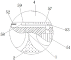
FIG. 1 is a sectional view of a portion of the present invention;
FIG. 2 is an enlarged view of the structure at A in FIG. 1;
FIG. 3 is a cross-sectional view of a portion of the structure of the present invention;
FIG. 4 is a schematic view of the structural connection between the inductive triggering device and the positioning stuck point device according to the present invention;
FIG. 5 is an enlarged view of the structure at B in FIG. 4;
in the figure: 1. a first support frame; 2. an air deflector; 3. an induction triggering device; 31. a wind-bearing plate; 32. a first conductive block; 33. a first connecting block; 34. a first connecting rod; 35. a first sliding block; 36. a second connecting rod; 37. a second connecting block; 38. a first spring; 39. a second conductive block; 4. a second support frame; 5. a clamping and starting device; 51. a motor; 52. an electromagnet; 53. a first clamping plate; 54. a first bevel gear; 55. a second bevel gear; 56. a second spring; 57. a second clamping plate; 58. a first iron block; 59. a second iron block; 6. positioning a stuck point device; 61. a third spring; 62. a positioning assembly; 621. a rotating rod; 622. a third conductive block; 623. a third connecting rod; 624. a slide plate; 625. a fourth spring; 626. a fourth conductive block; 627. a connecting rod IV; 63. a second sliding block; 64. a roller; 7. a power source.
Detailed Description
The technical solutions in the embodiments of the present invention will be clearly and completely described below with reference to the drawings in the embodiments of the present invention, and it is obvious that the described embodiments are only a part of the embodiments of the present invention, and not all of the embodiments. All other embodiments, which can be derived by a person skilled in the art from the embodiments given herein without making any creative effort, shall fall within the protection scope of the present invention.
The first embodiment is as follows:
referring to fig. 1, 3 and 4, a household wind driven generator rotation device along the wind direction comprises a support frame 1, a wind deflector 2 for guiding and concentrating the wind direction is connected to the outside of the support frame 1, an induction trigger device 3 for controlling the device to start according to the direction and the size of the wind is connected to the inside of the support frame 1, the induction trigger device 3 comprises a wind bearing plate 31 and a first conductive block 32, the wind bearing plate 31 is slidably connected to the outside of the support frame 1, a first connecting block 33 is fixedly connected to the outside of the wind bearing plate 31, a first connecting rod 34 is rotatably connected to the outside of the first connecting block 33, a first sliding block 35 is rotatably connected to the outside of the first connecting rod 34, the first sliding block 35 is slidably connected to the inside of the support frame 1, a second connecting rod 36 is rotatably connected to the outside of the first sliding block 35, a second connecting block 37 is rotatably connected to the outside of the second connecting rod 36, the first sliding block 35, the first connecting rod 34 and the second connecting rod 36 are symmetrically distributed on two sides of the first connecting block 33 and the second connecting block 37, the outside fixedly connected with spring 38 of connecting block two 37, the one end fixed connection of spring 38 is in the outside of connecting block one 33, other end fixed connection is in the outside of connecting block two 37, outside fixedly connected with conducting block two 39 of slider one 35, conducting block one 32 and the corresponding and specification phase-match in position of conducting block two 39, conducting block one 32 fixed connection is in the inside of support frame one 1, the external connection of support frame one 1 has support frame two 4, the internal connection of support frame one 1 has two 4 pivoted screens of control support frame and starting drive 5, the internal connection of support frame one 1 has two 4 turned angle's of control support frame location stuck point device 6, the internal connection of support frame one 1 provides the power 7 of electric current for screens and starting drive 5.
Example two:
referring to fig. 1, 3 and 5, a wind direction following rotation device of a household wind power generator comprises a support frame 1, a wind deflector 2 for guiding and concentrating wind direction is connected to the outside of the support frame 1, an induction trigger device 3 for controlling the start of the device according to the direction and the size of the wind direction is connected to the inside of the support frame 1, a support frame two 4 is connected to the outside of the support frame 1, a blocking and starting device 5 for controlling the rotation of the support frame two 4 is connected to the inside of the support frame 1, a positioning and clamping device 6 for controlling the rotation angle of the support frame two 4 is connected to the inside of the support frame 1, the positioning and clamping device 6 comprises a spring three 61 and a positioning assembly 62, the number of the positioning assemblies 62 is not less than eight, and the positioning assemblies 62 are uniformly dispersed in the inside of the support frame 1, the positioning assembly 62 comprises a rotating rod 621 and a conductive block three 622, the rotating rod 621 is rotatably connected to the outside of the support frame 1, a third connecting rod 623 is rotatably connected to the outer part of the rotating rod 621, a sliding plate 624 is rotatably connected to the outer part of the third connecting rod 623, two rotating rods 621 and two connecting rods 623 are respectively and symmetrically distributed on two sides of the sliding plate 624, a fourth spring 625 is fixedly connected to the outer part of the sliding plate 624, one end of the fourth spring 625 is fixedly connected to the outer part of the sliding plate 624, the other end of the fourth spring 625 is fixedly connected to the outer part of the first support frame 1, a fourth conductive block 626 is fixedly connected to the outer part of the sliding plate 624, the third conductive block 622 corresponds to the fourth conductive block 626 in position, a fourth connecting rod 627 is movably connected to the inner part of the rotating rod 621, a sliding groove is formed in the surface of the rotating rod 621, a fourth connecting rod 627 is slidably connected to the inner part of the sliding groove, the third conductive block 622 is fixedly connected to the inner part of the first support frame 1, one end of the third spring 61 is fixedly connected to the inner part of the second support frame 4, a second sliding block 63 is slidably connected to the inner part of the second support frame 4, the outside of the second sliding block 63 is rotatably connected with a roller 64, and the inside of the first supporting frame 1 is connected with a power supply 7 for supplying current to the clamping and starting device 5.
Example three:
referring to fig. 1-5, a household wind-driven generator rotation device along with wind direction comprises a support frame 1, a wind deflector 2 for guiding and concentrating wind direction is connected to the outside of the support frame 1, an induction trigger device 3 for controlling the device to start according to the direction and the size of the wind direction is connected to the inside of the support frame 1, the induction trigger device 3 comprises a wind bearing plate 31 and a first conductive block 32, the wind bearing plate 31 is slidably connected to the outside of the support frame 1, a first connecting block 33 is fixedly connected to the outside of the wind bearing plate 31, a first connecting rod 34 is rotatably connected to the outside of the first connecting block 33, a first sliding block 35 is rotatably connected to the outside of the first connecting rod 34, the first sliding block 35 is slidably connected to the inside of the support frame 1, a second connecting rod 36 is rotatably connected to the outside of the first sliding block 35, a second connecting block 37 is rotatably connected to the outside of the second connecting rod 36, two sliding blocks 35, the first connecting rod 34 and the second connecting rod 36 are symmetrically distributed on two sides of the first connecting block 33 and the second connecting block 37, the outer portion of the second connecting block 37 is fixedly connected with a first spring 38, one end of the first spring 38 is fixedly connected to the outer portion of the first connecting block 33, the other end of the first spring 38 is fixedly connected to the outer portion of the second connecting block 37, the outer portion of the first sliding block 35 is fixedly connected with a second conductive block 39, the first conductive block 32 corresponds to the second conductive block 39 in position and is matched in specification, the first conductive block 32 is fixedly connected to the inner portion of the first supporting frame 1, and the outer portion of the first supporting frame 1 is connected with a second supporting frame 4.
The inside of the support frame I1 is connected with a clamping and starting device 5 for controlling the rotation of the support frame II 4, the clamping and starting device 5 comprises a motor 51, an electromagnet 52 and a clamping plate I53, the motor 51 is fixedly connected inside the support frame I1, the outside of the motor 51 is fixedly connected with a bevel gear I54, the clamping plate I53 corresponds to the position of the bevel gear I54 and is matched with the specification, the outside of the bevel gear I54 is fixedly connected with a bevel gear II 55, the bevel gear II 55 is fixedly connected outside the support frame II 4, the electromagnet 52 is fixedly connected outside the support frame I1, the clamping plate I53 is rotatably connected outside the support frame I1, the outside of the clamping plate I53 is fixedly connected with a spring II 56, the outside of the spring II 56 is fixedly connected with a clamping plate II 57, the clamping plate II 57 is rotatably connected outside the support frame I1, the clamping plate II 57 is corresponding to the position of the bevel gear II 55 and is matched with the specification, the first iron block 58 is fixedly connected to the outer portion of the first clamping plate 57, the second iron block 59 is fixedly connected to the outer portion of the first clamping plate 53, and the first iron block 58 and the second iron block 59 correspond to the electromagnet 52 in position and are matched in specification.
The inside of the supporting frame 1 is connected with a positioning clamping point device 6 for controlling the rotation angle of the supporting frame two 4, the positioning clamping point device 6 comprises a spring III 61 and a positioning component 62, the number of the induction trigger devices 3 is not less than eight, the induction trigger devices 3 correspond to the positions of the positioning component 62, the number of the positioning component 62 is not less than eight, and the positioning component 62 is uniformly dispersed in the inside of the supporting frame 1, the positioning component 62 comprises a rotating rod 621 and a conductive block III 622, the rotating rod 621 is rotatably connected to the outside of the supporting frame 1, the outside of the rotating rod 621 is rotatably connected with a connecting rod III 623, the outside of the connecting rod III 623 is rotatably connected with a sliding plate 624, the rotating rod 621 and the connecting rod III 623 are respectively provided with two parts and are symmetrically distributed on two sides of the sliding plate 624, the outside of the sliding plate 624 is fixedly connected with a spring IV 625, one end of the spring IV 625 is fixedly connected to the outside of the sliding plate 624, and the other end is fixedly connected to the outside of the supporting frame 1, the outer part of the sliding plate 624 is fixedly connected with a conductive block IV 626, the conductive block III 622 corresponds to the position of the conductive block IV 626, the inner part of the rotating rod 621 is movably connected with a connecting rod IV 627, the surface of the rotating rod 621 is provided with a sliding groove, the inner part of the sliding groove is connected with the connecting rod IV 627 in a sliding way, the conductive block III 622 is fixedly connected with the inner part of the support frame I1, one end of the spring III 61 is fixedly connected with the inner part of the support frame II 4, the other end of the spring III is fixedly connected with the sliding block II 63, the sliding block II 63 is connected with the inner part of the support frame II 4 in a sliding way, the outer part of the sliding block II 63 is rotatably connected with a roller 64, the inner part of the support frame I1 is connected with a power supply 7 for providing current for the clamping and starting device 5, the conductive block I32 is electrically connected with the conductive block III 622, the power supply 7, the electromagnet 52 and the motor 51, the conductive block II 39 is electrically connected with the conductive block IV 626, the power supply 7, the electromagnet 52 and the motor 51, the conductive block IV 626 is electrically connected in an initial state, the conductive block III 622 is contacted with the conductive block IV 626, if the first conductive block 32 is in contact with the second conductive block 39, the circuit is switched from open circuit to open circuit, the power supply 7 is switched on and supplies power to the electromagnet 52 and the motor 51, each induction trigger device 3 and the corresponding positioning component 62 form a relatively independent circuit branch, and each branch can independently control the energization states of the motor 51 and the electromagnet 52.
The working principle is as follows: when the device is started, after a wind driven generator is installed, if the wind direction changes, a user can enable the wind bearing plate 31 in one induction triggering component 3 to be extruded by larger wind power under the action of the wind deflector 2, then the wind bearing plate 31 can slide, the wind bearing plate 31 can drive the connecting block I33 to slide, the connecting block I33 can slide to drive the connecting block I34 to rotate, the connecting block I34 can rotate to drive the sliding block I35 to slide, on one hand, the sliding block I35 can drive the connecting block II 36 to rotate, the connecting block II 36 can rotate to drive the connecting block II 37 to move, after the connecting block II 37 moves, the distance between the connecting block I33 is drawn to extrude the spring I38, on the other hand, the sliding block I35 can drive the conducting block II 39 to slide, so that the conducting block II 39 is in contact with the conducting block I32, when in an initial state, the conducting block III 622 is in contact with the conducting block IV, and a circuit branch corresponding to the induction triggering component 3 is changed from an open circuit to a channel, the power supply 7 is connected, the electromagnet 52 and the motor 51 are powered on, the electromagnet 52 is powered on to generate suction to the first iron block 58 and the second iron block 59, the first clamping plate 53 and the second clamping plate 57 which are fixedly connected with the first iron block 58 and the second iron block 59 respectively overcome the elastic force of the second spring 56, the first clamping plate 53 and the second clamping plate 57 rotate, therefore, the first bevel gear 54 and the second bevel gear 55 lose restriction, the motor 51 is powered on to start to drive the first bevel gear 54 to rotate, the first bevel gear 54 rotates to drive the second bevel gear 55 to rotate, the second bevel gear 55 rotates to drive the second support frame 4 to rotate, and further, the main power generation part of the generator rotates.
When the support frame two 4 rotates, under the action of the restoring force of the spring three 61, the sliding block two 63 is enabled to always press the roller 64, the sliding block two 63 presses the roller 64 to enable the roller 64 to always roll close to the outer part of the support frame one 1, when the roller 64 moves to the position of the positioning component 62 corresponding to the induction trigger device 3 where the conductive block one 32 is in contact with the conductive block two 39, the rotating rod 621 is pressed and enabled to rotate, the rotating rod 621 rotates to drive the connecting rod three 623 to move, the connecting rod three 623 moves to drive the sliding plate 624 to slide, the sliding plate 624 slides to drive the conductive block four 626 to move and then separate from the conductive block three 622, the circuit is switched off from a circuit path, at the moment, the motor 51 loses current supply and stops working, the electromagnet 52 loses current supply, the clamping plate one 53 and the clamping plate two 57 rotate under the action of the restoring force of the spring two 56 to clamp the bevel gear one 54 and the bevel gear two 55 again, and the sliding plate 624 slides to compress the spring four 625, at this time, the second support frame 4 stops rotating.
Although embodiments of the present invention have been shown and described, it will be appreciated by those skilled in the art that changes, modifications, substitutions and alterations can be made in these embodiments without departing from the principles and spirit of the invention, the scope of which is defined in the appended claims and their equivalents.
Claims (9)
1. The utility model provides a domestic wind power generation machine rotation device along with wind direction, includes support frame one (1), its characterized in that: the outer connection of support frame (1) has aviation baffle (2) of dredging the concentration to the wind direction, the inner connection of support frame (1) has response trigger device (3) that controlling means starts according to the direction of wind and size, the outer connection of support frame (1) has support frame two (4), the inner connection of support frame (1) has control support frame two (4) pivoted screens and starting drive (5), the inner connection of support frame (1) has control support frame two (4) turned angle's location stuck point device (6), the inner connection of support frame (1) is for providing power (7) of electric current to screens and starting drive (5).
2. A domestic wind-driven generator weathervaning rotation device as claimed in claim 1, wherein: the induction triggering device (3) comprises a wind bearing plate (31) and a first conductive block (32), the wind bearing plate (31) is connected to the outside of the first support frame (1) in a sliding mode, a first connecting block (33) is fixedly connected to the outside of the wind bearing plate (31), a first connecting rod (34) is connected to the outside of the first connecting block (33) in a rotating mode, a first sliding block (35) is connected to the outside of the first connecting rod (34) in a rotating mode, a second connecting rod (36) is connected to the outside of the first sliding block (35) in a rotating mode, a second connecting block (37) is connected to the outside of the second connecting rod (36) in a rotating mode, a first spring (38) is fixedly connected to the outside of the second connecting block (37), a second conductive block (39) is fixedly connected to the outside of the first sliding block (35), and the first conductive block (32) is fixedly connected to the inside of the first support frame (1).
3. A domestic wind energy generator wind-following rotation device according to claim 2, wherein: the first sliding block (35), the first connecting rod (34) and the second connecting rod (36) are symmetrically distributed on two sides of the first connecting block (33) and the second connecting block (37), the first sliding block (35) is connected inside the first supporting frame (1) in a sliding mode, one end of the first spring (38) is fixedly connected to the outside of the first connecting block (33), the other end of the first spring is fixedly connected to the outside of the second connecting block (37), and the first conducting block (32) and the second conducting block (39) are corresponding in position and matched in specification.
4. A domestic wind-driven generator weathervaning rotation device as claimed in claim 1, wherein: screens and starting drive (5) are including motor (51), electro-magnet (52) and cardboard one (53), motor (51) fixed connection is in the inside of support frame one (1), outside fixedly connected with bevel gear one (54) of motor (51), outside fixedly connected with bevel gear two (55) of bevel gear one (54), electro-magnet (52) fixed connection is in the outside of support frame one (1), cardboard one (53) rotate the outside of connecting in support frame one (1), outside fixedly connected with spring two (56) of cardboard one (53), outside fixedly connected with cardboard two (57) of spring two (56), outside fixedly connected with iron plate one (58) of cardboard two (57), outside fixedly connected with iron plate two (59) of cardboard one (53).
5. A domestic wind-powered generator wind-driven rotation device according to claim 4, wherein: the second clamping plate (57) is rotatably connected to the outer portion of the first support frame (1), the second bevel gear (55) is fixedly connected to the outer portion of the second support frame (4), the first iron block (58) and the second iron block (59) correspond to the electromagnet (52) in position and are matched in specification, the first clamping plate (53) corresponds to the first bevel gear (54) in position and is matched in specification, and the second clamping plate (57) corresponds to the second bevel gear (55) in position and is matched in specification.
6. A domestic wind-driven generator weathervaning rotation device as claimed in claim 1, wherein: the positioning clamping point device (6) comprises a third spring (61) and a positioning assembly (62), one end of the third spring (61) is fixedly connected inside the second support frame (4), the other end of the third spring is fixedly connected with a second sliding block (63), and the outer portion of the second sliding block (63) is rotatably connected with a roller (64).
7. A wind-driven generator for domestic use as claimed in claim 6, wherein: locating component (62) includes bull stick (621) and conducting block three (622), bull stick (621) rotates the outside of connecting at support frame (1), the outside rotation of bull stick (621) is connected with connecting rod three (623), the outside rotation of connecting rod three (623) is connected with slide (624), the outside fixedly connected with spring four (625) of slide (624), the outside fixedly connected with conducting block four (626) of slide (624), the inside swing joint of bull stick (621) has connecting rod four (627), conducting block three (622) fixed connection is in the inside of support frame (1).
8. A wind-driven generator for domestic use as claimed in claim 6, wherein: the position of electrically conductive piece three (622) and electrically conductive piece four (626) is corresponding, the one end fixed connection of spring four (625) is in the outside of slide (624), other end fixed connection is in the outside of support frame one (1), slider two (63) sliding connection is in the inside of support frame two (4), bull stick (621), connecting rod three (623) respectively have two and symmetric distribution in the both sides of slide (624), the spout has been seted up on the surface of bull stick (621), the inside sliding connection of spout has connecting rod four (627), positioning component (62) quantity is no less than eight, and evenly dispersed is in the inside of support frame one (1).
9. A domestic wind energy generator wind-following rotation device according to claim 1, wherein: the number of the induction triggering devices (3) is not less than eight, and the induction triggering devices (3) correspond to the positions of the positioning assemblies (62).
Priority Applications (1)
| Application Number | Priority Date | Filing Date | Title |
|---|---|---|---|
| CN202111535437.1A CN114483446A (en) | 2021-12-15 | 2021-12-15 | Wind direction following rotation device of household wind driven generator |
Applications Claiming Priority (1)
| Application Number | Priority Date | Filing Date | Title |
|---|---|---|---|
| CN202111535437.1A CN114483446A (en) | 2021-12-15 | 2021-12-15 | Wind direction following rotation device of household wind driven generator |
Publications (1)
| Publication Number | Publication Date |
|---|---|
| CN114483446A true CN114483446A (en) | 2022-05-13 |
Family
ID=81494808
Family Applications (1)
| Application Number | Title | Priority Date | Filing Date |
|---|---|---|---|
| CN202111535437.1A Withdrawn CN114483446A (en) | 2021-12-15 | 2021-12-15 | Wind direction following rotation device of household wind driven generator |
Country Status (1)
| Country | Link |
|---|---|
| CN (1) | CN114483446A (en) |
Cited By (1)
| Publication number | Priority date | Publication date | Assignee | Title |
|---|---|---|---|---|
| CN117145699A (en) * | 2023-09-21 | 2023-12-01 | 江西变电设备有限公司 | A new energy wind turbine commutation device that improves wind energy utilization efficiency |
-
2021
- 2021-12-15 CN CN202111535437.1A patent/CN114483446A/en not_active Withdrawn
Cited By (2)
| Publication number | Priority date | Publication date | Assignee | Title |
|---|---|---|---|---|
| CN117145699A (en) * | 2023-09-21 | 2023-12-01 | 江西变电设备有限公司 | A new energy wind turbine commutation device that improves wind energy utilization efficiency |
| CN117145699B (en) * | 2023-09-21 | 2026-02-03 | 江西变电设备有限公司 | New energy wind driven generator reversing device for improving wind energy utilization efficiency |
Similar Documents
| Publication | Publication Date | Title |
|---|---|---|
| CN105888921B (en) | A kind of intelligence folding type photovoltaic-rain water electricity generating integrated apparatus | |
| CN209608579U (en) | A kind of generation of electricity by new energy device | |
| CN104949048A (en) | Wind energy and solar energy complementary street lamp | |
| CN105099353A (en) | Solar power generation device | |
| CN105245178B (en) | A kind of photovoltaic power generation apparatus from the motion tracking sun | |
| CN204494861U (en) | A kind of bimirror formula solar boiler | |
| CN209517021U (en) | A kind of photovoltaic electric board fixer of angle adjustable | |
| CN206313724U (en) | A kind of efficient open air device of solar generating of optically focused | |
| CN108649681A (en) | A kind of large size integrates wind energy and the power generator of solar energy | |
| CN118665656A (en) | Novel navigation mark ship capable of generating electricity intelligently through micro water flow and working method of novel navigation mark ship | |
| CN110677106A (en) | Photovoltaic panel capable of rotating along with light change | |
| CN204786093U (en) | Complemental street lamp of wind energy and solar energy | |
| CN213185976U (en) | Solar photovoltaic charging panel capable of intelligently adjusting steering | |
| CN204361959U (en) | A kind of solar energy blower fan power generation control | |
| CN204731645U (en) | Cartridge type sun power automatic following system | |
| CN210050713U (en) | Solar street lamp with good use effect | |
| CN208138086U (en) | A kind of renewable sources of energy acquisition bar series-parallel system | |
| CN208445343U (en) | A kind of self-service public mobile phone charging equipment | |
| CN208983236U (en) | A kind of construction headlamp with wind power generation function | |
| CN208849722U (en) | A photovoltaic module support device | |
| CN208571972U (en) | A kind of device for saving electric energy | |
| CN207264206U (en) | A kind of solar panel real-time automatic tracking lighting system device | |
| CN205883117U (en) | Distributing type photovoltaic power generation device | |
| CN203732996U (en) | Light control type sunlight tracking device | |
| CN104729114A (en) | Double-mirror type solar energy boiler |
Legal Events
| Date | Code | Title | Description |
|---|---|---|---|
| PB01 | Publication | ||
| PB01 | Publication | ||
| SE01 | Entry into force of request for substantive examination | ||
| SE01 | Entry into force of request for substantive examination | ||
| WW01 | Invention patent application withdrawn after publication | ||
| WW01 | Invention patent application withdrawn after publication |
Application publication date: 20220513 |