Disclosure of Invention
The embodiment of the application provides a torsion beam assembly of a rear suspension of an automobile, which can improve the stability and NVH (noise, vibration and harshness) performance of the torsion beam assembly and improve the longitudinal impact bearing capacity of a rear axle. The technical scheme is as follows:
provided is an automobile rear suspension torsion beam assembly, which includes: the crossbeam and the symmetry connect two torsion units at this crossbeam both ends, every torsion unit includes: the shock absorber comprises a longitudinal arm, a sleeve, a hub plate, a spring seat and a shock absorber support;
the beam is a tubular structure formed by cold punching, hydraulic expansion and heat treatment processes, and comprises: the V-shaped section and two variable section sections symmetrically connected to two ends of the V-shaped section, wherein the variable section sections have the following section shapes: the V shape gradually deforms to the rectangle along the middle part to the end part;
the longitudinal arm comprises an inner plate and an outer plate, the inner plate is connected to the end part of the beam, and the inner plate and the outer plate are connected in a tailor welding mode;
the sleeve is connected to the top end of the longitudinal arm;
the hub plate is connected to the bottom end of the trailing arm;
the spring seat is connected between the trailing arm and the cross beam, and the shock absorber support is connected between the trailing arm and the spring seat.
In one possible design, the cross-sectional included angle of the V-shaped cross-sectional section of the cross beam is 50-60 degrees.
In one possible design, the cross-beam has a V-shaped cross-sectional section with a length less than 1/2 of the overall length of the cross-beam.
In one possible design, the inner plate of the trailing arm has a thickness of 3mm to 5mm, the outer plate has a thickness of 2mm to 4mm, and the inner plate has a thickness greater than the outer plate.
In one possible design, the torsion unit further includes: a reinforcing plate;
the reinforcing plate is connected among the longitudinal arm, the cross beam and the spring seat.
In one possible design, the thickness of the reinforcing plate is less than 6 mm.
In one possible design, the inner plate of the trailing arm is provided with a positioning hole, and the outer plate of the trailing arm is provided with a positioning piece matched with the positioning hole.
In one possible design, the torsion unit further includes: a wire harness bracket welded to an end of the cross beam.
In one possible design, the trailing arm and the hub plate are connected by a hub bracket.
In one possible design, the trailing arm is a hollow structure, and the lower end opening of the trailing arm corresponds to the through hole on the hub plate.
In one possible design, the hub plate is provided with a plurality of lightening holes.
The technical scheme that this application embodiment provided, through with the trailing arm design for the structure that inner panel and planking are connected through the tailor-welding mode, the intensity and the fatigue property of this automobile rear suspension torsion beam assembly have been strengthened, the technical difficulty is little, the cost is lower, the material selection scope is wide, this torsion beam assembly product's manufacturability has been strengthened greatly, through with the crossbeam design for through cold punching, the hydraulic bulging type and the fashioned tubular structure of heat treatment process, and design the crossbeam into variable cross-section shape, compare in current plate structure, above-mentioned crossbeam is lighter, variable cross-section shape is when satisfying intensity durable, the torsional rigidity of crossbeam has been improved, the stability of handling performance and the NVH performance of this torsion beam assembly have been promoted, the longitudinal impact bearing capacity of rear axle has been promoted.
Detailed Description
To make the objects, technical solutions and advantages of the present application more clear, embodiments of the present application will be described in further detail below with reference to the accompanying drawings.
In this application, unless expressly stated or limited otherwise, the terms "mounted," "connected," "secured," and the like are to be construed broadly and can include, for example, fixed connections, removable connections, or integral connections; can be mechanically or electrically connected; they may be connected directly or indirectly through intervening media, or they may be interconnected between two elements. The specific meaning of the above terms in the present application can be understood by those of ordinary skill in the art as appropriate.
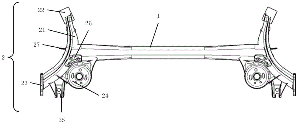
Fig. 1 is a schematic structural diagram of an automotive rear suspension torsion beam assembly according to an embodiment of the present disclosure, and fig. 2 is a partial exploded view of an automotive rear suspension torsion beam assembly according to an embodiment of the present disclosure, please refer to fig. 1-2, where fig. 2 shows an exploded view of a structure of a left half portion in fig. 1, and the automotive rear suspension torsion beam assembly includes: crossbeam 1 and two torsion units 2 connected at this crossbeam 1 both ends symmetrically, every torsion unit 2 includes: the trailing arm 21, the sleeve 22, the hub plate 23, the spring seat 24, and the damper bracket 25; this crossbeam 1 is the tubular structure through cold punching, hydraulic bulging and heat treatment technology shaping, and this crossbeam 1 includes: the cross-sectional structure comprises a V-shaped cross-sectional section 11 and two variable cross-sectional sections 12 symmetrically connected to two ends of the V-shaped cross-sectional section 11, wherein the cross-sectional shapes of the variable cross-sectional sections 12 are as follows: the V shape gradually deforms to the rectangle along the middle part to the end part; the trailing arm 21 comprises an inner plate 211 and an outer plate 212, the inner plate 211 is connected to the end of the beam 1, and the inner plate 211 and the outer plate 212 are connected in a tailor welding manner; the sleeve 22 is connected to the top end of the trailing arm 21; the hub plate 23 is connected to the bottom end of the trailing arm 21; the spring seat 24 is connected between the trailing arm 21 and the cross member 1, and the shock absorber bracket 25 is connected between the trailing arm 21 and the spring seat 24.
The structure and the working principle of the automobile rear suspension torsion beam assembly are specifically described as follows:
the beam 1:
the beam 1 is a tubular structure formed through cold punching, hydraulic expansion and heat treatment processes, the tubular structure ensures the strength and durability of the beam 1, the weight of the beam 1 is reduced, and the lightweight design of the automobile rear suspension torsion beam assembly is realized. The cross beam 1 is preformed by a cold punching process, it should be noted that the cross beam 1 has different cold punching forces in the whole length, so that deformation with different degrees can be formed, wherein for the variable cross section 12, the rectangular cross section of the raw material of the tube body at the end part is not punched, and the transition is gradually carried out to the V-shaped cross section at the middle part, so as to improve the rigidity of the cross beam 1 as much as possible and maintain the stability. The beam 1 is easily and precisely formed by a hydraulic expansion process. The heat treatment process is used for improving the yield and tensile property of the material.
Fig. 3 is a schematic structural diagram of a cross beam 1 of a torsion beam assembly for a rear suspension of an automobile according to an embodiment of the present application, and fig. 4 is a schematic structural diagram of three cross sections a, b, and c of the cross beam 1 of the torsion beam assembly for a rear suspension of an automobile according to an embodiment of the present application, please refer to fig. 3-4, where the cross beam 1 includes: the cross-sectional structure comprises a V-shaped cross-sectional section 11 and two variable cross-sectional sections 12 symmetrically connected to two ends of the V-shaped cross-sectional section 11, wherein the cross-sectional shapes of the variable cross-sectional sections 12 are as follows: the V shape is gradually deformed to the rectangle shape along the middle to the end. The variable cross-section structure improves the yield and tensile properties of the cross beam 1, so that the cross beam can form elastic force based on self torsion, and the inclination degree of wheels on two sides is reduced as resistance.
The trailing arm 21:
fig. 5 is an exploded view of a trailing arm 21 of an automotive rear suspension torsion beam assembly according to an embodiment of the present disclosure, please refer to fig. 5, in which the trailing arm 21 includes an inner plate 211 and an outer plate 212, the inner plate 211 is connected to an end of the cross beam 1, the inner plate 211 and the outer plate 212 are connected by a tailor welding method, and by designing the trailing arm 21 as a structure in which the inner plate 211 and the outer plate 212 are connected by a tailor welding method, strength and fatigue performance of the automotive rear suspension torsion beam assembly are enhanced, and the automotive rear suspension torsion beam assembly has small technical difficulty, low cost, wide material selection range, and greatly enhanced manufacturability of the torsion beam assembly product.
Other structures:
the sleeve 22 is attached to the top end of the trailing arm 21 for attachment of a bushing.
The hub plate 23 is attached to the bottom end of the trailing arm 21 for assembling a hub axle.
The spring seat 24 is connected between the trailing arm 21 and the cross member 1 for mounting a spring.
The damper bracket 25 is connected between the trailing arm 21 and the spring seat 24 for mounting a damper.
The technical scheme that this application embodiment provided, through the structure that connects for inner panel 211 and planking 212 through the tailor-welding mode with trailing arm 21 design, the intensity and the fatigue property of this car rear suspension torsion beam assembly have been strengthened, the technical difficulty is little, the cost is lower, material selection scope is wide, this torsion beam assembly product's manufacturability has been strengthened greatly, through with crossbeam 1 design for the tubular structure through cold punching, the hydraulic bulging and the shaping of thermal treatment process, and design crossbeam 1 into variable cross-section shape, compare in current plate structure, above-mentioned crossbeam 1 is lighter, variable cross-section shape is when satisfying intensity durability, the torsional rigidity of crossbeam 1 has been improved, the stability of operation and the NVH performance of this torsion beam assembly have been promoted, the longitudinal impact bearing capacity of rear axle has been promoted.
The specific structure of the automobile rear suspension torsion beam assembly is further described as follows:
the beam 1:
with continued reference to fig. 3-4, for the beam 1, a heat treatment process is used to improve the yield and tensile properties of the material, for example, the yield strength of the beam 1 after heat treatment can reach 1100 Mpa.
The tube section characteristics of the beam 1 may be as follows: the pipe diameter is 90-100 mm, the weight is 7-8 kg, and compared with the existing plate structure, the whole beam 1 can reduce the weight by 3-4 kg, so that the light weight requirement of the automobile rear suspension torsion beam assembly is met.
The transition of the overlap between the end of the beam 1 and the trailing arm 21 is designed with a large fillet, see a in fig. 4, which may be 30mm, for example. The cross section of the variable cross section 12 of the cross beam 1 gradually changes from a to b and then to c in fig. 4, thereby smoothly transitioning with the V-shaped cross section 11. Wherein the forming process of the variable cross-section 12 may be performed in a plurality of times.
Referring to c in fig. 4, in a possible design, the included angle of the section of the V-shaped section 11 of the cross beam 1 is 50 ° to 60 °, so as to improve the torsion beam mode of the cross beam 1 with small tube diameter and avoid resonance with the wheel cavity mode. The mode refers to the natural vibration characteristics of the structural system. The free vibration of the linear system is decoupled into N orthogonal single degree of freedom vibration systems, corresponding to the N modes of the system. Each mode has a specific natural frequency, damping ratio and mode shape. These modal parameters may be derived by calculation or experimental analysis, such a process of calculation or experimental analysis being referred to as modal analysis. The vibration characteristics of each order mode of the mechanical structure in a certain susceptible frequency range and the vibration response results of the mechanical structure under the excitation action of various vibration sources in the frequency range and inside or outside can be obtained through a structural mode analysis method, and the modal parameters are obtained through the structural mode analysis method and combined with related tests, and the modal parameters are used for redesigning the structure by means of the special parameters.
In a possible design, the length of the V-shaped section 11 of the cross beam 1 is less than 1/2 of the total length of the cross beam 1, and by reducing the length of the V-shaped section 11, the length of the variable section 12 is increased, the mode of the cross beam 1 is improved, and the abnormal sound probability of the cross beam 1 in the twisting process is reduced. For example, the length of both variable section sections 12 may be 363mm, and the length of the V-section 11 may be 426 mm.
Above-mentioned crossbeam 1 structure is through adopting tubular product hydroforming's technology to the laminating clearance about the control crossbeam 1 hydroforming in-process has reduced crossbeam 1's weight when guaranteeing crossbeam 1's intensity and durability, the lightweight design of automobile rear suspension torsion beam assembly has been realized, and improved crossbeam 1's rigidity and kept stability, the yield and the tensile strength of crossbeam 1 have been promoted, cross-sectional design through optimizing crossbeam 1 has satisfied operating stability, NVH and durability.
The trailing arm 21:
fig. 5 is an exploded view of a trailing arm 21 of an automotive rear suspension torsion beam assembly according to an embodiment of the present disclosure, please continue to refer to fig. 5, the trailing arm 21 includes an inner plate 211 and an outer plate 212, wherein the inner plate 211 and the outer plate 212 are both formed by stamping a plate material through a die, and the inner plate 211 and the outer plate 212 are connected to form the trailing arm 21 by tailor welding, which is simple in forming process. Wherein, the plate can adopt a high-strength steel plate with yield of more than 420 MPa. The tailor welding is to weld the sections of the workpieces together, so that the spliced parts are melted and bonded together. The longitudinal impact resistance of the torsion beam can reach more than 7G by the process, and the problem that four-wheel positioning is unqualified due to deformation of the torsion beam longitudinal arm 21 in the use process of a user can be avoided.
The inner plate 211 and the outer plate 212 both have cavities, and after the inner plate 211 and the outer plate 212 are jointed, the internal cavities are also jointed, and after welding, the formed trailing arm 21 has an internal cavity, so that a better weight reduction effect can be achieved.
This inner panel 211 is connected at the tip of this crossbeam 1, connects through the tailor-welding mode between this inner panel 211 and this planking 212, through the structure that connects for inner panel 211 and planking 212 through the tailor-welding mode with trailing arm 21 design, has strengthened the intensity and the fatigue performance of this automobile rear suspension twist beam assembly, and the technical degree of difficulty is little, and the cost is lower, and material selection scope is wide, has strengthened the manufacturability of this twist beam assembly product greatly.
In a possible design, the thickness of the inner plate 211 of the trailing arm 21 is 3mm-5mm, the thickness of the outer plate 212 is 2mm-4mm, and the thickness of the inner plate 211 is larger than that of the outer plate 212, so that the weight reduction effect is obvious, and the strength and the fatigue performance of the product are enhanced. For example, the thickness of the inner plate 211 may be 4mm, and the thickness of the corresponding outer plate 212 may be 3 mm.
Other structures:
in one possible design, the torsion unit 2 further comprises: a reinforcing plate 26; the reinforcing plate 26 is connected among the trailing arm 21, the cross member 1, and the spring seat 24.
The reinforcing plate 26 is formed by cold stamping of a common plate, and trimming is performed on the key material edges in the process.
In one possible design, the thickness of the reinforcement plate 26 is less than 6mm, which reduces weld strength and fatigue damage.
In one possible design, the inner plate 211 of the trailing arm 21 is provided with a positioning hole 2111, and the outer plate 212 of the trailing arm 21 is provided with a positioning member 2121 matching with the positioning hole 2111. During tailor welding, the positioning element 2121 is inserted into the positioning hole 2111, and after positioning, the inner plate 211 and the outer plate 212 are welded and connected together, so that the overall dimension of the formed trailing arm 21 is still accurate on the basis of simplified process.
In one possible design, the positioning element 2121 is a positioning post corresponding to the positioning hole 2111, so that the positioning element 2121 can be inserted into the positioning hole 2111.
In one possible design, the torsion unit 2 further comprises: and a wire harness bracket 27, wherein the wire harness bracket 27 is welded on the end part of the cross beam 1 and used for positioning and limiting cables. The wire harness support 27 may be formed by ordinary cold stamping.
Fig. 6 is a schematic structural view of a hub plate 23 of an automotive rear suspension torsion beam assembly according to an embodiment of the present application, please refer to fig. 6, in a possible design, the trailing arm 21 has a hollow structure, and the lower end opening of the trailing arm 21 corresponds to a through hole 231 on the hub plate 23 for positioning the hub plate 23.
In one possible design, the trailing arm 21 and the hub plate 23 are connected by a hub bracket to provide better positioning and attachment of the hub plate 23.
With continued reference to fig. 6, in one possible design, the hub plate 23 is provided with a plurality of lightening holes 232, which can lighten the weight of the hub plate 23 without affecting the function of the hub plate 23, thereby realizing the lightweight design of the torsion beam assembly of the rear suspension of the automobile. Specifically, the number of the weight-reducing holes 232 may be 4, which is not limited in this embodiment.
The hub plate 23 is machined and formed by laser cutting, forging or cold stamping, and then the parts with high precision requirements.
At the top end of the trailing arm 21, there is an arc-shaped recess for receiving a sleeve 22, the sleeve 22 being attached to the top end of the trailing arm 21, the sleeve 22 being used for attachment of a bushing. The sleeve 22 is cut out of a cylindrical seamless steel pipe, and is required to be delivered in a state after stress relief annealing. The high-strength composite sleeve pipe can ensure strength, has better material elongation, and avoids the risk of cracking of the sleeve pipe 22.
The shock absorber support is formed by cold stamping of a common plate, and trimming is carried out on the key material edges in the process. The shock absorber support is connected with the inner plate 211 of the trailing arm 21 and the cross beam 1 through welding seams and also plays a role of a reinforcing plate 26, so that the strength and fatigue of the welding seams of the cross beam 1 and the trailing arm 21 are reduced, and particularly, holes for positioning and weight reduction can be designed on the shock absorber support in structural design.
The spring seat 24 is formed by cold stamping of a common plate, and trimming is performed on the key material edges in the process. The spring seat 24 is connected with the inner plate 211 of the trailing arm 21 and the cross beam 1 through welding seams, and also plays a role of a reinforcing plate 26, so that the strength and fatigue of the welding seams of the cross beam 1 and the trailing arm 21 are reduced, and particularly, holes for positioning and weight reduction can be designed on the spring seat in structural design.
And in all the sub-parts, carbon dioxide and argon gas arc welding is adopted, and the welded part is called an automobile rear suspension torsion beam assembly.
All the above optional technical solutions may be combined arbitrarily to form optional embodiments of the present application, and are not described herein again.
The technical scheme that this application embodiment provided, through the structure that connects for inner panel 211 and planking 212 through the tailor-welding mode with trailing arm 21 design, the intensity and the fatigue property of this car rear suspension torsion beam assembly have been strengthened, the technical difficulty is little, the cost is lower, material selection scope is wide, this torsion beam assembly product's manufacturability has been strengthened greatly, through with crossbeam 1 design for the tubular structure through cold punching, the hydraulic bulging and the shaping of thermal treatment process, and design crossbeam 1 into variable cross-section shape, compare in current plate structure, above-mentioned crossbeam 1 is lighter, variable cross-section shape is when satisfying intensity durability, the torsional rigidity of crossbeam 1 has been improved, the stability of operation and the NVH performance of this torsion beam assembly have been promoted, the longitudinal impact bearing capacity of rear axle has been promoted.
Furthermore, the cross beam 1 has high yield and tensile strength, the lightweight requirement of the automobile rear suspension torsion beam assembly is met, the torsion beam mode of the small-pipe-diameter cross beam 1 is improved, and resonance with the wheel cavity mode is avoided. The mode refers to the natural vibration characteristics of the structural system.
Above-mentioned crossbeam 1 structure is through adopting tubular product hydroforming's technology to the laminating clearance about the control crossbeam 1 hydroforming in-process has reduced crossbeam 1's weight when guaranteeing crossbeam 1's intensity and durability, the lightweight design of automobile rear suspension torsion beam assembly has been realized, and improved crossbeam 1's rigidity and kept stability, the yield and the tensile strength of crossbeam 1 have been promoted, cross-sectional design through optimizing crossbeam 1 has satisfied operating stability, NVH and durability.
The forming process of the longitudinal arm 21 is simple, the longitudinal shock resistance of the torsion beam can reach more than 7G, the problem that four-wheel positioning is unqualified due to deformation of the torsion beam longitudinal arm 21 in the use process of a user can be avoided, the strength and the fatigue performance of the automobile rear suspension torsion beam assembly are enhanced, the technical difficulty is small, the cost is low, the material selection range is wide, and the manufacturability of the torsion beam assembly product is greatly enhanced.
In a possible design, the thickness of the inner plate 211 of the trailing arm 21 is 3mm-5mm, the thickness of the outer plate 212 is 2mm-4mm, and the thickness of the inner plate 211 is larger than that of the outer plate 212, so that the weight reduction effect is obvious, and the strength and the fatigue performance of the product are enhanced. For example, the thickness of the inner plate 211 may be 4mm, and the thickness of the corresponding outer plate 212 may be 3 mm.
In one possible design, the torsion unit 2 further comprises: a reinforcing plate 26; the reinforcing plate 26 is connected among the trailing arm 21, the cross member 1, and the spring seat 24.
The above description is only exemplary of the present application and should not be taken as limiting, as any modification, equivalent replacement, or improvement made within the spirit and principle of the present application should be included in the protection scope of the present application.