CN114473662A - Crankshaft machining mechanism and crankshaft machining equipment - Google Patents
Crankshaft machining mechanism and crankshaft machining equipment Download PDFInfo
- Publication number
- CN114473662A CN114473662A CN202210081102.5A CN202210081102A CN114473662A CN 114473662 A CN114473662 A CN 114473662A CN 202210081102 A CN202210081102 A CN 202210081102A CN 114473662 A CN114473662 A CN 114473662A
- Authority
- CN
- China
- Prior art keywords
- crankshaft
- spring
- sleeve
- limiting
- mounting
- Prior art date
- Legal status (The legal status is an assumption and is not a legal conclusion. Google has not performed a legal analysis and makes no representation as to the accuracy of the status listed.)
- Granted
Links
Images




Classifications
-
- B—PERFORMING OPERATIONS; TRANSPORTING
- B24—GRINDING; POLISHING
- B24B—MACHINES, DEVICES, OR PROCESSES FOR GRINDING OR POLISHING; DRESSING OR CONDITIONING OF ABRADING SURFACES; FEEDING OF GRINDING, POLISHING, OR LAPPING AGENTS
- B24B5/00—Machines or devices designed for grinding surfaces of revolution on work, including those which also grind adjacent plane surfaces; Accessories therefor
- B24B5/36—Single-purpose machines or devices
- B24B5/42—Single-purpose machines or devices for grinding crankshafts or crankpins
-
- B—PERFORMING OPERATIONS; TRANSPORTING
- B24—GRINDING; POLISHING
- B24B—MACHINES, DEVICES, OR PROCESSES FOR GRINDING OR POLISHING; DRESSING OR CONDITIONING OF ABRADING SURFACES; FEEDING OF GRINDING, POLISHING, OR LAPPING AGENTS
- B24B27/00—Other grinding machines or devices
- B24B27/0023—Other grinding machines or devices grinding machines with a plurality of working posts
-
- B—PERFORMING OPERATIONS; TRANSPORTING
- B24—GRINDING; POLISHING
- B24B—MACHINES, DEVICES, OR PROCESSES FOR GRINDING OR POLISHING; DRESSING OR CONDITIONING OF ABRADING SURFACES; FEEDING OF GRINDING, POLISHING, OR LAPPING AGENTS
- B24B27/00—Other grinding machines or devices
- B24B27/0069—Other grinding machines or devices with means for feeding the work-pieces to the grinding tool, e.g. turntables, transfer means
-
- B—PERFORMING OPERATIONS; TRANSPORTING
- B24—GRINDING; POLISHING
- B24B—MACHINES, DEVICES, OR PROCESSES FOR GRINDING OR POLISHING; DRESSING OR CONDITIONING OF ABRADING SURFACES; FEEDING OF GRINDING, POLISHING, OR LAPPING AGENTS
- B24B41/00—Component parts such as frames, beds, carriages, headstocks
- B24B41/007—Weight compensation; Temperature compensation; Vibration damping
-
- B—PERFORMING OPERATIONS; TRANSPORTING
- B24—GRINDING; POLISHING
- B24B—MACHINES, DEVICES, OR PROCESSES FOR GRINDING OR POLISHING; DRESSING OR CONDITIONING OF ABRADING SURFACES; FEEDING OF GRINDING, POLISHING, OR LAPPING AGENTS
- B24B47/00—Drives or gearings; Equipment therefor
- B24B47/10—Drives or gearings; Equipment therefor for rotating or reciprocating working-spindles carrying grinding wheels or workpieces
- B24B47/12—Drives or gearings; Equipment therefor for rotating or reciprocating working-spindles carrying grinding wheels or workpieces by mechanical gearing or electric power
-
- B—PERFORMING OPERATIONS; TRANSPORTING
- B24—GRINDING; POLISHING
- B24B—MACHINES, DEVICES, OR PROCESSES FOR GRINDING OR POLISHING; DRESSING OR CONDITIONING OF ABRADING SURFACES; FEEDING OF GRINDING, POLISHING, OR LAPPING AGENTS
- B24B49/00—Measuring or gauging equipment for controlling the feed movement of the grinding tool or work; Arrangements of indicating or measuring equipment, e.g. for indicating the start of the grinding operation
- B24B49/08—Measuring or gauging equipment for controlling the feed movement of the grinding tool or work; Arrangements of indicating or measuring equipment, e.g. for indicating the start of the grinding operation involving liquid or pneumatic means
-
- B—PERFORMING OPERATIONS; TRANSPORTING
- B24—GRINDING; POLISHING
- B24B—MACHINES, DEVICES, OR PROCESSES FOR GRINDING OR POLISHING; DRESSING OR CONDITIONING OF ABRADING SURFACES; FEEDING OF GRINDING, POLISHING, OR LAPPING AGENTS
- B24B5/00—Machines or devices designed for grinding surfaces of revolution on work, including those which also grind adjacent plane surfaces; Accessories therefor
- B24B5/35—Accessories
- B24B5/355—Feeding means
-
- B—PERFORMING OPERATIONS; TRANSPORTING
- B24—GRINDING; POLISHING
- B24B—MACHINES, DEVICES, OR PROCESSES FOR GRINDING OR POLISHING; DRESSING OR CONDITIONING OF ABRADING SURFACES; FEEDING OF GRINDING, POLISHING, OR LAPPING AGENTS
- B24B5/00—Machines or devices designed for grinding surfaces of revolution on work, including those which also grind adjacent plane surfaces; Accessories therefor
- B24B5/36—Single-purpose machines or devices
- B24B5/42—Single-purpose machines or devices for grinding crankshafts or crankpins
- B24B5/421—Supports therefor
-
- Y—GENERAL TAGGING OF NEW TECHNOLOGICAL DEVELOPMENTS; GENERAL TAGGING OF CROSS-SECTIONAL TECHNOLOGIES SPANNING OVER SEVERAL SECTIONS OF THE IPC; TECHNICAL SUBJECTS COVERED BY FORMER USPC CROSS-REFERENCE ART COLLECTIONS [XRACs] AND DIGESTS
- Y02—TECHNOLOGIES OR APPLICATIONS FOR MITIGATION OR ADAPTATION AGAINST CLIMATE CHANGE
- Y02P—CLIMATE CHANGE MITIGATION TECHNOLOGIES IN THE PRODUCTION OR PROCESSING OF GOODS
- Y02P70/00—Climate change mitigation technologies in the production process for final industrial or consumer products
- Y02P70/10—Greenhouse gas [GHG] capture, material saving, heat recovery or other energy efficient measures, e.g. motor control, characterised by manufacturing processes, e.g. for rolling metal or metal working
Landscapes
- Engineering & Computer Science (AREA)
- Mechanical Engineering (AREA)
- Constituent Portions Of Griding Lathes, Driving, Sensing And Control (AREA)
Abstract
The application discloses bent axle processing agency and bent axle processing equipment. The crankshaft machining mechanism comprises a limiting tool, a polishing device, an assembling component and a detecting component, the limiting tool is used for installing a crankshaft, the polishing device is installed above the limiting tool and comprises a polishing head, the polishing head can abut against a to-be-polished part of the crankshaft, the to-be-polished part of the crankshaft is polished by the polishing head when the polishing head rotates, the assembling component is installed below the limiting tool, and the detecting component is installed on the assembling component. So, spacing frock can be carried on spacingly so that grinding device can polish to treating of bent axle the position automatically, has guaranteed the grinding quality of the face of polishing, simultaneously, can come to carry out automatic installation to the spring through the assembly subassembly, and need not the manual work and go on, has practiced thrift the human cost, in addition, still can come automatic detection and confirm whether the spring has installed in the assigned position department of bent axle through the determine module, has improved the installation quality.
Description
Technical Field
The application relates to the technical field of crankshaft machining, in particular to a crankshaft machining mechanism and crankshaft machining equipment.
Background
The compressor crankshaft part needs to be provided with a conical spring in a crankshaft bottom hole to a required depth, and simultaneously, before a bearing is installed, the matching surface (namely a thrust surface) of the crankshaft and the bearing inner ring needs to be ground so as to achieve the required surface roughness.
Among the prior art, generally insert a grinding device who is driven by the motor with the bent axle through artifical mode and polish, the grinding quality of bent axle abrasive surface is difficult to the guarantee, and the spring also is installed with the help of the tool by the manual work, and efficiency is lower and extravagant human cost, also can't confirm whether the spring is installed in place during the installation spring simultaneously, influences the installation quality.
Disclosure of Invention
The embodiment of the application provides a crankshaft machining mechanism and crankshaft machining equipment.
The crankshaft machining mechanism comprises a limiting tool, a polishing device, an assembling component and a detecting component, wherein the limiting tool is used for mounting a crankshaft to limit the crankshaft; the grinding device is movably arranged above the limiting tool and comprises a grinding head, the grinding head can move towards one side of the limiting tool to support against a part to be ground of the crankshaft, and the grinding head grinds the part to be ground when rotating; the assembling assembly is movably arranged below the limiting tool and used for installing a spring into a hole position at the bottom of the crankshaft; the detection assembly is installed on the assembly and used for detecting the installation position of the spring.
In the crankshaft machining mechanism of the embodiment, the crankshaft is installed on the limiting tool, the polishing device can move towards the crankshaft direction relative to the limiting tool, the polishing head can abut against the portion to be polished of the crankshaft and polish the portion to be polished through rotation of the polishing head, the spring can be automatically installed on the crankshaft through the assembling assembly, and the detecting assembly can detect the installation position of the spring on the crankshaft to avoid the situation that the spring is not installed in place. So, the spacing frock of accessible comes to carry on spacingly so that grinding device can polish to the waiting position of polishing of bent axle automatically, has guaranteed the grinding quality of the face of polishing, simultaneously, can come to carry out automatic installation to the spring through the assembly subassembly, and need not the manual work and go on, has practiced thrift the human cost, in addition, still can come automated inspection and confirm whether the spring has installed in the assigned position department of bent axle through the determine module, has improved installation quality.
In some embodiments, the polishing device includes a polishing motor and a driving shaft, the driving shaft is connected to the polishing motor, the polishing head is detachably connected to the driving shaft, and the polishing motor is configured to drive the driving shaft to rotate so as to drive the polishing head to rotate, so as to polish the portion to be polished.
In some embodiments, the polishing device further comprises a buffer assembly, the buffer assembly is movably mounted on the driving shaft, the polishing head is detachably mounted on the buffer assembly, the driving shaft can drive the polishing head to rotate through the buffer assembly, and the buffer assembly can slide along the axial direction of the driving shaft relative to the driving shaft under the action of external force.
In some embodiments, the buffering assembly includes a sleeve and a first elastic member installed in the sleeve, one end of the sleeve is sleeved on the driving shaft and movably connected with the driving shaft, the other end of the sleeve is detachably connected with the polishing head, the first elastic member is installed in the sleeve, two ends of the first elastic member respectively abut against the driving shaft and the sleeve, and the first elastic member is used for applying an elastic force to the sleeve in a direction opposite to the driving shaft.
In some embodiments, a limiting groove is formed in a side wall of the sleeve, the limiting groove extends along an axial direction of the sleeve, the buffering assembly further includes a limiting member, the limiting member penetrates through the limiting groove and is fixedly connected with the driving shaft, and the sleeve is in sliding fit with the driving shaft through the limiting member and the limiting groove.
In some embodiments, the number of the limiting grooves is multiple, the limiting grooves are arranged at intervals along the circumferential direction of the sleeve, and the limiting members correspond to the limiting grooves one to one.
In some embodiments, the crankshaft machining mechanism further comprises a lifting motor, the lifting motor is connected with the polishing device, and the lifting motor is used for driving the polishing device to move relative to the limiting tool so that the polishing head abuts against the part to be polished.
In some embodiments, the polishing head is formed with a first axial hole, and the crankshaft extends into the first axial hole toward a shaft section of the polishing device when the polishing head abuts against the portion to be polished.
In some embodiments, a protection member is provided in the polishing head, the protection member is formed with a second shaft hole, the second shaft hole is concentrically arranged with the first shaft hole, the second shaft hole has a diameter smaller than that of the first shaft hole, and the crankshaft extends into the first shaft hole and the second shaft hole toward a shaft section of the polishing device.
In some embodiments, the limiting tool comprises a mounting seat, a mounting hole is formed in the mounting seat, the mounting hole penetrates through the mounting seat, the crankshaft is mounted in the mounting hole, and a stopping structure is formed in the mounting seat and used for abutting against an eccentric section of the crankshaft in the rotation process of the crankshaft to limit the crankshaft in the circumferential direction.
In some embodiments, the stop structure includes a stop pillar disposed on a peripheral side of the mounting hole, and the stop pillar is configured to abut against an eccentric section of the crankshaft during rotation of the crankshaft to limit the crankshaft in a circumferential direction.
In some embodiments, the assembling component comprises a driving member, an assembling seat and a spring pin, the spring pin is arranged on the top surface of the assembling seat, the spring pin is used for placing the spring, and the driving member is used for driving the spring pin to move along the axial direction of the crankshaft so as to install the spring into the hole position at the bottom of the crankshaft.
In some embodiments, the assembling component further includes an assembling member and a second elastic member, the assembling member is connected to the driving member, the assembling seat is movably connected to the assembling member, the driving member is configured to drive the assembling member to move so as to drive the assembling seat to move along an axial direction of the crankshaft, the second elastic member is sleeved on the assembling seat and respectively abuts against the assembling member and the assembling seat, and the second elastic member is configured to apply an elastic force to the assembling seat in a direction opposite to the direction of the assembling member.
In some embodiments, the detection assembly includes a valve and a pneumatic sensor, an air source channel is formed in the assembly seat, the air source channel includes an air inlet and an air outlet, the air outlet is disposed on the top surface of the assembly seat, the valve is mounted on the air inlet, the pneumatic sensor is connected to the valve, the pneumatic sensor is used for detecting air pressure in the valve, and when the spring is mounted in place, the air outlet is sealed under the action of the bottom surface of the crankshaft.
In some embodiments, the detection assembly further comprises a sealing member disposed on top of the mounting seat and covering the air outlet, the sealing member closing the air outlet under the action of the bottom surface of the crankshaft when the spring is in place.
In some embodiments, the sealing member is connected with the mounting seat in a floating manner, and a relief opening is formed in the sealing member and is arranged in a staggered manner with respect to the air outlet opening.
The crankshaft machining apparatus of the embodiment of the present application includes the crankshaft machining mechanism in the above-described embodiment.
Additional aspects and advantages of the present application will be set forth in part in the description which follows and, in part, will be obvious from the description, or may be learned by practice of the present application.
Drawings
The above and/or additional aspects and advantages of the present application will become apparent and readily appreciated from the following description of the embodiments, taken in conjunction with the accompanying drawings of which:
fig. 1 is a schematic plan view of a crankshaft machining apparatus according to an embodiment of the present application;
fig. 2 is a schematic perspective view of a crankshaft machining mechanism according to the embodiment of the present application;
FIG. 3 is a schematic side view of a crankshaft machining mechanism according to an embodiment of the present application;
FIG. 4 is a schematic perspective view of a portion of the grinding apparatus according to an embodiment of the present application;
FIG. 5 is a schematic view of a partial structure plan view of a polishing apparatus according to an embodiment of the present application;
FIG. 6 is a schematic cross-sectional view of the polishing device of FIG. 5 taken along line A-A;
fig. 7 is a schematic perspective view of a limiting tool according to an embodiment of the present application;
FIG. 8 is a schematic cross-sectional structure view of a limiting tool according to an embodiment of the present application;
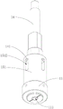
FIG. 9 is a perspective view of a mounting assembly and a sensing assembly according to an embodiment of the present application;
FIG. 10 is a perspective view of a mounting socket and a spring pin according to an embodiment of the present disclosure;
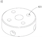
fig. 11 is a perspective view of a seal according to an embodiment of the present application.
Description of the main element symbols:
the crankshaft machining device 1000, the crankshaft machining mechanism 100 and the turntable 200;
the polishing device 10, the polishing head 11, the first shaft hole 111, the protection member 12, the second shaft hole 121, the polishing motor 13, the driving shaft 14, the limiting member 141, the buffer assembly 15, the sleeve 151, the abutting portion 1511, the limiting groove 1512, and the first elastic member 152;
the limiting tool 20, the mounting seat 21, the mounting hole 22, the stopping structure 23 and the stopping column 231;
the assembling component 30, the driving component 31, the assembling seat 32, the air outlet 321, the air inlet 322, the spring pins 33, the supporting rod 34, the mounting component 35 and the second elastic component 36;
a crankshaft 50, a bearing section 51, an eccentric section 52, and a fixed section 53;
a lift motor 60.
Detailed Description
Reference will now be made in detail to embodiments of the present application, examples of which are illustrated in the accompanying drawings, wherein like or similar reference numerals refer to the same or similar elements or elements having the same or similar function throughout. The embodiments described below with reference to the accompanying drawings are illustrative and are only for the purpose of explaining the present application and are not to be construed as limiting the present application.
In the description of the present application, it is to be understood that the terms "center," "longitudinal," "lateral," "length," "width," "thickness," "upper," "lower," "front," "rear," "left," "right," "vertical," "horizontal," "top," "bottom," "inner," "outer," "clockwise," "counterclockwise," and the like are used in an orientation or positional relationship indicated in the drawings for convenience in describing the present application and to simplify the description, and are not intended to indicate or imply that the device or element so referred to must have a particular orientation, be constructed in a particular orientation, and be operated in a particular orientation, and thus are not to be construed as limiting the present application. Furthermore, the terms "first", "second" and "first" are used for descriptive purposes only and are not to be construed as indicating or implying relative importance or implicitly indicating the number of technical features indicated. Thus, features defined as "first", "second", may explicitly or implicitly include one or more of the described features. In the description of the present application, "a plurality" means two or more unless specifically limited otherwise.
In the description of the present application, it should be noted that, unless otherwise explicitly stated or limited, the terms "mounted," "connected," and "connected" are to be construed broadly, and may be, for example, a fixed connection, a detachable connection, or an integral connection; may be mechanically connected, may be electrically connected or may be in communication with each other; either directly or indirectly through intervening media, either internally or in any other relationship. The specific meaning of the above terms in the present application can be understood by those of ordinary skill in the art as appropriate.
In this application, unless expressly stated or limited otherwise, the first feature "on" or "under" the second feature may comprise direct contact of the first and second features, or may comprise contact of the first and second features not directly but through another feature in between. Also, the first feature being "on," "above" and "over" the second feature includes the first feature being directly on and obliquely above the second feature, or merely indicating that the first feature is at a higher level than the second feature. A first feature being "under," "below," and "beneath" a second feature includes the first feature being directly under and obliquely below the second feature, or simply meaning that the first feature is at a lesser elevation than the second feature.
The following disclosure provides many different embodiments or examples for implementing different features of the application. In order to simplify the disclosure of the present application, specific example components and arrangements are described below. Of course, they are merely examples and are not intended to limit the present application. Moreover, the present application may repeat reference numerals and/or letters in the various examples, such repetition is for the purpose of simplicity and clarity and does not in itself dictate a relationship between the various embodiments and/or configurations discussed. In addition, while various specific examples of processes and materials are provided herein, one of ordinary skill in the art will recognize that other processes may be used and/or other materials may be used.
Referring to fig. 1, a crankshaft machining apparatus 1000 according to an embodiment of the present application includes a crankshaft machining mechanism 100 according to an embodiment of the present application. The crankshaft machining apparatus 1000 may be a production line type machining apparatus, and the crankshaft machining apparatus 1000 may perform machining operations such as polishing the crankshaft 50, installing parts on the crankshaft 50, detecting and lubricating the installed parts, so that the crankshaft 50 may be directly installed on a compressor for use after being processed by the crankshaft machining apparatus 1000.
The crankshaft machining apparatus 1000 includes a turntable 200 and a plurality of machining mechanisms disposed on the turntable 200, and the turntable 200 can drive the crankshaft 50 which is not machined to be processed through different machining mechanisms, so that the crankshaft 50 can complete the whole machining process under the driving of the turntable 200. Wherein, crankshaft machining mechanism 100 is one of them ring on the processing line, and when bent axle 50 rotated to crankshaft machining mechanism 100 department under the drive of carousel 200, crankshaft machining mechanism 100 can polish crankshaft 50 and install the spring to the corresponding hole site of bent axle 50 in and detect whether the spring is installed the appointed degree of depth, and then can accomplish the partial processing step of bent axle 50.
The crankshaft processing equipment 1000 may further include an oil blade pre-installation and oil pump housing installation mechanism, an oil blade automatic feeder, an oil blade press-in mechanism, an oil blade and oil pump housing height detection mechanism, a spring automatic feeder, a spring detection and crankshaft exchange mechanism, and the like, and the turntable 200 may drive the crankshaft 50 to sequentially pass through different processing mechanisms for processing so as to complete the whole processing procedure of the crankshaft 50. The present application is not limited to a specific machining mechanism in the crankshaft machining apparatus 1000, and the present application mainly describes the crankshaft machining mechanism 100 in detail.
Referring to fig. 2 and 3, a crankshaft machining mechanism 100 according to an embodiment of the present application includes a polishing device 10, a limiting tool 20, an assembling component 30, and a detecting component 40, where the polishing device 10 is movably installed above the limiting tool 20, the polishing device 10 includes a polishing head 11, the polishing head 11 can move toward one side of the limiting tool 20 to abut against a portion to be polished of a crankshaft 50, and the polishing head 11 polishes the portion to be polished when rotating; the limiting tool 20 is used for installing the crankshaft 50 to limit the crankshaft 50; the assembling component 30 is movably arranged below the limiting tool 20, and the assembling component 30 is used for installing the spring into a hole at the bottom of the crankshaft 50; the detection assembly 40 is mounted on the mounting assembly 30, and the detection assembly 40 is used for detecting the mounting position of the spring.
In the crankshaft machining mechanism 100 of the embodiment of the application, the crankshaft 50 is installed on the limiting tool 20, the grinding device 10 can move towards the crankshaft 50 relative to the limiting tool 20, the grinding head 11 can be abutted to the portion to be ground of the crankshaft 50 and can be ground by the rotation of the grinding head 11, the assembly component 30 can automatically install a spring onto the crankshaft 50, and the detection component 40 can detect the installation position of the spring on the crankshaft 50 to avoid the spring from being installed in place. So, the spacing frock of accessible 20 comes to carry on spacingly so that grinding device 10 can polish to the position of waiting of bent axle 50 automatically, has guaranteed the grinding quality of the face of polishing, simultaneously, can come to carry out automatic installation to the spring through assembly component 30, and need not the manual work and go on, practiced thrift the human cost, in addition, still can come automatic detection and confirm whether the spring has installed in bent axle 50 assigned position department through detecting component 40, improved the installation quality.
Specifically, the limiting tool 20 is movably disposed in the crankshaft machining mechanism 100. In one embodiment, the limiting tool 20 can be driven by the turntable 200 to move to a predetermined station of the crankshaft machining mechanism 100, wherein when the limiting tool 20 is located at the predetermined station, the crankshaft 50 on the limiting tool 20 can correspond to the polishing device 10 above the limiting tool and the assembly component 30 below the limiting tool, so that the polishing device 10 can polish the crankshaft 50 on the limiting tool 20, and meanwhile, the assembly component 30 can also mount the spring in a hole position at the bottom of the crankshaft 50.
Of course, in some other embodiments, the limit tool 20 may be fixed relative to the grinding device 10 and the assembly component 30, and the turntable 200 may mount the crankshaft 50 to the limit tool 20 through other mechanisms when rotating. This application does not do the restriction to this, and spacing frock 20 can place bent axle 50 and carry on spacingly to bent axle 50, be convenient for with grinding device 10 and assembly component 30 cooperation in order to carry out the processing to bent axle 50 can.
The grinding device 10 may be disposed above the limiting tool 20, and the grinding device 10 may be movable in the up-down direction relative to the limiting tool 20. The sanding head 11 may be disposed below the sanding device 10, and the sanding head 11 may include an abrasive wheel, a sanding pad, or the like.
When the limiting tool 20 moves to a preset station, the polishing device 10 moves towards the crankshaft 50, and the polishing head 11 can move downwards along with the crankshaft 50 until the polishing head abuts against a part to be polished of the crankshaft 50. The polishing device 10 can also drive the polishing head 11 to rotate, and then when the polishing head 11 abuts against the part to be polished, the rotating polishing head 11 can polish the part to be polished.
The crankshaft 50 may include a bearing section 51, an eccentric section 52, and a fixed section 53, wherein the bearing section 51 and the fixed section 53 are disposed at both ends of the eccentric section 52. The bearing segment 51 may be used to be coupled with a bearing of a compressor, and the fixing segment 53 may be formed with a spring hole (not shown) on a side facing the assembly 30, and the assembly 30 may mount a spring in the spring hole.
When the crankshaft 50 is placed on the limit tool 20, the bearing section 51 faces the side where the grinding device 10 is located. It is understood that the portion to be ground may be an end surface of the bearing segment 51 facing the grinding device 10, or may be a side surface of the bearing segment 51. The bearing section 51 is eccentrically connected with the eccentric section 52, the shaft diameter of the eccentric section 52 is larger than that of the bearing section 51, and further, the part to be polished can be the end surface of the eccentric section 52 facing one side of the polishing device 10 or the side surface of the eccentric section 52.
It should be noted that the portion to be ground in the embodiment of the present application may be an end surface of the eccentric section 52 facing the grinding device 10. Because the end surface is not smooth when the crankshaft 50 is molded, when the crankshaft 50 is installed on a bearing in a compressor, the end surface may scratch the bearing or increase the friction between the end surface and the bearing when being in running fit with the bearing to influence the rotation of the crankshaft 50 in the compressor, and then the end surface needs to be polished smoothly by the polishing device 10, so that the service lives of the crankshaft 50 and the bearing can be prolonged, the service life of the compressor is further prolonged, meanwhile, the working efficiency of the crankshaft 50 during rotation can be enhanced, and the output power of the compressor is enhanced. Of course, in some other embodiments, the grinding device 10 can also grind other portions of the crankshaft 50, and the application is not limited to the portion of the crankshaft 50 to be ground.
The assembling component 30 may be disposed below the position limiting tool 20, and the assembling component 30 may also be capable of moving in the vertical direction relative to the position limiting tool 20. After the grinding device 10 finishes grinding the crankshaft 50, the grinding device 10 continues to abut against the crankshaft 50 so that the crankshaft 50 is relatively fixed on the limiting tool 20.
The assembly component 30 moves upwards to install the spring into the spring hole on the fixing section 53 of the crankshaft 50, and due to the fixing of the grinding device 10 and the limiting tool 20, the crankshaft 50 cannot move under the upward abutting of the assembly component 30, and the spring can be installed into the position with the designated depth in the spring hole under the action of the assembly component 30.
The spring may be a conical spring, and the application does not limit the type of the spring. When the crankshaft 50 rotates in the compressor, the spring can enable the crankshaft 50 to have a certain buffering allowance along the axial direction of the crankshaft, so that the crankshaft 50 is prevented from rigidly colliding with the inner wall of the compressor in the rotating process, and the crankshaft 50 and the compressor are further protected to a certain extent.
The detection assembly 40 may detect the installation position of the spring by detecting airtightness between the crankshaft 50 and the fitting assembly 30. When the assembling component 30 moves upwards, if the air tightness between the crankshaft 50 and the assembling component 30 is poor, the spring is not installed at the position with the designated depth, and the detection component 40 gives a prompt and drives the assembling component 30 to continue moving upwards to install the spring at the position with the designated depth; if the air tightness between the crankshaft 50 and the assembling component 30 is good, which means that the spring is installed in place, the assembling device can be driven to move downwards, so that the assembling device is separated from the crankshaft 50, and the assembling of the spring is completed.
Of course, the detection assembly 40 can also detect the installation position of the spring in the hole site through other modes, and the application does not limit this, and it is enough to detect whether the spring is installed to the established position.
Referring to fig. 2-6, in some embodiments, the sanding head 11 is formed with a first axial hole 111, and the crankshaft 50 extends into the first axial hole 111 toward the shaft section of the sanding device 10 when the sanding head 11 abuts against the portion to be sanded.
In this manner, when the sanding head 11 is sanding, the bearing section 51 can extend into the first shaft hole 111, so that the bottom of the sanding head 11 can sand the top surface of the eccentric section 52 without affecting the bearing section 51.
Specifically, the portion to be ground may be the top surface of the eccentric section 52. First shaft hole 111 can set up the central point who puts in sanding head 11 bottoms, and first shaft hole 111 can run through in sanding head 11 along its axial direction, and then when treating the position of polishing and polish, bearing section 51 can stretch into to first shaft hole 111 in for sanding head 11's bottom surface can support with treating the position of polishing and hold, and then can treat when sanding head 11 rotates and polish the position.
It should be noted that the aperture of the first shaft hole 111 may be larger than the diameter of the bearing section 51, and when the bearing section 51 extends into the first shaft hole 111, the bearing section 51 is spaced from the inner wall of the first shaft hole 111. The side walls of the bearing section 51 do not rub against the inner wall of the first shaft hole 111 to cause scoring when the sanding head 11 rotates.
Of course, when the portion to be ground is the side surface of the bearing segment 51, the diameter of the first shaft hole 111 may be adapted to the diameter of the bearing segment 51, so that the side surface of the bearing segment 51 can be ground better. The application does not limit the aperture and the specific structure of the first shaft hole 111, and the first shaft hole 111 can be selectively arranged according to different positions of the polishing head 11.
Referring to fig. 2 to 6, in some embodiments, the protection member 12 is disposed in the polishing head 11, the protection member 12 is formed with a second shaft hole 121, the second shaft hole 121 is concentric with the first shaft hole 111, the diameter of the second shaft hole 121 is smaller than that of the first shaft hole 111, and the crankshaft 50 extends into the first shaft hole 111 and the second shaft hole 121 toward a shaft section of the polishing device 10.
Thus, when the bearing segment 51 extends into the first shaft hole 111, the protection member 12 can protect the bearing segment 51, so that the sidewall of the bearing segment 51 and the inner wall of the first shaft hole 111 are always kept at an interval, and the occurrence of scratches caused by the friction between the sidewall of the bearing segment 51 and the inner wall of the first shaft hole 111 is avoided.
Specifically, the protector 12 may be made of plastic or plastic, and the hardness of the protector 12 is less than that of the crankshaft 50. The protector 12 may be provided inside the sanding head 11. The second shaft hole 121 is disposed through the protector 12, and the second shaft hole 121 coincides with the center of the first shaft hole 111, so that the bearing segment 51 can sequentially pass through the first shaft hole 111 and the second shaft hole 121 when the sanding device 10 moves downward.
It should be noted that the diameter of the second shaft hole 121 needs to be smaller than the diameter of the first shaft hole 111 and not smaller than the diameter of the bearing section 51, so that the bearing section 51 can avoid friction collision with the inner wall of the first shaft hole 111 under the restriction of the second shaft hole 121 during the rotation of the sanding head 11. The inner wall of the second shaft hole 121 is smoothly arranged, so that the peripheral wall of the bearing segment 51 can be further protected, and the influence on the connection between the bearing segment 51 and the bearing due to scratch is avoided.
Referring to fig. 2 and 3, in some embodiments, the crankshaft machining mechanism 100 further includes a lifting motor 60, the lifting motor 60 is connected to the polishing device 10, and the lifting motor 60 is configured to drive the polishing device 10 to move relative to the limiting tool 20 so that the polishing head 11 abuts against the portion to be polished.
In this way, the grinding device 10 can move up and down relative to the limiting tool 20 under the driving of the lifting motor 60 so that the grinding head 11 can abut against the part to be ground of the crankshaft 50.
Specifically, lift motor 60 may be a servo motor. The lift motor 60 may be disposed above the grinding apparatus 10 to drive the grinding apparatus 10 to move. Of course, the lifting motor 60 may also be disposed on the side of the polishing apparatus 10, and the application does not limit the position of the lifting motor 60.
When the lifting motor 60 drives the polishing device 10 to move downwards, the polishing head 11 can abut against the part to be polished so that the polishing head 11 can polish the part to be polished. After polishing is completed and the spring is installed in place, the lifting motor 60 can drive the polishing device 10 to move upwards, so that the limiting tool 20 can be driven by the turntable 200 to move to the next processing station.
Referring to fig. 2-6, in some embodiments, the polishing device 10 includes a polishing motor 13 and a driving shaft 14, the driving shaft 14 is connected to the polishing motor 13, the polishing head 11 is detachably connected to the driving shaft 14, and the polishing motor 13 is configured to drive the driving shaft 14 to rotate to drive the polishing head 11 to rotate, so as to polish a portion to be polished.
In this way, the polishing head 11 can rotate under the driving of the polishing motor 13 and the driving shaft 14, and further polish the position of the crankshaft 50 to be polished.
Specifically, the grinding motor 13 may be disposed at the top of the grinding device 10, and the grinding motor 13 may be connected to the lift motor 60. A driving shaft 14 is provided below the grinding motor 13, and the driving shaft 14 can be rotated by the grinding motor 13. The drive shaft 14 may be provided in a cylindrical configuration to facilitate rotation.
The sanding head 11 is detachably connected below the driving shaft 14, and the sanding head 11 can rotate under the driving shaft 14.
Since the grinding device 10 can grind different parts of the crankshaft 50, the grinding head 11 can be detachably connected to facilitate replacement of the grinding head 11. For example, when grinding crankshafts 50 of different shaft diameters or different lengths, the corresponding grinding heads 11 may be replaced to grind different portions of the crankshafts 50.
Referring to fig. 4-6, in some embodiments, the grinding device 10 further includes a buffer assembly 15, the buffer assembly 15 is movably mounted on the driving shaft 14, the grinding head 11 is detachably mounted on the buffer assembly 15, the driving shaft 14 can drive the grinding head 11 to rotate through the buffer assembly 15, and the buffer assembly 15 can slide relative to the driving shaft 14 in the axial direction of the driving shaft 14 under the action of external force.
Therefore, when the lifting motor 60 drives the grinding device 10 to move downwards, the grinding head 11 and the crankshaft 50 are prevented from being rigidly abutted and collided to damage the grinding head 11 or the crankshaft 50, and meanwhile, the grinding head 11 can grind the part to be ground more uniformly and smoothly.
Specifically, the cushion assembly 15 is movable in its axial direction with respect to the drive shaft 14 by the urging force between the sanding head 11 and the crankshaft 50, the sanding head 11 being detachably attached to the bottom end of the cushion assembly 15. In the process that the lifting motor 60 drives the polishing device 10 to move downwards, after the polishing head 11 abuts against the part to be polished, the lifting motor 60 can continue to drive the polishing device 10 to move downwards for a certain distance, and the buffer assembly 15 can slide upwards relative to the driving shaft 14 under the action of driving force, so that the polishing head 11 is prevented from rigidly abutting against the crankshaft 50.
Meanwhile, under the condition that the polishing head 11 abuts against the crankshaft 50, the buffer assembly 15 further has downward elastic force on the polishing head 11 along the axial direction of the buffer assembly, so that the polishing head 11 is attached to a part to be polished more tightly, when the polishing head 11 is driven by the polishing motor 13 to rotate, the polishing head 11 always has a certain abutting force on the part to be polished, the friction force between the polishing head 11 and a polishing surface is larger and more uniform, the polishing surface can be polished more uniformly and smoothly, and the polishing quality is enhanced.
Referring to fig. 4-6, in some embodiments, the buffering assembly 15 includes a sleeve 151 and a first elastic member 152 installed in the sleeve 151, wherein one end of the sleeve 151 is sleeved on the driving shaft 14 and movably connected to the driving shaft 14, and the other end is detachably connected to the polishing head 11;
the first elastic member 152 is installed in the sleeve 151, two ends of the first elastic member 152 respectively abut against the driving shaft 14 and the sleeve 151, and the first elastic member 152 is used for applying an elastic force to the sleeve 151 in a direction opposite to the driving shaft 14.
In this way, the buffer assembly 15 may be movably connected to the driving shaft 14 through the sleeve 151, and the first elastic member 152 inside the sleeve 151 abuts against the driving shaft 14 and the sleeve 151 to provide an elastic force to the sleeve 151, so that the polishing head 11 at the bottom of the sleeve 151 can more tightly abut against the portion to be polished.
Specifically, the sleeve 151 may be a hollow cylindrical structure, and the upper end of the sleeve 151 is sleeved at the bottom of the driving shaft 14 and is movably connected with the driving shaft 14 in a gap. That is, the sleeve 151 is not only movable in its axial direction relative to the drive shaft 14, but also movable in its radial direction to a small extent relative to the drive shaft 14. On the one hand, be convenient for cup joint between sleeve 151 and the drive shaft 14, on the other hand, when sleeve 151 rotated, can also make the head of polishing 11 also can have certain activity in radial direction, be convenient for the head of polishing 11 with bent axle 50 counterpoint and make the polishing of head of polishing 11 to bent axle 50 can be more even.
It should be noted that the gap between the inner wall of the sleeve 151 and the outer wall of the drive shaft 14 may range from 0.3mm to 1 mm. Or it can be understood that the difference in diameter between the inner diameter of the upper end of the sleeve 151 and the outer diameter of the bottom end of the drive shaft 14 ranges between 0.3mm and 1 mm. The size of the gap between the sleeve 151 and the drive shaft 14 is not particularly limited in the present application.
The sleeve 151 may have a supporting portion 1511 formed therein, and the first elastic member 152 is disposed in the sleeve 151, and has one end supported on the bottom surface of the driving shaft 14 and the other end supported on the supporting portion 1511. The abutting portion 1511 may be a step structure formed by protruding the inside of the sleeve 151 toward the center, and the bottom periphery of the first elastic member 152 can abut against the step structure.
When the first elastic member 152 is installed inside the sleeve 151, the first elastic member 152 may be in an original length state or a compressed state, and the first elastic member 152 has a downward elastic force on the sleeve 151. When the lifting motor 60 drives the polishing device 10 to move downwards, after the polishing head 11 abuts against the part to be polished, the driving shaft 14 continues to move downwards relative to the sleeve 151, the first elastic member 152 is gradually compressed under the action of the driving shaft 14, and further the first elastic member 152 has a corresponding elastic force on the sleeve 151, so that the sleeve 151 and the polishing head 11 mounted at the lower end of the sleeve 151 are tightly attached to the part to be polished. Therefore, when the polishing head 11 rotates, the friction force between the polishing head and the part to be polished has larger friction force, so that the polishing head 11 can polish the part to be polished more uniformly and smoothly.
Referring to fig. 4-6, in some embodiments, the circumferential wall of the sleeve 151 forms a limiting groove 1512, an extending direction of the limiting groove 1512 may be an axial direction of the sleeve 151, the buffering assembly 15 further includes a limiting member 141, the limiting member 141 is disposed in the limiting groove 1512 and fixedly connected to the driving shaft 14, and the sleeve 151 is slidably connected to the driving shaft 14 through the matching of the limiting member 141 and the limiting groove 1512.
Thus, the sleeve 151 can slide relative to the driving shaft 14 along the extending direction of the limiting groove 1512, and it can be avoided that when the polishing device 10 moves upwards, the sleeve 151 is separated from the driving shaft 14, and meanwhile, when the driving shaft 14 rotates, the limiting part 141 and the limiting groove 1512 are matched to enable the sleeve 151 to rotate along with the driving shaft 14, so as to drive the polishing head 11 to rotate to polish a to-be-polished part.
Specifically, the limiting groove 1512 may be formed on a sidewall of an upper end of the sleeve 151, and the limiting groove 1512 may penetrate through the sidewall of the sleeve 151 to communicate with the hollow structure inside the sleeve 151. The limiting groove 1512 may be a bar shape extending from top to bottom along the axial direction.
The stopper 141 is coupled to a lower end side wall of the driving shaft 14 through the stopper groove 1512. The retaining member 141 may include a screw, a latch, or other fasteners, such that the retaining member 141 is removably coupled to the drive shaft 14 to facilitate the attachment and detachment of the sleeve 151. Of course, in some other embodiments, the limiting member 141 may also be a limiting post formed by the sidewall of the driving shaft 14 protruding outwards, so that the connection between the limiting member 141 and the driving shaft 14 is more stable, and the engagement between the limiting member 141 and the limiting groove 1512 is more secure. The limiting element 141 is not limited in the present application.
When the sanding head 11 does not abut against the crankshaft 50, the retaining member 141 is retained in the upper portion of the retaining groove 1512, and even if the first elastic member 152 has a downward elastic force on the sleeve 151, the sleeve 151 does not disengage from the drive shaft 14. When the polishing device 10 gradually moves downward and abuts against the crankshaft 50, the limiting member 141 gradually moves downward along the limiting groove 1512 along with the driving shaft 14, and the driving shaft 14 can move downward more smoothly under the guidance of the limiting member 141 and the limiting groove 1512. Meanwhile, when the grinding motor 13 drives the driving shaft 14 to rotate, the limiting member 141 is clamped with the side wall of the limiting groove 1512, so as to drive the sleeve 151 to rotate, and the sleeve 151 can further drive the grinding head 11 to rotate to grind the portion to be ground.
Referring to fig. 4-6, in some embodiments, the number of the limiting grooves 1512 is multiple, the limiting grooves 1512 are disposed at intervals along the circumferential direction of the sleeve 151, and the limiting members 141 correspond to the limiting grooves 1512 one by one.
Thus, the movable connection between the sleeve 151 and the driving shaft 14 is more stable, and the driving shaft 14 can drive the sleeve 151 to rotate better.
Specifically, the number of the limiting grooves 1512 may be two, three, four, or the like, and the limiting grooves 1512 are disposed at intervals along the circumferential direction of the sleeve 151 and in parallel, so that when the driving shaft 14 slides relative to the sleeve 151, the limiting members 141 can smoothly move in the limiting grooves 1512.
Referring to fig. 2, 7 and 8, in some embodiments, the limiting tool 20 includes a mounting seat 21, a mounting hole 22 is formed on the mounting seat 21, the mounting hole 22 penetrates through the mounting seat 21, and the crankshaft 50 is installed in the mounting hole 22.
Meanwhile, a stopper structure 23 is formed on the mounting seat 21, and the stopper structure 23 is used for abutting against the eccentric section 52 of the crankshaft 50 during the rotation of the crankshaft 50 so as to limit the crankshaft 50 in the circumferential direction.
So, bent axle 50 can place on mount pad 21 through mounting hole 22, when polishing head 11 rotated crankshaft 50 and polished, detent structure 23 can restrict bent axle 50 with bent axle 50 cooperation and rotate for polishing head 11 can relative motion with bent axle 50, and then produces better power of polishing, and the effect of polishing is better and efficiency is higher.
Specifically, when the crankshaft 50 is installed in the installation hole 22, the fixed section 53 extends into the installation hole 22, and the bottom surface of the eccentric section 52 is attached to the top surface of the installation seat 21. The diameter of the mounting hole 22 can be adapted to the diameter of the fixing section 53 of the crankshaft 50, so as to prevent the crankshaft 50 from inclining to the circumferential side when being mounted in the mounting hole 22, and thus, the alignment with the upper polishing device 10 and the lower assembling component 30 is not affected.
Since the bearing section 51 of the crankshaft 50 extends into the polishing head 11 and the bottom end of the polishing head 11 abuts against the eccentric section 52 during the polishing process, the polishing head 11 may drive the crankshaft 50 to rotate during the polishing rotation, so that the polishing head 11 cannot effectively polish the portion to be polished.
The stopper structure 23 may be provided on the top surface of the mounting seat 21 and on the circumferential side of the mounting hole 22. Because the shaft diameter of the eccentric section 52 is greater than the shaft diameters of the bearing section 51 and the fixed section 53 and is eccentrically arranged relative to the bearing section 51 and the fixed end, when the crankshaft 50 is driven by the polishing head 11 to rotate, the eccentric section 52 can abut against the stop structure 23 on the peripheral side of the eccentric section, the stop structure 23 can limit the crankshaft 50 to rotate along with the polishing head 11, and the polishing head 11 can rotate relative to the part to be polished, so that the polishing head 11 can polish the top surface of the eccentric section 52 better, the polishing effect is better, and the efficiency is higher.
Referring to fig. 7 and 8, in some embodiments, the stopping structure 23 includes a stopping post 231, the stopping post 231 is disposed on the periphery of the mounting hole 22, and the stopping post 231 is configured to abut against the eccentric section 52 of the crankshaft 50 during the rotation of the crankshaft 50 to limit the crankshaft 50 in the circumferential direction. In this way, the stopper pin may abut against the eccentric section 52 when the crankshaft 50 rotates following the polishing head 11 to restrict the rotation of the crankshaft 50.
Specifically, the stopper 231 may be formed by upwardly protruding from the top surface of the mounting seat 21, and the stopper 231 is disposed on the circumferential side of the mounting hole 22 and within the rotation range of the eccentric section 52, so as to be able to restrict the rotation of the crankshaft 50. Preferably, the stop post 231 is made of a material with a low hardness, such as plastic or plastic, so as to avoid the damage to the crankshaft 50 caused by collision with the crankshaft 50.
Of course, in some other embodiments, the stop structure 23 may limit the rotation of the crankshaft 50 in other forms, which is not limited in this application.
Referring to fig. 2 and 9, in some embodiments, the mounting assembly 30 includes a spring pin 33, a mounting seat 32, and a driving member 31, the spring pin 33 is used for placing a spring, the spring pin 33 is disposed on a top surface of the mounting seat 32, and the driving member 31 is used for driving the spring pin 33 to move along an axial direction of the crankshaft 50 to mount the spring in a hole at the bottom of the crankshaft 50.
In this way, the driving member 31 can drive the mounting seat 32 to move up and down along the axial direction, so that the spring pins 33 on the mounting seat 32 can extend into the spring holes at the bottom of the crankshaft 50 to mount the springs into the spring holes.
Specifically, the driving member 31 may include a cylinder, a telescopic mechanism, and other driving elements, and the driving member 31 may be disposed below the position limiting tool 20. The assembly seat 32 can be connected in the top of driving piece 31, and spring pin 33 can set up on the top surface of assembly seat 32 and relative with mounting hole 22 on the spacing frock 20 in upper and lower direction, and the spring can be placed on spring pin 33, and then when driving piece 31 drive assembly seat 32 upward movement, spring pin 33 can stretch into to mounting hole 22 in to in the spring hole of the fixed section 53 bottom with spring mounting to bent axle 50.
As can be seen from the above, the grinding device 10 will abut against the crankshaft 50 during grinding to relatively fix the crankshaft 50 on the limiting tool 20, and the grinding step of the crankshaft 50 by the grinding device 10 may be set before the spring installation step. And then. It can be understood that, when the assembly component 30 installs the spring, the grinding device 10 needs to be engaged above to enable the crankshaft 50 to be continuously fixed on the limiting tool 20, so that the phenomenon that the crankshaft 50 is jacked up when the assembly component 30 installs the spring upwards, so that the spring cannot be installed in place, and the installation quality is affected can be avoided.
Referring to fig. 9 and 10, in some embodiments, the assembly component 30 further includes a second elastic member 36 and a mounting member 35, the mounting member 35 is connected to the driving member 31, the assembly seat 32 is movably connected to the mounting member 35, and the driving member 31 is configured to drive the mounting member 35 to move so as to drive the assembly seat 32 to move along the axial direction of the crankshaft 50;
the second elastic element 36 is sleeved on the mounting seat 32, two ends of the second elastic element respectively abut against the mounting element 35 and the mounting seat 32, and the second elastic element 36 is used for applying an elastic force to the mounting seat 32 in a direction opposite to the mounting element 35.
In this way, the assembly seat 32 is movably connected to the mounting member 35, and the second elastic member 36 is engaged to prevent the assembly component 30 from rigidly colliding with the bottom surface of the crankshaft 50 when moving upward, so that the second elastic member 36 can play a certain role in buffering.
In particular, the mounting member 35 may be provided as a plate-like structure, and the mounting member 35 is fixedly coupled to the top of the driving member 31. The mounting socket 32 is mounted above the mounting member 35. In some embodiments, the bottom of the mounting seat 32 may be provided with a supporting rod 34, the supporting rod 34 is slidably connected with the mounting component 35, the second elastic component 36 may be sleeved on the periphery of the supporting rod 34, the upper end of the second elastic component 36 abuts against the bottom of the mounting seat 32, and the lower end abuts against the top surface of the mounting component 35. The second elastic member 36 always has a certain elastic force on the upper mounting seat 32 under the support of the mounting member 35, and the greater the compression degree of the second elastic member 36, the greater the elastic force provided to the mounting seat 32.
It will be understood that when the driving member 31 drives the mounting seat 32 to move upward to abut against the crankshaft 50, the supporting rod 34 can move downward relative to the mounting member 35 under the abutting force. While the second elastic member 36 is compressed, the second elastic member 36 has an elastic force against the upper mounting seat 32 supported by the bottom mounting member 35, so that the spring pin 33 can mount the spring at a designated depth in the spring hole. Furthermore, the second elastic element 36 not only prevents the mounting seat 32 from rigidly colliding with the bottom of the crankshaft 50, but also provides a certain guarantee for the spring to be mounted in place.
Referring to fig. 9 and 10, in some embodiments, the detecting assembly 40 includes a valve 41 and a pressure sensor (not shown), an air supply passage (not shown) is formed in the mounting seat 32, the air supply passage includes an air inlet 322 and an air outlet 321, and the air outlet 321 is disposed on the top surface of the mounting seat 32;
the valve 41 is installed on the inlet 322, the air pressure sensor is connected to the valve 41, the air pressure sensor is used for detecting the air pressure in the valve 41, and the outlet 321 is closed under the action of the bottom surface of the crankshaft 50 when the spring is installed at a designated position.
Thus, when the assembling seat 32 abuts against the bottom of the crankshaft 50, the bottom surface of the crankshaft 50 can cover the air outlet 321 to block the air outlet 321 from exhausting, and then the air pressure in the air source channel can be detected by the air pressure sensor to confirm whether the bottom surface of the crankshaft 50 is completely attached to the top surface of the assembling seat 32, so that whether the spring is installed in place by the spring inserting pin 33 can be judged.
Specifically, the air supply passage may be disposed inside the mounting seat 32, the air inlet 322 may be disposed at a side surface of the mounting seat 32, the air outlet 321 may be disposed at a top surface of the mounting seat 32, and the valve 41 is connected at the air inlet 322. The valve 41 may be a double-ended valve 41, one end of which is used to connect a gas supply device such as a gas cylinder or a gas pump, and the other end of which is used to connect a pressure sensor, and the pressure sensor can detect the pressure in the gas source channel.
It should be noted that, spring pin 33 is detachable connection on assembly seat 32, and then can change spring pin 33 according to the installation of different springs and with spring mounting to the position of the different degree of depth, and then ensure that the laminating of crankshaft 50 bottom surface and assembly seat 32 top surface can be with spring mounting to the assigned position when blockking out to give vent to anger.
In some embodiments, the air pressure sensor may be provided with an alarm system, for example, the air pressure sensor may send a signal to alert that the spring is installed when the air pressure in the air supply passage reaches a set threshold, and the air pressure long safety device may not send a signal when the air pressure in the air supply passage does not reach the set threshold.
Referring to fig. 9 and 10, in some embodiments, the detecting assembly 40 further includes a sealing member 42, the sealing member 42 is disposed on the top of the mounting seat 32 and covers the air outlet 321, and when the spring is mounted in place, the sealing member 42 seals the air outlet 321 under the action of the bottom surface of the crankshaft 50.
In this way, the sealing member 42 can further enhance the sensitivity of the detecting assembly 40, so that the air tightness between the crankshaft 50 and the mounting seat 32 is better, and the air pressure sensor can more sensitively detect the air pressure in the origin channel, thereby avoiding the air leakage from affecting the detection effect.
Specifically, the sealing element 42 may be made of a metal material, and a position where the sealing element is aligned with the air outlet 321 may be matched with rubber to enhance a sealing effect, which is not limited in the present application. The sealing member 42 may be provided as a cap-like structure, and the sealing member 42 is snapped on the top surface of the mounting seat 32. The sealing member 42 may be in clearance connection with the mounting seat 32, for example, the sealing member 42 may be provided with a screw hole on a side surface, and connected with the mounting seat 32 through a screw, wherein a hole diameter of the screw hole is larger than a diameter of the screw, so that the sealing member 42 can be blown up when the air outlet 321 is exhausted, and the air flow can be flowed out through the clearance to keep the air pressure constant.
It should be noted that, when the spring is mounted at a specific position, that is, when the bottom surface of the crankshaft 50 is tightly attached to the top surface of the sealing member 42, the bottom of the crankshaft 50 applies pressure to the sealing member 42, so that the sealing member 42 blocks the air outlet 321, the air pressure in the air supply passage is increased, and it can be determined that the spring is mounted in place. When the spring is not mounted in place, the air flow discharged from the air outlet 321 is discharged through the gap between the sealing member 42 and the mounting seat 32, and the air inlet and outlet are maintained constant, so that the air pressure value is not changed, and it can be determined that the spring is not mounted in place.
Referring to fig. 9-11, in some embodiments, the sealing member 42 is connected to the mounting seat 32 in a floating manner, and the sealing member 42 is formed with a gas release opening 421, and the gas release opening 421 is disposed in a staggered manner from the gas outlet 321.
In this way, the air release opening 421 can release the air flow discharged from the air outlet 321, so as to avoid the gap between the sealing member 42 and the mounting seat 32 from being unable to discharge all the air flowing out from the air outlet 321 to affect the detection effect.
Specifically, a relief opening 421 may be formed in the top surface of seal member 42. The plurality of the air release ports 421 may be provided, and the plurality of the air release ports 421 are provided at intervals. When the sealing member 42 is mounted, the air release hole 421 and the air outlet 321 are misaligned, and when the crankshaft 50 applies pressure to the sealing member 42, the sealing member 42 blocks the air outlet 321 to discharge air.
The setting of gas release 421 makes sealing member 42 can be better to the gas flow of gas outlet 321 gassing, when the spring was not installed in place for the gas flow circulation nature of gas outlet 321 exhaust is better, keeps the invariant of atmospheric pressure value, further strengthens the sensitivity of detecting component 40, avoids appearing the error.
In the description herein, references to the description of the terms "one embodiment," "certain embodiments," "an illustrative embodiment," "an example," "a specific example," or "some examples" or the like mean that a particular feature, structure, material, or characteristic described in connection with the embodiment or example is included in at least one embodiment or example of the present application. In this specification, schematic representations of the above terms do not necessarily refer to the same embodiment or example. Furthermore, the particular features, structures, materials, or characteristics described may be combined in any suitable manner in any one or more embodiments or examples.
While embodiments of the present application have been shown and described, it will be understood by those of ordinary skill in the art that: numerous changes, modifications, substitutions and alterations can be made to the embodiments without departing from the principles and spirit of the application, the scope of which is defined by the claims and their equivalents.
Claims (17)
1. A crankshaft machining mechanism, comprising:
the limiting tool is used for mounting a crankshaft to limit the crankshaft;
the grinding device is movably arranged above the limiting tool and comprises a grinding head, the grinding head can move towards one side of the limiting tool to support the part of the crankshaft to be ground, and the grinding head grinds the part of the crankshaft to be ground when rotating;
the assembling assembly is movably arranged below the limiting tool and used for installing a spring into a hole position at the bottom of the crankshaft; and
the detection assembly is installed on the assembly and used for detecting the installation position of the spring.
2. The crankshaft machining mechanism according to claim 1, wherein the grinding device comprises a grinding motor and a driving shaft, the driving shaft is connected to the grinding motor, the grinding head is detachably connected to the driving shaft, and the grinding motor is configured to drive the driving shaft to rotate so as to drive the grinding head to rotate, so as to grind the part to be ground.
3. The crankshaft machining mechanism according to claim 2, wherein the grinding device further comprises a buffer assembly, the buffer assembly is movably mounted on the driving shaft, the grinding head is detachably mounted on the buffer assembly, the driving shaft can drive the grinding head to rotate through the buffer assembly, and the buffer assembly can slide relative to the driving shaft in the axial direction of the driving shaft under the action of external force.
4. The crankshaft machining mechanism according to claim 3, wherein the buffering assembly comprises a sleeve and a first elastic member installed in the sleeve, one end of the sleeve is sleeved on the driving shaft and movably connected with the driving shaft, the other end of the sleeve is detachably connected with the polishing head, the first elastic member is installed in the sleeve, two ends of the first elastic member respectively abut against the driving shaft and the sleeve, and the first elastic member is used for applying an elastic force to the sleeve in a direction opposite to the driving shaft.
5. The crankshaft machining mechanism according to claim 4, wherein a limiting groove is formed in a side wall of the sleeve, the limiting groove extends in an axial direction of the sleeve, the buffering assembly further includes a limiting member, the limiting member penetrates through the limiting groove and is fixedly connected with the driving shaft, and the sleeve is slidably fitted with the driving shaft through the limiting member and the limiting groove.
6. The crankshaft machining mechanism according to claim 5, wherein the number of the limiting grooves is plural, the plural limiting grooves are arranged at intervals in the circumferential direction of the sleeve, and the limiting members correspond to the limiting grooves one to one.
7. The crankshaft machining mechanism according to claim 1, further comprising a lifting motor, wherein the lifting motor is connected with the grinding device, and the lifting motor is used for driving the grinding device to move relative to the limiting tool so that the grinding head abuts against the part to be ground.
8. The crankshaft machining mechanism according to claim 1, wherein the grinding head is formed with a first shaft hole, and the crankshaft extends into the first shaft hole toward a shaft section of the grinding device when the grinding head abuts against the portion to be ground.
9. The crankshaft machining mechanism according to claim 8, wherein a protector is provided in the grinding head, the protector is formed with a second shaft hole, the second shaft hole is provided concentrically with the first shaft hole, a diameter of the second shaft hole is smaller than a diameter of the first shaft hole, and the crankshaft extends into the first shaft hole and the second shaft hole toward a shaft section of the grinding device.
10. The crankshaft machining mechanism according to claim 1, wherein the limiting tool comprises a mounting seat, a mounting hole is formed in the mounting seat, the mounting hole penetrates through the mounting seat, the crankshaft is mounted in the mounting hole, a stopping structure is formed in the mounting seat, and the stopping structure is used for abutting against an eccentric section of the crankshaft in the rotation process of the crankshaft so as to limit the crankshaft in the circumferential direction.
11. The crankshaft machining mechanism according to claim 10, wherein the stopper structure includes a stopper post provided on a peripheral side of the mounting hole, the stopper post being configured to abut against an eccentric section of the crankshaft during rotation of the crankshaft to limit the crankshaft in a circumferential direction.
12. The crankshaft machining mechanism according to claim 1, wherein the assembling component comprises a driving member, an assembling seat and a spring pin, the spring pin is arranged on the top surface of the assembling seat, the spring pin is used for placing the spring, and the driving member is used for driving the spring pin to move along the axial direction of the crankshaft so as to install the spring into the hole position at the bottom of the crankshaft.
13. The crankshaft machining mechanism according to claim 12, wherein the mounting assembly further includes a mounting member and a second elastic member, the mounting member is connected to the driving member, the mounting seat is movably connected to the mounting member, the driving member is configured to drive the mounting member to move so as to drive the mounting seat to move along an axial direction of the crankshaft, the second elastic member is sleeved on the mounting seat and respectively abuts against the mounting member and the mounting seat, and the second elastic member is configured to apply an elastic force to the mounting seat in a direction opposite to the mounting member.
14. The crankshaft machining mechanism according to claim 12, wherein the detection assembly comprises a valve and a pneumatic sensor, an air source channel is formed in the assembling seat, the air source channel comprises an air inlet and an air outlet, the air outlet is arranged on the top surface of the assembling seat, the valve is mounted on the air inlet, the pneumatic sensor is connected with the valve, the pneumatic sensor is used for detecting air pressure in the valve, and when the spring is mounted in place, the air outlet is closed under the action of the bottom surface of the crankshaft.
15. The crankshaft machining mechanism of claim 14, wherein the detection assembly further comprises a seal disposed at a top of the mounting seat and covering the air outlet, the seal closing the air outlet under the action of a bottom surface of the crankshaft when the spring is in place.
16. The crankshaft machining mechanism according to claim 15, wherein the sealing member is connected to the mounting seat in a floating manner, and a relief port is formed in the sealing member and is arranged in a staggered manner with respect to the air outlet.
17. A crankshaft machining apparatus, comprising:
a crankshaft machining mechanism as claimed in any one of claims 1 to 16.
Priority Applications (1)
| Application Number | Priority Date | Filing Date | Title |
|---|---|---|---|
| CN202210081102.5A CN114473662B (en) | 2022-01-24 | 2022-01-24 | Crankshaft machining mechanism and crankshaft machining equipment |
Applications Claiming Priority (1)
| Application Number | Priority Date | Filing Date | Title |
|---|---|---|---|
| CN202210081102.5A CN114473662B (en) | 2022-01-24 | 2022-01-24 | Crankshaft machining mechanism and crankshaft machining equipment |
Publications (2)
| Publication Number | Publication Date |
|---|---|
| CN114473662A true CN114473662A (en) | 2022-05-13 |
| CN114473662B CN114473662B (en) | 2023-08-08 |
Family
ID=81474227
Family Applications (1)
| Application Number | Title | Priority Date | Filing Date |
|---|---|---|---|
| CN202210081102.5A Active CN114473662B (en) | 2022-01-24 | 2022-01-24 | Crankshaft machining mechanism and crankshaft machining equipment |
Country Status (1)
| Country | Link |
|---|---|
| CN (1) | CN114473662B (en) |
Cited By (2)
| Publication number | Priority date | Publication date | Assignee | Title |
|---|---|---|---|---|
| CN114939827A (en) * | 2022-06-16 | 2022-08-26 | 江南大学 | Flexible polishing head |
| CN121491723A (en) * | 2026-01-14 | 2026-02-10 | 北京速瑞特科技有限公司 | A gear pressing device |
Citations (27)
| Publication number | Priority date | Publication date | Assignee | Title |
|---|---|---|---|---|
| US20050204880A1 (en) * | 2004-03-16 | 2005-09-22 | Vollmer Werke Maschinenfabrik Gmbh | Apparatus and method for clamping and positioning workpieces of different length between two centres |
| CN103317400A (en) * | 2013-06-28 | 2013-09-25 | 侯马市东鑫机械铸造有限公司 | Automatic grinding and polishing machine for engine crankshafts |
| CN103624642A (en) * | 2012-12-03 | 2014-03-12 | 溧阳市瑞威中速柴油机配件有限公司 | Machining method for grinding main journal of crankshaft in floating mode |
| CN104044024A (en) * | 2014-05-30 | 2014-09-17 | 孝感伟翔数控机床有限公司 | Numerically controlled large engine crankshaft grinder |
| CN104108055A (en) * | 2014-07-08 | 2014-10-22 | 广东美芝制冷设备有限公司 | Positioning device for machining of eccentric shaft of crankshaft |
| KR20150008226A (en) * | 2013-07-11 | 2015-01-22 | 주식회사 디.에스.케이 | In-situ crankshaft reconditioning method |
| JP2015080839A (en) * | 2013-10-23 | 2015-04-27 | ジヤトコ株式会社 | Centering jig |
| CN205674020U (en) * | 2016-06-03 | 2016-11-09 | 重庆市永川区宋颖科技有限公司 | A kind of crankshaft grinding machine |
| CN107116458A (en) * | 2017-05-06 | 2017-09-01 | 浙江金兰汽车零部件有限公司 | Crankshaft grinder |
| CN107470890A (en) * | 2017-07-31 | 2017-12-15 | 广东顺德三合工业自动化设备股份有限公司 | A kind of pump housing bent axle spring installs equipment online |
| CN207104277U (en) * | 2017-07-31 | 2018-03-16 | 广东顺德三合工业自动化设备股份有限公司 | The spring that pump housing bent axle spring installs equipment online heads into place and testing agency |
| CN107882709A (en) * | 2017-11-23 | 2018-04-06 | 长兴华阁耐物流装备有限公司 | A kind of air compressor supported using spring floating |
| CN109108824A (en) * | 2018-11-06 | 2019-01-01 | 中车洛阳机车有限公司 | A kind of transmission device of crankshaft grinding machine |
| CN208358441U (en) * | 2018-05-15 | 2019-01-11 | 浙江伟林机械零部件有限公司 | A kind of sander of crankshaft |
| CN208536906U (en) * | 2018-07-11 | 2019-02-22 | 天津市懿峰工贸有限公司 | One kind detecting support device for high-temperature and pressure pipeline |
| CN208601306U (en) * | 2018-07-12 | 2019-03-15 | 内江名正动力机械有限公司 | A kind of automobile crane polishing machine |
| CN109571261A (en) * | 2019-01-27 | 2019-04-05 | 马鞍山市德善金属成型科技有限公司 | A kind of tooling that crankshaft regrinding is detected automatically, maked corrections, processing |
| KR101988254B1 (en) * | 2018-11-28 | 2019-09-30 | 민춘식 | Apparatus for processing hard metals rod using diamond grinding wheel |
| CN110524336A (en) * | 2019-08-30 | 2019-12-03 | 潍坊雷腾动力机械有限公司 | A kind of adaptive grinding tool of vertical crankshaft |
| CN210081329U (en) * | 2019-04-15 | 2020-02-18 | 四川弘融科技有限公司 | Easily-regulated and controlled grinding device for crankshaft machining |
| CN110842499A (en) * | 2019-10-21 | 2020-02-28 | 广东顺德蕴洋智能科技有限公司 | Compressor crankshaft accessory assembling and thrust surface grinding production line |
| CN210360324U (en) * | 2019-06-28 | 2020-04-21 | 庆铃汽车(集团)有限公司 | Crankshaft oil hole chamfering tool |
| CN210451763U (en) * | 2018-04-25 | 2020-05-05 | 科令志因伯格有限公司 | Device for grinding gear workpieces |
| CN212458804U (en) * | 2020-05-06 | 2021-02-02 | 济宁运河机械有限公司 | Guide wheel gas tightness detection device |
| CN214560039U (en) * | 2021-04-19 | 2021-11-02 | 邹平田丰机械有限公司 | Supporting device for crankshaft floating grinding |
| CN214922878U (en) * | 2021-07-16 | 2021-11-30 | 无锡市峻雅机械有限公司 | Grinding machine is used in processing of bent axle car spare |
| CN215147494U (en) * | 2021-06-30 | 2021-12-14 | 济南圣达建业量具有限公司 | Cutting tool surface treatment equipment |
-
2022
- 2022-01-24 CN CN202210081102.5A patent/CN114473662B/en active Active
Patent Citations (27)
| Publication number | Priority date | Publication date | Assignee | Title |
|---|---|---|---|---|
| US20050204880A1 (en) * | 2004-03-16 | 2005-09-22 | Vollmer Werke Maschinenfabrik Gmbh | Apparatus and method for clamping and positioning workpieces of different length between two centres |
| CN103624642A (en) * | 2012-12-03 | 2014-03-12 | 溧阳市瑞威中速柴油机配件有限公司 | Machining method for grinding main journal of crankshaft in floating mode |
| CN103317400A (en) * | 2013-06-28 | 2013-09-25 | 侯马市东鑫机械铸造有限公司 | Automatic grinding and polishing machine for engine crankshafts |
| KR20150008226A (en) * | 2013-07-11 | 2015-01-22 | 주식회사 디.에스.케이 | In-situ crankshaft reconditioning method |
| JP2015080839A (en) * | 2013-10-23 | 2015-04-27 | ジヤトコ株式会社 | Centering jig |
| CN104044024A (en) * | 2014-05-30 | 2014-09-17 | 孝感伟翔数控机床有限公司 | Numerically controlled large engine crankshaft grinder |
| CN104108055A (en) * | 2014-07-08 | 2014-10-22 | 广东美芝制冷设备有限公司 | Positioning device for machining of eccentric shaft of crankshaft |
| CN205674020U (en) * | 2016-06-03 | 2016-11-09 | 重庆市永川区宋颖科技有限公司 | A kind of crankshaft grinding machine |
| CN107116458A (en) * | 2017-05-06 | 2017-09-01 | 浙江金兰汽车零部件有限公司 | Crankshaft grinder |
| CN107470890A (en) * | 2017-07-31 | 2017-12-15 | 广东顺德三合工业自动化设备股份有限公司 | A kind of pump housing bent axle spring installs equipment online |
| CN207104277U (en) * | 2017-07-31 | 2018-03-16 | 广东顺德三合工业自动化设备股份有限公司 | The spring that pump housing bent axle spring installs equipment online heads into place and testing agency |
| CN107882709A (en) * | 2017-11-23 | 2018-04-06 | 长兴华阁耐物流装备有限公司 | A kind of air compressor supported using spring floating |
| CN210451763U (en) * | 2018-04-25 | 2020-05-05 | 科令志因伯格有限公司 | Device for grinding gear workpieces |
| CN208358441U (en) * | 2018-05-15 | 2019-01-11 | 浙江伟林机械零部件有限公司 | A kind of sander of crankshaft |
| CN208536906U (en) * | 2018-07-11 | 2019-02-22 | 天津市懿峰工贸有限公司 | One kind detecting support device for high-temperature and pressure pipeline |
| CN208601306U (en) * | 2018-07-12 | 2019-03-15 | 内江名正动力机械有限公司 | A kind of automobile crane polishing machine |
| CN109108824A (en) * | 2018-11-06 | 2019-01-01 | 中车洛阳机车有限公司 | A kind of transmission device of crankshaft grinding machine |
| KR101988254B1 (en) * | 2018-11-28 | 2019-09-30 | 민춘식 | Apparatus for processing hard metals rod using diamond grinding wheel |
| CN109571261A (en) * | 2019-01-27 | 2019-04-05 | 马鞍山市德善金属成型科技有限公司 | A kind of tooling that crankshaft regrinding is detected automatically, maked corrections, processing |
| CN210081329U (en) * | 2019-04-15 | 2020-02-18 | 四川弘融科技有限公司 | Easily-regulated and controlled grinding device for crankshaft machining |
| CN210360324U (en) * | 2019-06-28 | 2020-04-21 | 庆铃汽车(集团)有限公司 | Crankshaft oil hole chamfering tool |
| CN110524336A (en) * | 2019-08-30 | 2019-12-03 | 潍坊雷腾动力机械有限公司 | A kind of adaptive grinding tool of vertical crankshaft |
| CN110842499A (en) * | 2019-10-21 | 2020-02-28 | 广东顺德蕴洋智能科技有限公司 | Compressor crankshaft accessory assembling and thrust surface grinding production line |
| CN212458804U (en) * | 2020-05-06 | 2021-02-02 | 济宁运河机械有限公司 | Guide wheel gas tightness detection device |
| CN214560039U (en) * | 2021-04-19 | 2021-11-02 | 邹平田丰机械有限公司 | Supporting device for crankshaft floating grinding |
| CN215147494U (en) * | 2021-06-30 | 2021-12-14 | 济南圣达建业量具有限公司 | Cutting tool surface treatment equipment |
| CN214922878U (en) * | 2021-07-16 | 2021-11-30 | 无锡市峻雅机械有限公司 | Grinding machine is used in processing of bent axle car spare |
Cited By (2)
| Publication number | Priority date | Publication date | Assignee | Title |
|---|---|---|---|---|
| CN114939827A (en) * | 2022-06-16 | 2022-08-26 | 江南大学 | Flexible polishing head |
| CN121491723A (en) * | 2026-01-14 | 2026-02-10 | 北京速瑞特科技有限公司 | A gear pressing device |
Also Published As
| Publication number | Publication date |
|---|---|
| CN114473662B (en) | 2023-08-08 |
Similar Documents
| Publication | Publication Date | Title |
|---|---|---|
| EP2797109B1 (en) | Polishing apparatus | |
| CN114473662B (en) | Crankshaft machining mechanism and crankshaft machining equipment | |
| KR100470227B1 (en) | Carrier Head for Chemical Mechanical Polishing | |
| EP1424164B1 (en) | Random orbital sander | |
| JP5254702B2 (en) | Bearing grinding jig | |
| CN115026687B (en) | A highly adaptable belt grinding device for mold manufacturing | |
| JP2015196211A (en) | Polishing apparatus and polishing method | |
| CN109848832A (en) | Hub vibrational grinder | |
| JP4783405B2 (en) | Inclination angle adjusting device and workpiece mounting device | |
| CN109129178B (en) | Flexible grinding head device | |
| US4763710A (en) | Rim and spindle for tire uniformity machines | |
| KR20010030213A (en) | Polishing head, polishing apparatus using polishing head, and method for sensing polished surface state | |
| US4763515A (en) | Tire uniformity machine and method | |
| TW202317318A (en) | Setup method | |
| CN116352396B (en) | Floating assembly equipment | |
| KR102268321B1 (en) | Deburring machine for fluid control valve | |
| KR101880488B1 (en) | Apparatus for polishing the end surface of valve spindle | |
| CN113524016A (en) | Grinder, chemical mechanical polishing device, and detection method of the grinder | |
| CN214923313U (en) | A floating device for grinding and polishing machine and grinding and polishing machine | |
| JP2021010988A (en) | Grindstone part protection member and wheel case | |
| CN118010547B (en) | Workpiece contact surface wear resistance testing system | |
| JP5257729B2 (en) | Polishing equipment | |
| CN113910053B (en) | Wheel belt type polishing device | |
| CN115773846B (en) | Aluminum alloy wheel leak testing equipment | |
| CN119704044B (en) | Retaining ring dressing device, chemical mechanical polishing unit and control method thereof, and chemical mechanical polishing equipment |
Legal Events
| Date | Code | Title | Description |
|---|---|---|---|
| PB01 | Publication | ||
| PB01 | Publication | ||
| SE01 | Entry into force of request for substantive examination | ||
| SE01 | Entry into force of request for substantive examination | ||
| GR01 | Patent grant | ||
| GR01 | Patent grant |