CN114436478B - Auxiliary assembly for improving microbial decomposition efficiency by automatic aeration for sewage treatment - Google Patents
Auxiliary assembly for improving microbial decomposition efficiency by automatic aeration for sewage treatment Download PDFInfo
- Publication number
- CN114436478B CN114436478B CN202210184723.6A CN202210184723A CN114436478B CN 114436478 B CN114436478 B CN 114436478B CN 202210184723 A CN202210184723 A CN 202210184723A CN 114436478 B CN114436478 B CN 114436478B
- Authority
- CN
- China
- Prior art keywords
- pipe
- wall
- water
- floating
- sinking
- Prior art date
- Legal status (The legal status is an assumption and is not a legal conclusion. Google has not performed a legal analysis and makes no representation as to the accuracy of the status listed.)
- Active
Links
- 239000010865 sewage Substances 0.000 title claims abstract description 56
- 238000005273 aeration Methods 0.000 title claims abstract description 20
- 238000000354 decomposition reaction Methods 0.000 title claims abstract description 11
- 230000000813 microbial effect Effects 0.000 title claims abstract description 7
- XLYOFNOQVPJJNP-UHFFFAOYSA-N water Substances O XLYOFNOQVPJJNP-UHFFFAOYSA-N 0.000 claims abstract description 150
- 238000007667 floating Methods 0.000 claims abstract description 88
- 238000005507 spraying Methods 0.000 claims abstract description 26
- 230000007246 mechanism Effects 0.000 claims description 31
- 238000007789 sealing Methods 0.000 claims description 29
- 238000004140 cleaning Methods 0.000 claims description 15
- 230000005540 biological transmission Effects 0.000 claims description 12
- 241000883990 Flabellum Species 0.000 claims description 6
- 238000007599 discharging Methods 0.000 claims description 5
- 238000003780 insertion Methods 0.000 claims description 5
- 230000037431 insertion Effects 0.000 claims description 5
- 230000008859 change Effects 0.000 claims description 4
- 238000007790 scraping Methods 0.000 claims description 4
- 244000005700 microbiome Species 0.000 claims 3
- 238000010030 laminating Methods 0.000 claims 1
- 230000009471 action Effects 0.000 abstract description 3
- 239000002344 surface layer Substances 0.000 abstract description 3
- 239000012535 impurity Substances 0.000 description 20
- 239000003570 air Substances 0.000 description 14
- 239000007921 spray Substances 0.000 description 10
- 230000009189 diving Effects 0.000 description 8
- 238000000034 method Methods 0.000 description 7
- 238000001914 filtration Methods 0.000 description 5
- 230000003139 buffering effect Effects 0.000 description 4
- 230000000694 effects Effects 0.000 description 3
- 230000005484 gravity Effects 0.000 description 3
- 238000002156 mixing Methods 0.000 description 3
- 230000008569 process Effects 0.000 description 3
- 230000001360 synchronised effect Effects 0.000 description 3
- 230000000903 blocking effect Effects 0.000 description 2
- 238000003825 pressing Methods 0.000 description 2
- 238000005406 washing Methods 0.000 description 2
- 241000894006 Bacteria Species 0.000 description 1
- 208000035473 Communicable disease Diseases 0.000 description 1
- XSQUKJJJFZCRTK-UHFFFAOYSA-N Urea Chemical compound NC(N)=O XSQUKJJJFZCRTK-UHFFFAOYSA-N 0.000 description 1
- 241000700605 Viruses Species 0.000 description 1
- 241001148470 aerobic bacillus Species 0.000 description 1
- XKMRRTOUMJRJIA-UHFFFAOYSA-N ammonia nh3 Chemical compound N.N XKMRRTOUMJRJIA-UHFFFAOYSA-N 0.000 description 1
- QVGXLLKOCUKJST-UHFFFAOYSA-N atomic oxygen Chemical compound [O] QVGXLLKOCUKJST-UHFFFAOYSA-N 0.000 description 1
- 230000009286 beneficial effect Effects 0.000 description 1
- 239000002775 capsule Substances 0.000 description 1
- 239000004202 carbamide Substances 0.000 description 1
- 150000001720 carbohydrates Chemical class 0.000 description 1
- 238000006243 chemical reaction Methods 0.000 description 1
- 230000006835 compression Effects 0.000 description 1
- 238000007906 compression Methods 0.000 description 1
- 239000003344 environmental pollutant Substances 0.000 description 1
- 238000001125 extrusion Methods 0.000 description 1
- 208000015181 infectious disease Diseases 0.000 description 1
- 230000002458 infectious effect Effects 0.000 description 1
- 230000000968 intestinal effect Effects 0.000 description 1
- WABPQHHGFIMREM-UHFFFAOYSA-N lead(0) Chemical compound [Pb] WABPQHHGFIMREM-UHFFFAOYSA-N 0.000 description 1
- 239000000463 material Substances 0.000 description 1
- 244000000010 microbial pathogen Species 0.000 description 1
- 238000012986 modification Methods 0.000 description 1
- 230000004048 modification Effects 0.000 description 1
- 230000035764 nutrition Effects 0.000 description 1
- 235000016709 nutrition Nutrition 0.000 description 1
- 239000001301 oxygen Substances 0.000 description 1
- 229910052760 oxygen Inorganic materials 0.000 description 1
- 230000003071 parasitic effect Effects 0.000 description 1
- 244000052769 pathogen Species 0.000 description 1
- 231100000719 pollutant Toxicity 0.000 description 1
- 102000004169 proteins and genes Human genes 0.000 description 1
- 108090000623 proteins and genes Proteins 0.000 description 1
- 239000010802 sludge Substances 0.000 description 1
- 238000006467 substitution reaction Methods 0.000 description 1
- 239000002351 wastewater Substances 0.000 description 1
Images





Classifications
-
- C—CHEMISTRY; METALLURGY
- C02—TREATMENT OF WATER, WASTE WATER, SEWAGE, OR SLUDGE
- C02F—TREATMENT OF WATER, WASTE WATER, SEWAGE, OR SLUDGE
- C02F3/00—Biological treatment of water, waste water, or sewage
- C02F3/02—Aerobic processes
- C02F3/12—Activated sludge processes
-
- B—PERFORMING OPERATIONS; TRANSPORTING
- B08—CLEANING
- B08B—CLEANING IN GENERAL; PREVENTION OF FOULING IN GENERAL
- B08B1/00—Cleaning by methods involving the use of tools
- B08B1/10—Cleaning by methods involving the use of tools characterised by the type of cleaning tool
- B08B1/12—Brushes
-
- B—PERFORMING OPERATIONS; TRANSPORTING
- B08—CLEANING
- B08B—CLEANING IN GENERAL; PREVENTION OF FOULING IN GENERAL
- B08B1/00—Cleaning by methods involving the use of tools
- B08B1/30—Cleaning by methods involving the use of tools by movement of cleaning members over a surface
- B08B1/32—Cleaning by methods involving the use of tools by movement of cleaning members over a surface using rotary cleaning members
-
- B—PERFORMING OPERATIONS; TRANSPORTING
- B08—CLEANING
- B08B—CLEANING IN GENERAL; PREVENTION OF FOULING IN GENERAL
- B08B9/00—Cleaning hollow articles by methods or apparatus specially adapted thereto
- B08B9/02—Cleaning pipes or tubes or systems of pipes or tubes
- B08B9/027—Cleaning the internal surfaces; Removal of blockages
-
- B—PERFORMING OPERATIONS; TRANSPORTING
- B08—CLEANING
- B08B—CLEANING IN GENERAL; PREVENTION OF FOULING IN GENERAL
- B08B9/00—Cleaning hollow articles by methods or apparatus specially adapted thereto
- B08B9/02—Cleaning pipes or tubes or systems of pipes or tubes
- B08B9/027—Cleaning the internal surfaces; Removal of blockages
- B08B9/04—Cleaning the internal surfaces; Removal of blockages using cleaning devices introduced into and moved along the pipes
- B08B9/053—Cleaning the internal surfaces; Removal of blockages using cleaning devices introduced into and moved along the pipes moved along the pipes by a fluid, e.g. by fluid pressure or by suction
-
- C—CHEMISTRY; METALLURGY
- C02—TREATMENT OF WATER, WASTE WATER, SEWAGE, OR SLUDGE
- C02F—TREATMENT OF WATER, WASTE WATER, SEWAGE, OR SLUDGE
- C02F1/00—Treatment of water, waste water, or sewage
- C02F1/001—Processes for the treatment of water whereby the filtration technique is of importance
-
- B—PERFORMING OPERATIONS; TRANSPORTING
- B08—CLEANING
- B08B—CLEANING IN GENERAL; PREVENTION OF FOULING IN GENERAL
- B08B2209/00—Details of machines or methods for cleaning hollow articles
- B08B2209/02—Details of apparatuses or methods for cleaning pipes or tubes
- B08B2209/027—Details of apparatuses or methods for cleaning pipes or tubes for cleaning the internal surfaces
-
- B—PERFORMING OPERATIONS; TRANSPORTING
- B08—CLEANING
- B08B—CLEANING IN GENERAL; PREVENTION OF FOULING IN GENERAL
- B08B2209/00—Details of machines or methods for cleaning hollow articles
- B08B2209/02—Details of apparatuses or methods for cleaning pipes or tubes
- B08B2209/027—Details of apparatuses or methods for cleaning pipes or tubes for cleaning the internal surfaces
- B08B2209/04—Details of apparatuses or methods for cleaning pipes or tubes for cleaning the internal surfaces using cleaning devices introduced into and moved along the pipes
- B08B2209/053—Details of apparatuses or methods for cleaning pipes or tubes for cleaning the internal surfaces using cleaning devices introduced into and moved along the pipes being moved along the pipes by a fluid, e.g. by fluid pressure or by suction
-
- C—CHEMISTRY; METALLURGY
- C02—TREATMENT OF WATER, WASTE WATER, SEWAGE, OR SLUDGE
- C02F—TREATMENT OF WATER, WASTE WATER, SEWAGE, OR SLUDGE
- C02F2303/00—Specific treatment goals
- C02F2303/04—Disinfection
-
- Y—GENERAL TAGGING OF NEW TECHNOLOGICAL DEVELOPMENTS; GENERAL TAGGING OF CROSS-SECTIONAL TECHNOLOGIES SPANNING OVER SEVERAL SECTIONS OF THE IPC; TECHNICAL SUBJECTS COVERED BY FORMER USPC CROSS-REFERENCE ART COLLECTIONS [XRACs] AND DIGESTS
- Y02—TECHNOLOGIES OR APPLICATIONS FOR MITIGATION OR ADAPTATION AGAINST CLIMATE CHANGE
- Y02W—CLIMATE CHANGE MITIGATION TECHNOLOGIES RELATED TO WASTEWATER TREATMENT OR WASTE MANAGEMENT
- Y02W10/00—Technologies for wastewater treatment
- Y02W10/10—Biological treatment of water, waste water, or sewage
Landscapes
- Engineering & Computer Science (AREA)
- Life Sciences & Earth Sciences (AREA)
- Chemical & Material Sciences (AREA)
- Hydrology & Water Resources (AREA)
- Environmental & Geological Engineering (AREA)
- Water Supply & Treatment (AREA)
- Mechanical Engineering (AREA)
- Organic Chemistry (AREA)
- Physics & Mathematics (AREA)
- Fluid Mechanics (AREA)
- Biodiversity & Conservation Biology (AREA)
- Microbiology (AREA)
- Aeration Devices For Treatment Of Activated Polluted Sludge (AREA)
Abstract
The invention discloses auxiliary equipment for improving microbial decomposition efficiency by automatic aeration for sewage treatment, which relates to the field of sewage treatment and comprises a submerged bucket, wherein a blanking pipe is arranged at the top end of the submerged bucket, four groups of air inlets are arranged around the periphery of the blanking pipe, a floating plate is arranged on the outer wall of each air inlet, a solar panel and a storage battery are arranged in the floating plate, the output end of the storage battery is connected with a lead, and the lead extends to the bottom end of the submerged bucket. According to the invention, through the arranged submerged bucket, the sinking and floating pipe and the water spraying disc, when sewage is aerated, the submerged bucket is firstly arranged in the sewage, so that the submerged bucket floats on the sewage, at the moment, the sewage on the surface layer can penetrate through the filter plate and enter the blanking pipe and finally enter the sinking and floating pipe, under the action of water pressure, the sewage is pressed into the water spraying disc, and the outer side of the water spraying disc is provided with a plurality of groups of inclined pipes, so that the sewage can be obliquely sprayed out.
Description
Technical Field
The invention relates to the field of sewage treatment, in particular to an auxiliary device for improving the microbial decomposition efficiency by automatic aeration for sewage treatment.
Background
Domestic sewage is wastewater discharged in daily life of residents and mainly comes from residential buildings and public buildings, such as houses, institutions, schools, hospitals, shops, public places, industrial enterprises and toilets. The pollutants contained in the domestic sewage are mainly organic matters (such as protein, carbohydrate, fat, urea, ammonia nitrogen and the like) and a large amount of pathogenic microorganisms (such as parasitic ova, intestinal infectious viruses and the like), and the organic matters existing in the domestic sewage are extremely unstable and are easy to decay to generate stink. Bacteria and pathogens propagate in large quantities by taking organic matters in the domestic sewage as nutrition, which can cause epidemic infectious diseases, so the domestic sewage needs to be treated before being discharged, and the existing domestic sewage treatment mode usually adopts a mode of mixing aerobic bacteria with sewage and then adopting a long-time aeration mode to treat the sewage.
When handling sewage, need continuously carry out the aeration to sewage, sewage and air intensive mixing when aeration in-process needs, current mixing method is adding the aeration pipe under water and carries out aeration treatment to sewage usually, and the result of use is relatively poor, and when carrying out filtration aeration to water, the filtration equipment outside can be attached to a large amount of impurity moreover, and impurity hinders water filtration, influences the use.
Disclosure of Invention
Based on the above, the invention aims to provide auxiliary equipment for improving the microbial decomposition efficiency by automatic aeration for sewage treatment, so as to solve the technical problems of poor aeration effect and impurity adhesion blocking water filtration.
In order to achieve the purpose, the invention provides the following technical scheme: the utility model provides an automatic aeration improves auxiliary assembly of little biological decomposition efficiency for sewage treatment, includes the dive bucket, the unloading pipe is installed on the top of dive bucket, and has four groups air inlets all around the unloading pipe, and the outer wall of every group air inlet all installs and floats the board, the internally mounted of floating the board has solar panel and battery, the output of battery is connected with the wire, and the wire extends to the bottom of dive bucket, the internally mounted of unloading pipe has the pipe that floats, the outer wall of pipe that floats installs the multiunit spray tray, and the bottom of pipe that floats is the opening, the inside of pipe that floats is located the opening top and installs the closing plate, the internally mounted of below position of closing plate has the water pump in the dive bucket, the outer wall of water pump installs electrical control mechanism, the bottom output of water pump is connected with the drain pipe, the outer wall of drain pipe has the multiunit water sucking mouth, the inside of drain pipe is located the water sucking mouth below and installs the fixed plate, and the inner wall of fixed plate has seted up the multiunit jack, the first lantern ring is installed to the water pump top output outside, the drain pipe outer wall is located the outside of water sucking mouth and has the second lantern ring, the push rod that the drain pipe extends to the sealed piece of the drain pipe is connected with the push rod outside of the drain pipe.
Through adopting above-mentioned technical scheme, can be through ups and downs pipe and water spray disk, can make sewage abundant and air contact to the even sprinkling of sewage in the dive bucket, and can adjust the water inlet of water pump through first lantern ring and second lantern ring, adjust the water that enters into in the ups and downs pipe.
The invention is further set that the top end of the diving barrel is provided with a filter plate between each group of blanking pipes, the air inlet is communicated with the inside of the diving barrel, and the blanking pipes and the sinking-floating pipes are all positioned below the air inlet.
Through adopting above-mentioned technical scheme, can filter the impurity in the sewage through the filter, avoid more impurity to enter into in the ups and downs pipe.
The invention is further arranged in such a way that the bottom end of the sinking-floating pipe is provided with a plurality of groups of supporting legs around the water pump, each group of supporting legs extends to the inner wall of the submergence barrel and is connected with a buffer mechanism, the inside of the buffer mechanism is connected with a three-way connecting wire, and the three-way connecting wire is matched with the conducting wire.
Through adopting above-mentioned technical scheme, can be connected wire and other multiunit consumer in the equipment through three connecting wire, make things convenient for equipment normal operating.
The invention is further set that a buffer seat is arranged on the inner wall of the bottom end of the diving barrel, the buffer mechanism is positioned in the buffer seat, the outer side of the buffer mechanism is sleeved with a buffer spring in a surrounding mode, a groove is formed in the outer wall of the buffer mechanism, an electromagnet is arranged on one side of the diving barrel, which is positioned on the buffer seat, the output end of the electromagnet is matched with the groove, the outer side of the output end of the electromagnet is also sleeved with the spring, and an external lead of the electromagnet is matched with one end of a three-way connecting wire.
Through adopting above-mentioned technical scheme, can make three way connection line and electro-magnet switch-on after buffer gear pushes down to make the electro-magnet can normal operating, insert the recess with the electro-magnet output in, thereby fix the supporting legs.
The solar panel is arranged at the top end of the floating plate, the storage battery is arranged at the central position of the floating plate, the solar panel is connected with the storage battery through a connecting wire, and a plurality of groups of floating bags are arranged at the two sides of the storage battery at the bottom end of the floating plate.
Through adopting above-mentioned technical scheme, can carry on spacingly through multiunit floating bag to the dive bucket, make equipment whole can float in the sewage top.
The invention is further arranged in such a way that a water level sensor is arranged on the inner wall of the submersible barrel between the output end at the upper end of the water pump and the bottom end of the sinking and floating pipe, and the water level sensor is connected with the storage battery and the electric control mechanism through a lead.
Through adopting above-mentioned technical scheme, can detect the water yield in the dive bucket through level sensor, avoid the water in the dive bucket too much to pile up the water spray dish outside, lead to unable messenger's water of throwing away to fully contact with the air.
The water pump is further provided with a water inlet connected with the output end of the upper end of the water pump, a plurality of groups of openings are formed in the outer wall of the water inlet, the openings are located below the first lantern ring, the outer side of the first lantern ring is connected with a transmission rod, the first lantern ring is in transmission connection with the second lantern ring through the transmission rod, a fixed block is installed on the outer wall of the water drain pipe, a plurality of groups of springs are installed inside the fixed block, a plurality of groups of insertion rods are connected with the bottom end of the second lantern ring, and each group of insertion rods extends into the fixed block and is connected with the springs.
Through adopting above-mentioned technical scheme, at the in-process that ups and downs pipe moved down, make the pipe extrusion first lantern ring that ups and downs to drive the second lantern ring and remove, make the second lantern ring not only make the water sucking mouth open, also be in the jack is inserted to sealed piece, seal the drain pipe.
The invention is further set that the sinking and floating pipes are positioned at the outer side of each group of water spraying disks and are connected with connecting rods, the inner walls of the water spraying disks are provided with slots, the slots are communicated with the insides of the sinking and floating pipes, the outer walls of the water spraying disks are provided with a plurality of groups of inclined pipes, and each group of inclined pipes is communicated with the slots.
Through adopting above-mentioned technical scheme, can be convenient fix spacingly to sinking and floating the pipe through the connecting rod, and can be convenient spray in the dive bucket even to water through the water spray dish.
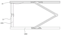
The bottom end of the sealing plate is connected with folding rods and rotating rings, fan blades are connected between the rotating rings and are opposite to openings at the bottom ends of the sinking and floating tubes, the folding rods are respectively and rotatably connected with the sealing plate and the rotating rings, the outer walls of the folding rods are connected with cleaning brushes, the cleaning brushes are attached to the inner walls of the sinking and floating tubes, and the outer walls of the sealing plate are provided with a plurality of groups of scraping grooves.
Through adopting above-mentioned technical scheme, can carry out abluent in-process to ups and downs bucket, the scraping groove through the closing plate outside clears up the ups and downs inside pipe wall, has improved cleaning efficiency.
In summary, the invention mainly has the following beneficial effects:
1. according to the invention, through the arrangement of the submerged bucket, the sinking and floating pipe and the water spraying disc, when sewage is aerated, the submerged bucket is firstly installed in the sewage, so that the submerged bucket floats on the sewage, at the moment, the sewage on the surface layer can pass through the filter plate and enter the blanking pipe, and finally enter the sinking and floating pipe, under the action of water pressure, the sewage is pressed into the water spraying disc, and the outer side of the water spraying disc is provided with a plurality of groups of inclined pipes, so that the sewage can be obliquely sprayed out, and the water spraying disc rotates under the reaction force of water flow, so that the sewage is driven to be rotationally sprayed out, the contact area of the sewage and air can be effectively increased, the aeration effect is improved, and the problem of poor aeration effect is effectively solved.
2. According to the invention, through the arrangement of the sinking and floating pipe, the weight of the sinking and floating pipe is increased after excessive impurities are in the sinking and floating pipe, the sinking and floating pipe moves downwards and extrudes the buffer mechanism until the bottom end of the sinking and floating pipe is in contact with the first sleeve ring, the first sleeve ring and the second sleeve ring are pushed to move downwards, the second sleeve ring drives the sealing block to be inserted into the jack to seal the drain pipe, the second sleeve ring is far away from the water suction port, so that the water pump is communicated with water in the submerged bucket, then the water pump is controlled through an electric control device to send water in the submerged bucket into the sinking and floating pipe, the water flow pushes the sealing plate to move upwards, the sealing plate scrapes off the inner wall of the sinking and floating pipe through the outer wall, a large amount of large-scale impurities are scraped off, the top end of the sinking and floating pipe is pushed to the top end through the water flow, the submerged personnel can drive the fan blades to rotate, the folding rods drive the folding rods to rotate, and the inner wall of the sinking and floating pipe is cleaned through the outer wall for the second time, so that the impurities can be cleaned effectively filtered and the impurities can be filtered.
Drawings
FIG. 1 is a schematic structural view of the present invention;
FIG. 2 is a schematic cross-sectional view of the present invention;
FIG. 3 is a schematic view of the floating bladder mounting structure of the present invention;
FIG. 4 is a schematic cross-sectional view of the floating plate of the present invention;
FIG. 5 is a schematic view of the structure of the water spraying plate of the present invention;
FIG. 6 is a schematic view of the seal plate structure of the present invention;
FIG. 7 is a schematic view of a swivel structure according to the present invention;
FIG. 8 is a schematic view of the cross-sectional structure of the water inlet of the present invention;
FIG. 9 is a schematic view of a buffering mechanism according to the present invention;
FIG. 10 is a schematic view of the electromagnet mounting structure of the present invention;
FIG. 11 is a schematic view of the inside structure of the drain pipe according to the present invention;
FIG. 12 is a schematic view of a fixing plate according to the present invention;
fig. 13 is a schematic view of the structure of the collar of the present invention.
In the figure: 1. submerging the barrel; 101. a filter plate; 102. an air inlet; 103. a discharging pipe; 104. a buffer seat; 105. an electromagnet; 2. a floating plate; 201. a solar panel; 202. a floating bag; 203. a storage battery; 3. sinking and floating pipes; 301. supporting legs; 302. a connecting rod; 4. a water pump; 401. a water inlet; 402. opening a hole; 5. a first collar; 501. a transmission rod; 502. a second collar; 503. a pressure lever; 504. a sealing block; 505. inserting a rod; 6. a drain pipe; 601. a fixing plate; 602. a jack; 603. a fixed block; 604. a water suction port; 7. a buffer mechanism; 701. a buffer spring; 8. a water spray disc; 801. an inclined tube; 802. grooving; 9. A wire; 10. a sealing plate; 1001. a folding bar; 1002. rotating the ring; 1003. a fan blade; 11. and (4) cleaning brushes.
Detailed Description
The technical solution in the embodiments of the present invention will be clearly and completely described below with reference to the accompanying drawings in the embodiments of the present invention. The embodiments described below with reference to the accompanying drawings are illustrative only for the purpose of explaining the present invention, and are not to be construed as limiting the present invention.
The following describes an embodiment of the present invention based on its overall structure.
An auxiliary device for improving microbial decomposition efficiency by automatic aeration for sewage treatment comprises a submerged bucket 1, a blanking pipe 103 is arranged at the top end of the submerged bucket 1, four groups of air inlets 102 are arranged around the blanking pipe 103, a floating plate 2 is arranged on the outer wall of each air inlet 102, a solar panel 201 and a storage battery 203 are arranged in the floating plate 2, the solar panel 201 is positioned at the top end of the floating plate 2, the storage battery 203 is positioned at the central position of the floating plate 2, the solar panel 201 is connected with the storage battery 203 through a connecting wire, a plurality of groups of floating capsules 202 are arranged at the bottom end of the floating plate 2 and positioned at two sides of the storage battery 203, the output end of the storage battery 203 is connected with a conducting wire 9, and the conducting wire 9 extends to the bottom end of the submerged bucket 1, when the device is used, the submerged bucket 1 is placed into water, and the submerged bucket 2 floats on sewage through the floating plate 2, the inner part of the blanking pipe 103 is provided with the sinking and floating pipe 3, the outer wall of the sinking and floating pipe 3 is provided with a plurality of groups of water spraying discs 8, the sinking and floating pipe 3 is positioned at the outer side of each group of water spraying discs 8 and is connected with a connecting rod 302, the inner wall of each water spraying disc 8 is provided with a slot 802, the slot 802 is communicated with the inner part of the sinking and floating pipe 3, the outer wall of each water spraying disc 8 is provided with a plurality of groups of inclined pipes 801, each group of inclined pipes 801 is communicated with the slot 802, after sewage enters the blanking pipe 103, the sewage continuously enters the sinking and floating pipe 3 to form a water column in the sinking and floating pipe 3, the pressure of the water column pushes the sinking and floating pipe 3 to move downwards, so that the sinking and floating pipe 3 extrudes a buffer spring 701 in a buffer mechanism 7, then the sewage is sprayed out from the plurality of groups of water spraying discs 8 arranged in the sinking and floating pipe 3, and the inner wall of each water spraying disc 8 is provided with a plurality of groups of inclined pipes 801, when the water flow is sprayed out, the water flow drives the water spraying discs 8 to rotate, thereby rotating the water spray disk 8 and driving the sprayed water to be sprayed in the diving barrel 1 in a rotating way, thereby effectively increasing the contact area of the sewage and the air and improving the oxygen content in the sewage;
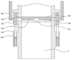
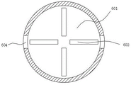
the bottom end of the sinking and floating pipe 3 is an opening, a sealing plate 10 is arranged above the opening in the sinking and floating pipe 3, a water pump 4 is arranged in the diving bucket 1 below the sealing plate 10, the water in the diving bucket 1 can be controlled through the water pump 4, excessive water in the diving bucket 1 is avoided, the bottom end of the sealing plate 10 is connected with a folding rod 1001 and a rotating ring 1002, a fan blade 1003 is connected between the rotating rings 1002, the fan blade 1003 is just opposite to the opening at the bottom end of the sinking and floating pipe 3, the folding rod is respectively and rotatably connected with the sealing plate 10 and the rotating ring 1002, the outer wall of the folding rod 1001 is connected with a cleaning brush 11, the cleaning brush 11 is attached to the inner wall of the sinking and floating pipe 3, a plurality of groups of scraping grooves are arranged on the outer wall of the sealing plate 10, the inner wall of the sinking and floating pipe 3 can be cleaned in the moving process of the sealing plate 10, an electric control mechanism is arranged on the outer wall of the water pump 4, the bottom end output end of the water pump 4 is connected with a drain pipe 6, the outer wall of the drain pipe 6 is provided with a plurality of groups of water suction ports 604, a fixing plate 601 is arranged in the drain pipe 6 below the water suction ports 604, a plurality of groups of jacks 602 are arranged on the inner wall of the fixing plate 601, a first lantern ring 5 is arranged on the outer side of the output end of the top end of the water pump 4, the output end of the upper end of the water pump 4 is connected with a water inlet 401, a plurality of groups of holes 402 are arranged on the outer wall of the water inlet 401, the holes 402 are arranged below the first lantern ring 5, the outer side of the first lantern ring 5 is connected with a transmission rod 501, a second lantern ring 502 is arranged on the outer wall of the drain pipe 6 outside the water suction ports 604, the first lantern ring 5 is in transmission connection with the second lantern ring 502 through the transmission rod 501, a fixing block 603 is arranged on the outer wall of the drain pipe 6, a plurality of springs are arranged in the fixing block 603, a plurality of groups of insert rods 505 are connected with the springs, the inner wall of the second lantern ring 502 is positioned in the water suction port 604 and provided with a pressure lever 503 extending to the inside of the water discharge pipe 6, the bottom end of the pressure lever 503 is connected with a sealing block 504 matched with the jack 602, the water discharge pipe 6 extends to the outside of the submerged bucket 1, impurities such as silt and the like can be continuously attached to the inside of the water spray disc 8 and the inner wall of the sinking and floating pipe 3, the impurities can continuously increase the gravity of the sinking and floating pipe 3, so that the sinking and floating pipe 3 can continuously descend until the bottom end of the sinking and floating pipe 3 is contacted with the first lantern ring 5, the sinking and floating pipe 3 pushes the first lantern ring 5 to move downwards, the first lantern ring 5 pushes the second lantern ring 502 to move downwards through the transmission rod 501, so as to drive the pressure lever 503 and the sealing block 504 to move downwards, so that the sealing block 504 is inserted into the jack 602 to seal the fixing plate 601, the second lantern ring 502 is far away from the water suction port 604, so that the water suction port 604 is opened, and at the same time, buffer gear 7 also is in continuous downstream, connecting wire and wire 9 switch-on in buffer gear 7, supply power to the electrical control equipment in electro-magnet 105 and the water pump 4 outside through the connecting wire, thereby change the output of water pump 4 when carrying on spacingly to the pipe 3 that floats, make the water in the dive bucket 1 enter into the pipe 3 that floats, closing plate 10 through rivers jack-up clears up the pipe 3 inner wall that floats, closing plate 10 can drive the rotatory expansion of multiunit folding rod 1001 when removing, and the outside of folding rod 1001 has seted up multiunit cleaning brush 11, and when rivers enter into the pipe 3 that floats, rivers can drive the flabellum and rotate, flabellum 1003 can drive swivel 1002 and scraper blade folding rod 1001 synchronous rotation, thereby make cleaning brush 11 can clear up the pipe 3 inner wall that floats, and cleaning brush 11 can carry out synchronous washing to the fluting 802 of the inner wall of spray disc 8.
Referring to fig. 1, the top end of the submerged bucket 1 is provided with a filter plate 101 between each group of blanking pipes 103, the air inlet 102 is communicated with the inside of the submerged bucket 1, and the blanking pipes 103 and the submerged pipe 3 are both positioned below the air inlet 102, so that large impurities in sewage can be filtered and removed through the filter plate 101, and the probability of the impurities blocking in the submerged pipe 3 is reduced.
Referring to fig. 9 to 10, the bottom end of the sinking-floating pipe 3 is provided with a plurality of sets of supporting legs 301 around the water pump 4, each set of supporting legs 301 extends to the inner wall of the submergence barrel 1 and is connected with a buffer mechanism 7, the inside of the buffer mechanism 7 is connected with a three-way connecting wire, the three-way connecting wire is matched with the wire 9, the inner wall of the bottom end of the submergence barrel 1 is provided with a buffer seat 104, the buffer mechanism 7 is located inside the buffer seat 104, the outer side of the buffer mechanism 7 is sleeved with a buffer spring 701, the outer wall of the buffer mechanism 7 is provided with a groove, the submergence barrel 1 is provided with an electromagnet 105 at one side of the buffer seat 104, the output end of the electromagnet 105 is matched with the groove, the outer side of the output end of the electromagnet 105 is also sleeved with a spring, the external wire of the electromagnet 105 is matched with one end of the three-way connecting wire, the sinking-floating pipe 3 can be limited through the electromagnet 105, and the sinking-floating pipe 3 is prevented from floating because impurities are removed in the cleaning process.
Referring to fig. 2, a water level sensor is installed on the inner wall of the submergence barrel 1 between the output end of the upper end of the water pump 4 and the bottom end of the submergence tube 3, and the water level sensor is connected with the storage battery 203 and the electric control mechanism through a wire 9, so that the water level in the submergence barrel 1 can be conveniently controlled, and the excessive water in the submergence barrel 1 is avoided.
The working principle of the invention is as follows: when the equipment is used, the equipment is firstly assembled, the second sleeve ring 502 is firstly installed on the outer side of the drain pipe 6, the inserting rod 505 is inserted into the inserting hole 602, the pressing rod 503 is placed into the drain pipe 6, the sealing block 504 can be inserted into the fixing block 603, the second sleeve ring 502 is limited by the spring, the pressing rod 503 is welded with the inner wall of the second sleeve ring 502 through the water suction port 604, the drain pipe 6 is installed on the output port of the water pump 4, the first sleeve ring 5 is installed on the water inlet 401 of the water pump 4, the first sleeve ring 5 and the second sleeve ring 502 are connected through the driving rod 501, the water pump 4 is installed inside the submerged bucket 1, the drain pipe 6 is inserted into the bottom end of the submerged bucket 1, the submerged pipe 3 is installed into the submerged bucket 103, the supporting feet 301 at the bottom end of the submerged pipe 3 are inserted into the buffering seat 104, the buffering mechanism 7 is installed into the buffering seat 104, then the groups of floating plates 2 are installed on the outer side of the filtering plates 101, the storage batteries are connected with the groups of the submerged bucket 1 through the conducting wires 9, the submerged bucket 1 can run, and the submerged bucket 1 can pass through the floating plates 2, and the submerged bucket 1, and the sewage can be placed on the submerged bucket 1 and the sewage can be placed on the submerged bucket 1;
when the device is used, the part of the filter plate 101 outside the submerged bucket 1 is positioned under sewage, so that sewage on the surface layer can pass through the filter plate 101 and reach the discharging pipe 103, the sewage falls into the sinking and floating pipe 3 under the action of gravity, so that a water column can be formed in the sinking and floating pipe 3, the pressure of the water column pushes the sinking and floating pipe 3 to move downwards, the sinking and floating pipe 3 extrudes the buffer spring 701 in the buffer mechanism 7, then the sewage is sprayed out from a plurality of groups of water spraying discs 8 arranged in the sinking and floating pipe 3, and a plurality of groups of inclined pipes 801 are arranged on the inner wall of each water spraying disc 8;
however, in the process of spraying sewage, impurities such as sludge and the like are continuously attached to the inside of the water spraying disc 8 and the inner wall of the sinking and floating pipe 3, the gravity of the sinking and floating pipe 3 is continuously increased by the impurities, so that the sinking and floating pipe 3 is also continuously descended until the bottom end of the sinking and floating pipe 3 is contacted with the first lantern ring 5, the sinking and floating pipe 3 pushes the first lantern ring 5 to move downwards, the first lantern ring 5 pushes the second lantern ring 502 to move downwards through the transmission rod 501, so that the compression rod 503 and the sealing block 504 are driven to move downwards, the sealing block 504 is inserted into the jack 602 to seal the fixing plate 601, the second lantern ring 502 is far away from the water suction port 604, so that the water suction port 604 is opened, meanwhile, the buffer mechanism 7 also continuously moves downwards, the connecting line in the buffer mechanism 7 is communicated with the lead wire 9, the connecting line is of a three-way type, one end is contacted with the electromagnet 105, so that the electromagnet 105 is powered on and started, the output end of the electromagnet 105 is inserted into a groove formed in the inner wall of the buffer mechanism 7 to limit the buffer mechanism 7, the other end of the three-way connecting line is connected with a control device for controlling the water pump 4, a power signal transmitted by a lead 9 is connected into the electric control device, the electric control device controls the water pump 4 to enable the water pump 4 to run reversely, the water pump 4 sucks water treated in the submergence barrel 1 into the water pump 4 through a water suction port 604 and sends the water into the submergence tube 3 through a water inlet 401, water flow jacks up a sealing plate 10 in the submergence tube 3 to enable the sealing plate 10 to move upwards, the sealing plate 10 can scrape the inner wall of the submergence tube 3 during moving, jack up large impurities, convey the large impurities to an opening at the top end of the submergence tube 3 and clean the impurities through outside personnel, and the sealing plate 10 pushes outside sewage to move upwards in the submergence tube 3, it can avoid sewage still to pile up in submarine bucket 1 inner wall outside, sealing plate 10 can drive the rotatory expansion of multiunit folding rod 1001 when removing, and the multiunit cleaning brush 11 has been seted up to the outside of folding rod 1001, and when rivers entered into ups and downs pipe 3 in, rivers can drive flabellum 1003 and rotate, flabellum 1003 can drive swivel 1002 and scraper blade folding rod 1001 synchronous rotation, thereby make cleaning brush 11 can clear up the inner wall of ups and downs pipe 3, and cleaning brush 11 can wash the fluting 802 of water spray disc 8 inner wall in step, wash a period of time after, reverse start water pump 4 once more, make water pump 4 take out the washing water in the ups and downs pipe 3, make sealing plate 10 return, wash water returns in submarine bucket 1, the power supply to water pump 4 and electro-magnet 105 is cut off this moment, electro-magnet 105 is under the promotion of the outside the output side spring, electro-magnet 105 output side removes the spacing to electro-magnet 301, this moment, the inside accumulational impurity of pipe 3 that floats reduces in a large amount, buffer gear 7 can promote ups and floats pipe 3 and returns the normal position, make sunken pipe 3 not extrude first lantern ring 5 and second lantern ring 5 and take out, thereby the efficiency of the sealed thimble of the sealed submarine bucket is improved and the sealed in the sealed thimble 602 that the sealed water pump can be taken out, thereby the normal use the sealed equipment, thereby the efficiency of the sealed thimble is reduced.
Although embodiments of this invention have been shown and described, it is to be understood that such embodiments are merely illustrative of and not restrictive on the broad invention, and that any one or more of the described features, structures, materials, or characteristics may be combined in any suitable manner in any one or more embodiments or examples, and that modifications, substitutions, and variations that do not materially contribute to the novel teachings of this invention may be made by those skilled in the art after reading this disclosure without departing from the principles and spirit of this invention, but within the scope of the appended claims.
Claims (4)
1. The utility model provides a sewage treatment improves auxiliary assembly of microbial decomposition efficiency with automatic aeration, includes dive bucket (1), its characterized in that: the top end of the submerged bucket (1) is provided with a discharging pipe (103), four groups of air inlets (102) are arranged around the periphery of the discharging pipe (103), the outer wall of each group of air inlets (102) is provided with a floating plate (2), a solar panel (201) and a storage battery (203) are arranged inside the floating plate (2), the output end of the storage battery (203) is connected with a lead (9), the lead (9) extends to the bottom end of the submerged bucket (1), a sinking and floating pipe (3) is arranged inside the discharging pipe (103), a plurality of groups of water spraying discs (8) are arranged on the outer wall of the sinking and floating pipe (3), the bottom end of the sinking and floating pipe (3) is an opening, a sealing plate (10) is arranged above the opening inside of the sinking and floating pipe (3), a water pump (4) is arranged inside the submerged bucket (1) below the sealing plate (10), an electric control mechanism is arranged on the outer wall of the water pump (4), the bottom end output end of the water pump (4) is connected with a drain pipe (6), a plurality of groups of water absorbing openings (604) are arranged on the outer side of the submerged bucket (1), a plurality of water absorbing openings (601), and a plurality of water absorbing openings (601) are arranged on the outer side of the inner wall of the water absorbing ring (601), and a plurality of the water absorbing ring (601) is arranged on the fixing plate (601), a second sleeve ring (502) is mounted on the outer wall of the drain pipe (6) and located on the outer side of the water suction port (604), a pressure rod (503) extending into the drain pipe (6) is arranged on the inner wall of the second sleeve ring (502) and located in the water suction port (604), a sealing block (504) matched with the insertion hole (602) is connected to the bottom end of the pressure rod (503), and the drain pipe (6) extends to the outer side of the submerged barrel (1);
the bottom end of the sinking-floating pipe (3) is provided with a plurality of groups of supporting legs (301) around the water pump (4), the inner wall of each group of supporting legs (301) extending to the submergence barrel (1) is connected with a buffer mechanism (7), the inside of the buffer mechanism (7) is connected with a three-way connecting line, the three-way connecting line is matched with a lead (9), the inner wall of the bottom end of the submergence barrel (1) is provided with a buffer seat (104), the buffer mechanism (7) is positioned inside the buffer seat (104), the outer side of the buffer mechanism (7) is sleeved with a buffer spring (701) in a surrounding manner, and the outer wall of the buffer mechanism (7) is provided with a groove;
an electromagnet (105) is installed on one side, located on the buffer seat (104), of the submergence barrel (1), the output end of the electromagnet (105) is matched with the groove, a spring is sleeved on the outer side of the output end of the electromagnet (105), and an external lead of the electromagnet (105) is matched with one end of a three-way connecting wire;
the water pump is characterized in that an output end at the upper end of the water pump (4) is connected with a water inlet (401), the outer wall of the water inlet (401) is provided with a plurality of groups of open holes (402), the open holes (402) are located below a first sleeve ring (5), the outer side of the first sleeve ring (5) is connected with a transmission rod (501), the first sleeve ring (5) is in transmission connection with a second sleeve ring (502) through the transmission rod (501), the outer wall of the drain pipe (6) is provided with a fixed block (603), a plurality of groups of springs are arranged inside the fixed block (603), the bottom end of the second sleeve ring (502) is connected with a plurality of groups of insertion rods (505), and each group of insertion rods (505) extends into the fixed block (603) and is connected with the springs;
the sinking and floating pipe (3) is positioned at the outer side of each group of water spraying discs (8) and is connected with a connecting rod (302), the inner wall of each water spraying disc (8) is provided with a notch (802), the notch (802) is communicated with the inside of the sinking and floating pipe (3), the outer wall of each water spraying disc (8) is provided with a plurality of groups of inclined pipes (801), and each group of inclined pipes (801) is communicated with the notch (802);
the bottom of closing plate (10) is connected with folding rod (1001) and change (1002), be connected with flabellum (1003) between change (1002), and flabellum (1003) just to sinking the opening that floats pipe (3) bottom, and folding rod (1001) rotate with closing plate (10) and change (1002) respectively and be connected, the outer wall connection of folding rod (1001) has cleaning brush (11), and cleaning brush (11) and the inner wall laminating that floats pipe (3), the multiunit groove of scraping has been seted up to the outer wall of closing plate (10).
2. The auxiliary equipment for improving the decomposition efficiency of microorganisms through automatic aeration according to claim 1, which is characterized in that: the top of the submerged bucket (1) is located and all installs filter plate (101) between every group unloading pipe (103), air inlet (102) and the inside switch-on of submerged bucket (1), and unloading pipe (103) and sink and float pipe (3) and all are located the below of air inlet (102).
3. The auxiliary equipment for improving the decomposition efficiency of microorganisms through automatic aeration according to claim 1, which is characterized in that: solar panel (201) are located the top of floating board (2), battery (203) are located the central point who floats board (2) and put, and solar panel (201) are connected through the connecting wire with battery (203), the bottom that floats board (2) is located battery (203) both sides and all installs multiunit floating bag (202).
4. The auxiliary equipment for improving the decomposition efficiency of microorganisms through automatic aeration according to claim 1, which is characterized in that: a water level sensor is arranged on the inner wall of the submersible barrel (1) and between the output end of the upper end of the water pump (4) and the bottom end of the sinking and floating pipe (3), and the water level sensor is connected with the storage battery (203) and the electric control mechanism through a lead (9).
Priority Applications (1)
| Application Number | Priority Date | Filing Date | Title |
|---|---|---|---|
| CN202210184723.6A CN114436478B (en) | 2022-02-28 | 2022-02-28 | Auxiliary assembly for improving microbial decomposition efficiency by automatic aeration for sewage treatment |
Applications Claiming Priority (1)
| Application Number | Priority Date | Filing Date | Title |
|---|---|---|---|
| CN202210184723.6A CN114436478B (en) | 2022-02-28 | 2022-02-28 | Auxiliary assembly for improving microbial decomposition efficiency by automatic aeration for sewage treatment |
Publications (2)
| Publication Number | Publication Date |
|---|---|
| CN114436478A CN114436478A (en) | 2022-05-06 |
| CN114436478B true CN114436478B (en) | 2022-11-25 |
Family
ID=81373795
Family Applications (1)
| Application Number | Title | Priority Date | Filing Date |
|---|---|---|---|
| CN202210184723.6A Active CN114436478B (en) | 2022-02-28 | 2022-02-28 | Auxiliary assembly for improving microbial decomposition efficiency by automatic aeration for sewage treatment |
Country Status (1)
| Country | Link |
|---|---|
| CN (1) | CN114436478B (en) |
Families Citing this family (2)
| Publication number | Priority date | Publication date | Assignee | Title |
|---|---|---|---|---|
| CN116140306B (en) * | 2023-03-09 | 2026-02-17 | 沧州水利勘测规划设计院有限公司 | A type of pipeline dredging equipment for water conservancy projects |
| CN118304736B (en) * | 2024-06-11 | 2024-08-16 | 四川省阳子森环保设备有限公司 | Indoor dust reducing device for building construction and application method thereof |
Citations (3)
| Publication number | Priority date | Publication date | Assignee | Title |
|---|---|---|---|---|
| CN212864264U (en) * | 2020-08-13 | 2021-04-02 | 章万喜 | A sewage treatment device for jet aeration biological reaction |
| CN112979069A (en) * | 2021-02-23 | 2021-06-18 | 广西盛唯科技服务有限公司 | Multi-level efficient sewage treatment aeration equipment |
| CN215886443U (en) * | 2021-08-11 | 2022-02-22 | 沈阳水清环境工程有限公司 | High-efficient air supporting water treatment facilities |
-
2022
- 2022-02-28 CN CN202210184723.6A patent/CN114436478B/en active Active
Patent Citations (3)
| Publication number | Priority date | Publication date | Assignee | Title |
|---|---|---|---|---|
| CN212864264U (en) * | 2020-08-13 | 2021-04-02 | 章万喜 | A sewage treatment device for jet aeration biological reaction |
| CN112979069A (en) * | 2021-02-23 | 2021-06-18 | 广西盛唯科技服务有限公司 | Multi-level efficient sewage treatment aeration equipment |
| CN215886443U (en) * | 2021-08-11 | 2022-02-22 | 沈阳水清环境工程有限公司 | High-efficient air supporting water treatment facilities |
Also Published As
| Publication number | Publication date |
|---|---|
| CN114436478A (en) | 2022-05-06 |
Similar Documents
| Publication | Publication Date | Title |
|---|---|---|
| CN114436478A (en) | Auxiliary assembly for improving microbial decomposition efficiency by automatic aeration for sewage treatment | |
| CN112320932A (en) | Hollow plate type ceramic membrane bioreactor and wastewater treatment method | |
| CN102258944B (en) | Online cleaning method for membrane-bioreactor | |
| CN103331103B (en) | Novel high-efficiency flexible flat sheet membrane on-line automatic physical cleaning device | |
| CN104727365B (en) | Solar energy underwater dirt suction device | |
| CN116924561B (en) | Household garbage wastewater treatment equipment and method | |
| CN216155693U (en) | New energy distributed domestic sewage purification device | |
| CN209442676U (en) | A kind of float type water Environmental Chemistry clarifier-tank | |
| CN1548389A (en) | Household intermediate water processing machine | |
| CN219058636U (en) | Electrochemical water treatment tank with high treatment efficiency | |
| CN114651715B (en) | Greening type landscape building capable of improving water body | |
| CN206940687U (en) | A kind of energy-saving water purifying device | |
| CN206901989U (en) | A kind of high efficiency sewage disposal system device | |
| CN110122406A (en) | A kind of molecular level oxygen-increasing device based on electrolysis and hydrogen fuel cell energy regenerating | |
| CN118058223A (en) | Rotatory dirt collection oxygenation of living body bait characteristic breeds integrated equipment | |
| CN215667612U (en) | Biochemical sewage treatment device of integration | |
| CN218371955U (en) | Biofilm reactor that treatment effeciency is high | |
| CN115432783A (en) | A wastewater electrocatalytic oxidation reactor | |
| CN215799053U (en) | Device suitable for rural sewage high-efficiency treatment in yellow river basin | |
| CN207877506U (en) | A kind of integrated sewage disposal pond | |
| CN108083421B (en) | Energy-saving sewage treatment device and system | |
| CN217077078U (en) | Electrolytic dephosphorization equipment for sewage treatment | |
| CN216737746U (en) | Anaerobic reactor with sludge removal structure | |
| CN213387987U (en) | Self-cleaning beneficial bacterium bed | |
| CN219950715U (en) | Energy-saving environment-friendly microbial sewage treatment device |
Legal Events
| Date | Code | Title | Description |
|---|---|---|---|
| PB01 | Publication | ||
| PB01 | Publication | ||
| SE01 | Entry into force of request for substantive examination | ||
| SE01 | Entry into force of request for substantive examination | ||
| GR01 | Patent grant | ||
| GR01 | Patent grant |