CN114414074B - Cantilever type intelligent temperature measurement and detection device for vertical shaft - Google Patents
Cantilever type intelligent temperature measurement and detection device for vertical shaft Download PDFInfo
- Publication number
- CN114414074B CN114414074B CN202210336081.7A CN202210336081A CN114414074B CN 114414074 B CN114414074 B CN 114414074B CN 202210336081 A CN202210336081 A CN 202210336081A CN 114414074 B CN114414074 B CN 114414074B
- Authority
- CN
- China
- Prior art keywords
- temperature measurement
- traction
- cantilever
- hydraulic cylinder
- shaft
- Prior art date
- Legal status (The legal status is an assumption and is not a legal conclusion. Google has not performed a legal analysis and makes no representation as to the accuracy of the status listed.)
- Active
Links
- 238000001514 detection method Methods 0.000 title claims abstract description 133
- 238000009529 body temperature measurement Methods 0.000 title claims abstract description 103
- 230000009194 climbing Effects 0.000 claims description 74
- 238000005259 measurement Methods 0.000 description 13
- 238000012360 testing method Methods 0.000 description 11
- 229910000831 Steel Inorganic materials 0.000 description 7
- 239000010959 steel Substances 0.000 description 7
- 238000000034 method Methods 0.000 description 6
- 239000000725 suspension Substances 0.000 description 6
- 125000003003 spiro group Chemical group 0.000 description 5
- 230000008569 process Effects 0.000 description 4
- 239000011435 rock Substances 0.000 description 4
- XLYOFNOQVPJJNP-UHFFFAOYSA-N water Substances O XLYOFNOQVPJJNP-UHFFFAOYSA-N 0.000 description 4
- 230000008859 change Effects 0.000 description 2
- 238000010276 construction Methods 0.000 description 2
- 230000008602 contraction Effects 0.000 description 2
- 230000005484 gravity Effects 0.000 description 2
- 238000009434 installation Methods 0.000 description 2
- 230000004048 modification Effects 0.000 description 2
- 238000012986 modification Methods 0.000 description 2
- 230000002093 peripheral effect Effects 0.000 description 2
- 230000003014 reinforcing effect Effects 0.000 description 2
- 230000008054 signal transmission Effects 0.000 description 2
- 230000017105 transposition Effects 0.000 description 2
- 230000009286 beneficial effect Effects 0.000 description 1
- 238000004364 calculation method Methods 0.000 description 1
- 238000013461 design Methods 0.000 description 1
- 230000006872 improvement Effects 0.000 description 1
- 230000001788 irregular Effects 0.000 description 1
- 238000010030 laminating Methods 0.000 description 1
- 239000000203 mixture Substances 0.000 description 1
- 239000002893 slag Substances 0.000 description 1
- 230000006641 stabilisation Effects 0.000 description 1
- 238000011105 stabilization Methods 0.000 description 1
- 238000009423 ventilation Methods 0.000 description 1
Images



Classifications
-
- G—PHYSICS
- G01—MEASURING; TESTING
- G01K—MEASURING TEMPERATURE; MEASURING QUANTITY OF HEAT; THERMALLY-SENSITIVE ELEMENTS NOT OTHERWISE PROVIDED FOR
- G01K1/00—Details of thermometers not specially adapted for particular types of thermometer
- G01K1/14—Supports; Fastening devices; Arrangements for mounting thermometers in particular locations
-
- B—PERFORMING OPERATIONS; TRANSPORTING
- B66—HOISTING; LIFTING; HAULING
- B66D—CAPSTANS; WINCHES; TACKLES, e.g. PULLEY BLOCKS; HOISTS
- B66D1/00—Rope, cable, or chain winding mechanisms; Capstans
- B66D1/60—Rope, cable, or chain winding mechanisms; Capstans adapted for special purposes
- B66D1/74—Capstans
- B66D1/7405—Capstans having two or more drums providing tractive force
-
- B—PERFORMING OPERATIONS; TRANSPORTING
- B66—HOISTING; LIFTING; HAULING
- B66D—CAPSTANS; WINCHES; TACKLES, e.g. PULLEY BLOCKS; HOISTS
- B66D1/00—Rope, cable, or chain winding mechanisms; Capstans
- B66D1/60—Rope, cable, or chain winding mechanisms; Capstans adapted for special purposes
- B66D1/74—Capstans
- B66D1/7442—Capstans having a horizontal rotation axis
- B66D1/7447—Capstans having a horizontal rotation axis driven by motor only
-
- F—MECHANICAL ENGINEERING; LIGHTING; HEATING; WEAPONS; BLASTING
- F16—ENGINEERING ELEMENTS AND UNITS; GENERAL MEASURES FOR PRODUCING AND MAINTAINING EFFECTIVE FUNCTIONING OF MACHINES OR INSTALLATIONS; THERMAL INSULATION IN GENERAL
- F16M—FRAMES, CASINGS OR BEDS OF ENGINES, MACHINES OR APPARATUS, NOT SPECIFIC TO ENGINES, MACHINES OR APPARATUS PROVIDED FOR ELSEWHERE; STANDS; SUPPORTS
- F16M11/00—Stands or trestles as supports for apparatus or articles placed thereon ; Stands for scientific apparatus such as gravitational force meters
- F16M11/02—Heads
- F16M11/04—Means for attachment of apparatus; Means allowing adjustment of the apparatus relatively to the stand
- F16M11/043—Allowing translations
- F16M11/046—Allowing translations adapted to upward-downward translation movement
-
- F—MECHANICAL ENGINEERING; LIGHTING; HEATING; WEAPONS; BLASTING
- F16—ENGINEERING ELEMENTS AND UNITS; GENERAL MEASURES FOR PRODUCING AND MAINTAINING EFFECTIVE FUNCTIONING OF MACHINES OR INSTALLATIONS; THERMAL INSULATION IN GENERAL
- F16M—FRAMES, CASINGS OR BEDS OF ENGINES, MACHINES OR APPARATUS, NOT SPECIFIC TO ENGINES, MACHINES OR APPARATUS PROVIDED FOR ELSEWHERE; STANDS; SUPPORTS
- F16M11/00—Stands or trestles as supports for apparatus or articles placed thereon ; Stands for scientific apparatus such as gravitational force meters
- F16M11/02—Heads
- F16M11/04—Means for attachment of apparatus; Means allowing adjustment of the apparatus relatively to the stand
- F16M11/06—Means for attachment of apparatus; Means allowing adjustment of the apparatus relatively to the stand allowing pivoting
- F16M11/08—Means for attachment of apparatus; Means allowing adjustment of the apparatus relatively to the stand allowing pivoting around a vertical axis, e.g. panoramic heads
-
- F—MECHANICAL ENGINEERING; LIGHTING; HEATING; WEAPONS; BLASTING
- F16—ENGINEERING ELEMENTS AND UNITS; GENERAL MEASURES FOR PRODUCING AND MAINTAINING EFFECTIVE FUNCTIONING OF MACHINES OR INSTALLATIONS; THERMAL INSULATION IN GENERAL
- F16M—FRAMES, CASINGS OR BEDS OF ENGINES, MACHINES OR APPARATUS, NOT SPECIFIC TO ENGINES, MACHINES OR APPARATUS PROVIDED FOR ELSEWHERE; STANDS; SUPPORTS
- F16M11/00—Stands or trestles as supports for apparatus or articles placed thereon ; Stands for scientific apparatus such as gravitational force meters
- F16M11/02—Heads
- F16M11/18—Heads with mechanism for moving the apparatus relatively to the stand
-
- F—MECHANICAL ENGINEERING; LIGHTING; HEATING; WEAPONS; BLASTING
- F16—ENGINEERING ELEMENTS AND UNITS; GENERAL MEASURES FOR PRODUCING AND MAINTAINING EFFECTIVE FUNCTIONING OF MACHINES OR INSTALLATIONS; THERMAL INSULATION IN GENERAL
- F16M—FRAMES, CASINGS OR BEDS OF ENGINES, MACHINES OR APPARATUS, NOT SPECIFIC TO ENGINES, MACHINES OR APPARATUS PROVIDED FOR ELSEWHERE; STANDS; SUPPORTS
- F16M11/00—Stands or trestles as supports for apparatus or articles placed thereon ; Stands for scientific apparatus such as gravitational force meters
- F16M11/20—Undercarriages with or without wheels
- F16M11/2007—Undercarriages with or without wheels comprising means allowing pivoting adjustment
- F16M11/2035—Undercarriages with or without wheels comprising means allowing pivoting adjustment in more than one direction
-
- F—MECHANICAL ENGINEERING; LIGHTING; HEATING; WEAPONS; BLASTING
- F16—ENGINEERING ELEMENTS AND UNITS; GENERAL MEASURES FOR PRODUCING AND MAINTAINING EFFECTIVE FUNCTIONING OF MACHINES OR INSTALLATIONS; THERMAL INSULATION IN GENERAL
- F16M—FRAMES, CASINGS OR BEDS OF ENGINES, MACHINES OR APPARATUS, NOT SPECIFIC TO ENGINES, MACHINES OR APPARATUS PROVIDED FOR ELSEWHERE; STANDS; SUPPORTS
- F16M11/00—Stands or trestles as supports for apparatus or articles placed thereon ; Stands for scientific apparatus such as gravitational force meters
- F16M11/20—Undercarriages with or without wheels
- F16M11/2092—Undercarriages with or without wheels comprising means allowing depth adjustment, i.e. forward-backward translation of the head relatively to the undercarriage
-
- F—MECHANICAL ENGINEERING; LIGHTING; HEATING; WEAPONS; BLASTING
- F16—ENGINEERING ELEMENTS AND UNITS; GENERAL MEASURES FOR PRODUCING AND MAINTAINING EFFECTIVE FUNCTIONING OF MACHINES OR INSTALLATIONS; THERMAL INSULATION IN GENERAL
- F16M—FRAMES, CASINGS OR BEDS OF ENGINES, MACHINES OR APPARATUS, NOT SPECIFIC TO ENGINES, MACHINES OR APPARATUS PROVIDED FOR ELSEWHERE; STANDS; SUPPORTS
- F16M11/00—Stands or trestles as supports for apparatus or articles placed thereon ; Stands for scientific apparatus such as gravitational force meters
- F16M11/20—Undercarriages with or without wheels
- F16M11/24—Undercarriages with or without wheels changeable in height or length of legs, also for transport only, e.g. by means of tubes screwed into each other
-
- G—PHYSICS
- G01—MEASURING; TESTING
- G01K—MEASURING TEMPERATURE; MEASURING QUANTITY OF HEAT; THERMALLY-SENSITIVE ELEMENTS NOT OTHERWISE PROVIDED FOR
- G01K1/00—Details of thermometers not specially adapted for particular types of thermometer
- G01K1/14—Supports; Fastening devices; Arrangements for mounting thermometers in particular locations
- G01K1/146—Supports; Fastening devices; Arrangements for mounting thermometers in particular locations arrangements for moving thermometers to or from a measuring position
-
- G—PHYSICS
- G01—MEASURING; TESTING
- G01K—MEASURING TEMPERATURE; MEASURING QUANTITY OF HEAT; THERMALLY-SENSITIVE ELEMENTS NOT OTHERWISE PROVIDED FOR
- G01K13/00—Thermometers specially adapted for specific purposes
-
- F—MECHANICAL ENGINEERING; LIGHTING; HEATING; WEAPONS; BLASTING
- F16—ENGINEERING ELEMENTS AND UNITS; GENERAL MEASURES FOR PRODUCING AND MAINTAINING EFFECTIVE FUNCTIONING OF MACHINES OR INSTALLATIONS; THERMAL INSULATION IN GENERAL
- F16M—FRAMES, CASINGS OR BEDS OF ENGINES, MACHINES OR APPARATUS, NOT SPECIFIC TO ENGINES, MACHINES OR APPARATUS PROVIDED FOR ELSEWHERE; STANDS; SUPPORTS
- F16M2200/00—Details of stands or supports
- F16M2200/04—Balancing means
-
- F—MECHANICAL ENGINEERING; LIGHTING; HEATING; WEAPONS; BLASTING
- F16—ENGINEERING ELEMENTS AND UNITS; GENERAL MEASURES FOR PRODUCING AND MAINTAINING EFFECTIVE FUNCTIONING OF MACHINES OR INSTALLATIONS; THERMAL INSULATION IN GENERAL
- F16M—FRAMES, CASINGS OR BEDS OF ENGINES, MACHINES OR APPARATUS, NOT SPECIFIC TO ENGINES, MACHINES OR APPARATUS PROVIDED FOR ELSEWHERE; STANDS; SUPPORTS
- F16M2200/00—Details of stands or supports
- F16M2200/08—Foot or support base
-
- Y—GENERAL TAGGING OF NEW TECHNOLOGICAL DEVELOPMENTS; GENERAL TAGGING OF CROSS-SECTIONAL TECHNOLOGIES SPANNING OVER SEVERAL SECTIONS OF THE IPC; TECHNICAL SUBJECTS COVERED BY FORMER USPC CROSS-REFERENCE ART COLLECTIONS [XRACs] AND DIGESTS
- Y02—TECHNOLOGIES OR APPLICATIONS FOR MITIGATION OR ADAPTATION AGAINST CLIMATE CHANGE
- Y02E—REDUCTION OF GREENHOUSE GAS [GHG] EMISSIONS, RELATED TO ENERGY GENERATION, TRANSMISSION OR DISTRIBUTION
- Y02E10/00—Energy generation through renewable energy sources
- Y02E10/10—Geothermal energy
Landscapes
- Engineering & Computer Science (AREA)
- General Engineering & Computer Science (AREA)
- Mechanical Engineering (AREA)
- Physics & Mathematics (AREA)
- General Physics & Mathematics (AREA)
- Testing Or Calibration Of Command Recording Devices (AREA)
Abstract
The application provides a cantilever type intelligence temperature measurement detection device for shaft belongs to shaft temperature measurement technical field, and this cantilever type intelligence temperature measurement detection device for shaft includes balanced removal subassembly and cantilever locating component. The balance moving assembly comprises a moving frame, a balance side column, a side column hydraulic cylinder, a main vertical supporting column and a main vertical hydraulic cylinder, and the cantilever positioning assembly comprises a rotary column, a rotary motor, a cantilever sleeve, a positioning arm and a positioning hydraulic cylinder. The location pneumatic cylinder control location arm is at the telescopic slip centre gripping of cantilever, realize that temperature measurement detection device detects the regulation in the accurate stable support of shaft cross-section optional position and the long-range temperature measurement in the pit of high-efficient safety and stability, long-range cantilever supports, it faces the geological risk on limit to have reduced temperature measurement detection device ground fixed position in the shaft, it is flexible with hydraulic pressure slip through the motor rotation, the accurate detection position of adjusting temperature measurement detection device at the shaft, shaft intelligence temperature measurement safety and stability is high, shaft intelligence temperature measurement is more convenient.
Description
Technical Field
The application relates to the technical field of shaft temperature measurement, particularly, relate to a cantilever type intelligence temperature measurement detection device for shaft.
Background
The vertical shaft is a well-shaped pipeline with an upright hole wall, and is actually a collapsing funnel. The plane outline is square, long strip or irregular round. The well wall is steep and nearly vertical. The vertical shaft is widely applied to water taking, water diversion, ventilation and air exhaust, slag sliding and air supply of water conservancy and hydropower engineering, and the vertical shaft construction has the characteristics of small occupied area, less interference on peripheral construction and the like. The influence of the ground temperature heat damage on the vertical shaft is avoided by measuring the ground temperature gradient, the temperature abnormity of local rock strata and the temperature of the underground river caused by the depth change of the vertical shaft. Usually install temperature measuring device in steel wire one end, hang the vertical lift of steel wire control temperature measuring device through well head support, measure shaft inner wall temperature through temperature measuring device.
However, the shaft faces the limit and has the danger of collapsing, and current shaft temperature detects the operation and needs face the limit at the shaft and carry out the operation, hangs the vertical lift of steel wire control temperature measuring device through the well head support, when shaft well head geology sinks, causes the incident of measurement personnel and check out test set easily, and the safety risk of shaft temperature measurement is very outstanding.
Disclosure of Invention
The present application is directed to solving at least one of the problems in the prior art. For this, this application provides a cantilever type intelligence temperature measurement detection device for shaft lets detection device keep away from dangerous shaft through the cantilever and faces the limit, keeps detection device's balanced stable through hydraulic pressure, rotates through the flexible cooperation motor of hydraulic pressure, adjusts detection device's temperature measurement point, and shaft intelligence temperature measurement safety and stability is high, and shaft intelligence temperature measurement is more convenient.
The application is realized as follows:
the application provides a cantilever type intelligence temperature measurement detection device for shaft includes balanced removal subassembly and cantilever locating component.
The balance moving assembly comprises a moving frame, a balance side column, a side column hydraulic cylinder, a main vertical support column and a main vertical hydraulic cylinder, the balance side column is symmetrically and rotatably connected to the periphery of the moving frame, the cylinder body of the side column hydraulic cylinder is symmetrically and rotatably connected to the periphery of the moving frame, one end of the piston rod of the side column hydraulic cylinder is rotatably connected to the balance side column, one end of the main vertical support column is symmetrically and rotatably connected to the inside of the moving frame, the cylinder body of the main vertical hydraulic cylinder is symmetrically and rotatably connected to the inside of the moving frame, one end of the piston rod of the main vertical hydraulic cylinder is rotatably connected to the main vertical support column, the cantilever positioning assembly comprises a rotary column, a rotary motor, a cantilever sleeve, a positioning arm and a positioning hydraulic cylinder, the lower end of the rotary column is rotatably connected to the main vertical support column, the body of the rotary motor is arranged on the main vertical support column, and the output end of the rotary motor is meshed with the lower end of the main vertical support column, one end of the cantilever sleeve is arranged on the rotary column, one end of the positioning arm penetrates through the cantilever sleeve in a sliding mode, the cylinder body of the positioning hydraulic cylinder is arranged on the cantilever sleeve, and one end of the piston rod of the positioning hydraulic cylinder is fixed to the other end of the positioning arm.
In one embodiment of the present application, a fluted disc is fixedly sleeved on the lower end of the rotary column, and a gear is fixed on the output end of the rotary motor and is meshed with the fluted disc.
In one embodiment of the application, the top of the main vertical supporting column is provided with a rotary table, the lower end of the rotary column rotates in the rotary table, and the body of the rotary motor is provided with a mounting seat which is fixed on the rotary table.
In one embodiment of the present application, a first rotating seat is rotatably disposed at a lower end of the main upright support column, the first rotating seat is fixed in the moving frame, and a cylinder body of the main upright hydraulic cylinder is rotatably connected in the first rotating seat.
In an embodiment of the application, the upper end of the balance side column is rotatably provided with a second rotating seat, the second rotating seat is fixed on the moving frame, and the cylinder body of the side column hydraulic cylinder is rotatably connected in the second rotating seat.
In an embodiment of this application, removal frame one end is provided with the traction frame, it is provided with the walking wheel to remove frame lower extreme symmetry rotation.
In an embodiment of the present application, a first rotating shaft is disposed at one end of a piston rod of the main vertical hydraulic cylinder, and two ends of the first rotating shaft rotate in the main vertical supporting column.
In an embodiment of the present application, a second rotating shaft is disposed at one end of a piston rod of the side column hydraulic cylinder, and two ends of the second rotating shaft rotate in the balance side column.
In an embodiment of the present application, a cantilever table is disposed on the top of the rotating column, and one end of the cantilever sleeve is fixed in the cantilever table.
In an embodiment of the application, the positioning hydraulic cylinder body is provided with a pipe hoop, the pipe hoop is fixed on the cantilever sleeve, one end of the piston rod of the positioning hydraulic cylinder is provided with a positioning seat, and the positioning seat is fixed on the positioning arm.
In an embodiment of the application, the cantilever type intelligent temperature measurement and detection device for the vertical shaft further comprises a traction guide assembly, a climbing balance assembly and a detection balance assembly.
The traction guide assembly comprises a traction table, a traction roller, a traction motor, a guide seat and a traction rope, wherein the traction table is hung at the other end of the positioning arm, the traction roller symmetrically rotates on the traction table, the body of the traction motor is symmetrically arranged on the traction table, the output end of the traction motor is transmitted to the traction roller, the guide seat is symmetrically hung at the bottom of the traction table, the upper end of the traction rope is wound on the surface of the traction roller, the lower end of the traction rope slides in the guide seat, the climbing balance assembly comprises a climbing ring frame, an adjusting seat, an adjusting hydraulic cylinder, a roller frame, a first connecting rod, a second connecting rod, a climbing wheel and a climbing motor, the climbing ring frame is sleeved on the surface of the traction rope, the adjusting seat slides in the climbing ring frame symmetrically, the cylinder body of the adjusting hydraulic cylinder is symmetrically arranged on the climbing ring frame, one end of a piston rod of the adjusting hydraulic cylinder is fixed on the adjusting seat, the roller frames are symmetrically arranged in the climbing ring frame, one end of a first connecting rod is rotationally connected to the climbing ring frame, the other end of the first connecting rod is rotationally connected to the roller frame, one end of a second connecting rod is rotationally connected to the adjusting seat, the other end of the second connecting rod is rotationally connected to the roller frame, the climbing wheel is rotationally arranged in the roller frame, a body of the climbing motor is arranged on the roller frame, the output end of the climbing motor is driven to the climbing wheel, the detection balancing component comprises a detection table, a distance measuring module, a detection motor, a distribution disc and a detection main body, the detection table is arranged at the bottom of the climbing ring frame, the distance measuring module is uniformly arranged on the detection table, the distance measuring module faces to the other detection table, and the body of the detection motor is arranged at the center of the top of the detection table, the distribution disc is fixed on the output end of the detection motor, and the detection main body is uniformly arranged on the periphery of the distribution disc.
In an embodiment of this application, the symmetry is rotated and is provided with the leading wheel in the guide holder, the haulage rope slide run through in between the leading wheel, the haulage rope lower extreme is provided with the gravity ball.
In an embodiment of this application, the symmetry is provided with the seat of pulling on pulling the platform, pull the cylinder both ends rotate connect in pull between the seat, the traction motor fuselage is fixed in pull on the seat, be provided with the connecting rod between the seat upper end of pulling.
In an embodiment of this application, it leads to the groove evenly to have seted up the concora crush on the test table surface, concora crush leads to the groove and communicates in external atmosphere, the distribution disk week side evenly is provided with the distributing plate, detect the main part set up in on the distributing plate.
In an embodiment of the application, climbing ring frame both ends are provided with the crown plate, and one of them crown plate is fixed in examine test table top, another the crown plate laminating in another examine test table bottom.
The beneficial effect of this application is: the cantilever type intelligent temperature measurement detection device for the vertical shaft is obtained through the design, when the cantilever type intelligent temperature measurement detection device is used, the movable frame is moved to the periphery of the vertical shaft to be far away from a dangerous area near the edge, the side column hydraulic cylinder is controlled to stretch and balance the rotation and falling of the side column, the movable frame is supported on the ground, the main vertical hydraulic cylinder is controlled to stretch and control the rotation and support of the main vertical support column, the temperature measurement detection device is supported safely and stably and far away from the edge of the vertical shaft through the structure, the moving direction of the temperature measurement detection device is controlled through the rotary motor, the positioning arm is controlled to be clamped in a sliding manner of the cantilever sleeve through the positioning hydraulic cylinder, the accurate stable support of the temperature measurement detection device at any position of the cross section of the vertical shaft and the efficient, safe and stable remote underground temperature measurement detection and adjustment are realized, and the geological risk of the ground fixing part of the temperature measurement detection device at the edge is reduced through the remote cantilever support, through motor rotation and hydraulic pressure slip flexible, the accurate detection position who adjusts temperature measurement detection device at the shaft, shaft intelligence temperature measurement safety and stability is high, and shaft intelligence temperature measurement is more convenient.
Drawings
In order to more clearly explain the technical solutions of the embodiments of the present application, the drawings that are required to be used in the embodiments will be briefly described below, it should be understood that the following drawings only illustrate some embodiments of the present application and therefore should not be considered as limiting the scope, and that for those skilled in the art, other related drawings can be obtained from these drawings without inventive effort.
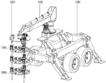
Fig. 1 is a schematic perspective view of a cantilever-type intelligent temperature measurement and detection device for a vertical shaft according to an embodiment of the present application;
fig. 2 is a schematic perspective view of a balance moving assembly according to an embodiment of the present disclosure;
fig. 3 is a schematic perspective view of a cantilever positioning assembly according to an embodiment of the present disclosure;
FIG. 4 is a perspective view of a draft guidance assembly according to an embodiment of the present disclosure;
figure 5 is a perspective view of a climbing counterbalance assembly provided in accordance with an embodiment of the present application;
fig. 6 is a schematic perspective view of a detection balance assembly according to an embodiment of the present disclosure.
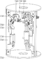
In the figure: 100-balance moving assembly; 110-a travelling carriage; 111-a traction frame; 112-a road wheel; 120-a balancing side column; 121-second transposition; 130-side column hydraulic cylinder; 131-a second rotating shaft; 140-main vertical bracing column; 141-a turntable; 142-a first transposition; 150-a main vertical hydraulic cylinder; 151-a first shaft; 300-a cantilever positioning assembly; 310-a rotating column; 311-fluted disc; 312-a cantilever stage; 320-a rotary motor; 321-a gear; 322-a mounting seat; 330-cantilever sleeve; 340-a positioning arm; 350-positioning hydraulic cylinders; 351-pipe hoop; 352-positioning seat; 500-a traction guide assembly; 510-a traction table; 511-a traction seat; 512-connecting rod; 520-a traction drum; 530-traction motor; 540-a guide seat; 541-a guide wheel; 550-a hauling rope; 551-gravity ball; 700-a climbing counterbalance assembly; 710-a climbing ring frame; 711-ring plate; 720-adjusting seat; 730-adjusting the hydraulic cylinder; 740-roller frame; 750-a first link; 760-a second link; 770-climbing wheels; 780-a climbing motor; 900 — detecting the balancing component; 910-a detection station; 911-flat pressing through groove; 920-a ranging module; 930-detecting the motor; 940-distribution tray; 941-distribution plate; 950-detecting the subject.
Detailed Description
To make the objects, technical solutions and advantages of the embodiments of the present application clearer, the technical solutions of the embodiments of the present application will be clearly and completely described below with reference to the drawings in the embodiments of the present application, and it is obvious that the described embodiments are some embodiments of the present application, but not all embodiments. All other embodiments obtained by a person of ordinary skill in the art without any inventive work based on the embodiments in the present application are within the scope of protection of the present application.
Thus, the following detailed description of the embodiments of the present application, as presented in the figures, is not intended to limit the scope of the claimed application, but is merely representative of selected embodiments of the application. All other embodiments obtained by a person of ordinary skill in the art based on the embodiments in the present application without making creative efforts shall fall within the protection scope of the present application.
It should be noted that: like reference numbers and letters refer to like items in the following figures, and thus, once an item is defined in one figure, it need not be further defined and explained in subsequent figures.
In the description of the present application, it is to be understood that the terms "center," "longitudinal," "lateral," "length," "width," "thickness," "upper," "lower," "front," "rear," "left," "right," "vertical," "horizontal," "top," "bottom," "inner," "outer," "clockwise," "counterclockwise," and the like are used in the orientations and positional relationships indicated in the drawings for convenience in describing the present application and for simplicity in description, and are not intended to indicate or imply that the referenced device or element must have a particular orientation, be constructed in a particular orientation, and be operated in a particular manner, and thus should not be considered limiting.
Furthermore, the terms "first", "second" and "first" are used for descriptive purposes only and are not to be construed as indicating or implying relative importance or implicitly indicating the number of technical features indicated. Thus, a feature defined as "first" or "second" may explicitly or implicitly include one or more of that feature. In the description of the present application, "a plurality" means two or more unless specifically limited otherwise.
In this application, unless expressly stated or limited otherwise, the terms "mounted," "connected," "secured," and the like are to be construed broadly and encompass, for example, both fixed and removable connections or integral parts thereof; either directly or indirectly through intervening media, either internally or in any other relationship. The specific meaning of the above terms in the present application can be understood by those of ordinary skill in the art as appropriate.
In this application, unless expressly stated or limited otherwise, the recitation of a first feature "on" or "under" a second feature may include the recitation of the first and second features being in direct contact, and may also include the recitation of the first and second features not being in direct contact, but being in contact with another feature between them. Also, the first feature being "on," "above" and "over" the second feature includes the first feature being directly on and obliquely above the second feature, or merely indicating that the first feature is at a higher level than the second feature. A first feature being "under," "below," and "beneath" a second feature includes the first feature being directly under and obliquely below the second feature, or simply meaning that the first feature is at a lesser elevation than the second feature.
Examples
As shown in fig. 1 to 6, the cantilever-type intelligent temperature measurement and detection device for the shaft according to the embodiment of the present application includes a balance moving assembly 100, a cantilever positioning assembly 300, a traction guide assembly 500, a climbing balance assembly 700, and a detection balance assembly 900, wherein the cantilever positioning assembly 300 is installed on the balance moving assembly 100, the traction guide assembly 500 is suspended on the cantilever positioning assembly 300, and the detection balance assembly 900 uniformly climbs below the traction guide assembly 500 by climbing the balance assembly 700. The balance moving assembly 100 moves to a safe area far away from the adjacent edge of the vertical shaft, and the balance stability of the temperature measuring detection device is kept through multiple hydraulic supports. The cantilever positioning component 300 adjusts the detection position of the temperature measurement detection device on the transverse surface of the vertical shaft. The traction guide assembly 500 is used for drawing the temperature measurement detection device to vertically lift to measure the temperature of the vertical shaft. The detection balance assembly 900 forms detection nodes below the traction guide assembly 500 to form a cage-shaped closed loop stabilization unit. The climbing counterbalance assembly 700 assists in detecting that the counterbalance assembly 900 is climbing fixed on the draft guide assembly 500.
As shown in fig. 2-6, the danger of subsidence exists on the shaft side, the operation needs to be carried out on the shaft side in the current shaft temperature detection operation, the steel wire is hung through a shaft mouth support to control the vertical lifting of the temperature measuring device, when the shaft mouth geology is subsided, the safety accidents of detection personnel and detection equipment are easily caused, and the detection steel cable rope is easily subjected to the air flow inside and outside the shaft mouth and the influence of traction, lifting and vibration to influence the swinging in the suspension process of the detection steel cable rope, the detection equipment hung on the detection steel cable rope is extremely easy to collide with the inner wall of the shaft mouth, the safety accidents of the detection equipment are caused, and the shaft temperature measurement risk is extremely outstanding.
The balance moving assembly 100 comprises a moving frame 110, a balance side column 120, a side column hydraulic cylinder 130, a main vertical support column 140 and a main vertical hydraulic cylinder 150, wherein the balance side column 120 is symmetrically and rotatably connected to the peripheral side of the moving frame 110, a second rotating seat 121 is rotatably arranged at the upper end of the balance side column 120, the balance side column 120 is in pin connection with the second rotating seat 121, the second rotating seat 121 is fixed on the moving frame 110, and the second rotating seat 121 is welded with the moving frame 110. The body of the side column hydraulic cylinder 130 is symmetrically and rotatably connected to the periphery of the movable frame 110, the body of the side column hydraulic cylinder 130 is rotatably connected to the inside of the second rotating base 121, and the side column hydraulic cylinder 130 is pin-connected to the second rotating base 121. One end of a piston rod of the side column hydraulic cylinder 130 is rotatably connected to the balance side column 120, one end of the piston rod of the side column hydraulic cylinder 130 is provided with a second rotating shaft 131, two ends of the second rotating shaft 131 are rotatably connected to the balance side column 120, a bearing is arranged in the specific balance side column 120, and two ends of the second rotating shaft 131 rotate to the position between the bearing and the balance side column 120.
Wherein the jamb hydraulic cylinder 130 controls the rotational support and retraction of the balance jamb 120. One end of the main vertical supporting column 140 is symmetrically and rotatably connected in the moving frame 110, a first rotating seat 142 is rotatably arranged at the lower end of the main vertical supporting column 140, the main vertical supporting column 140 is in pin connection with the first rotating seat 142, the first rotating seat 142 is fixed in the moving frame 110, the first rotating seat 142 is welded with the moving frame 110, a cylinder body of the main vertical hydraulic cylinder 150 is symmetrically and rotatably connected in the moving frame 110, the cylinder body of the main vertical hydraulic cylinder 150 is rotatably connected in the first rotating seat 142, and the main vertical hydraulic cylinder 150 is in pin connection with the first rotating seat 142. One end of a piston rod of the main vertical hydraulic cylinder 150 is rotatably connected to the main vertical supporting column 140, one end of the piston rod of the main vertical hydraulic cylinder 150 is provided with a first rotating shaft 151, the main vertical hydraulic cylinder 150 is connected with the first rotating shaft 151 through a pin, two ends of the first rotating shaft 151 are rotated in the main vertical supporting column 140, a bearing is arranged in the main vertical supporting column 140, two ends of the first rotating shaft 151 are rotatably connected between the bearings, and in a specific embodiment, the main vertical hydraulic cylinder 150 controls the main vertical supporting column 140 to rotatably support and furl.
Wherein, moving frame 110 one end and being provided with traction frame 111, make things convenient for temperature measurement detection device's traction, moving frame 110 lower extreme symmetry rotates and is provided with walking wheel 112, makes things convenient for temperature measurement detection device's removal.
The cantilever positioning assembly 300 comprises a rotary column 310, a rotary motor 320, a cantilever sleeve 330, a positioning arm 340 and a positioning hydraulic cylinder 350, wherein the lower end of the rotary column 310 is rotatably connected to the main vertical supporting column 140, a rotary table 141 is arranged at the top of the main vertical supporting column 140, the rotary table 141 is in threaded connection with the main vertical supporting column 140, and the lower end of the rotary column 310 is rotated in the rotary table 141. The body of the rotary motor 320 is arranged on the main vertical supporting column 140, the body of the rotary motor 320 is provided with a mounting seat 322, the mounting seat 322 is fixed on the rotary table 141, and the mounting seat 322 is respectively screwed with the rotary motor 320 and the rotary table 141. The output end of the rotary motor 320 is meshed with the lower end of the main vertical supporting column 140, the fluted disc 311 is fixedly sleeved at the lower end of the rotary column 310, the fluted disc 311 is in screw connection with the rotary column 310, a gear 321 is fixed at the output end of the rotary motor 320, the gear 321 is in key connection with the rotary motor 320, the gear 321 is meshed with the fluted disc 311, the rotary column 310 is controlled to rotate by the specific rotary motor 320, one end of the cantilever sleeve 330 is arranged on the rotary column 310, and the top of the rotary column 310 is provided with the cantilever table 312.
Wherein, one end of the cantilever sleeve 330 is fixed in the cantilever table 312, and the cantilever table 312 is respectively screwed with the rotary column 310 and the cantilever sleeve 330. One end of the positioning arm 340 penetrates through the cantilever sleeve 330 in a sliding manner, the cylinder body of the positioning hydraulic cylinder 350 is arranged on the cantilever sleeve 330, the cylinder body of the positioning hydraulic cylinder 350 is provided with a pipe hoop 351, the pipe hoop 351 is fixed on the cantilever sleeve 330, the pipe hoop 351 is in threaded connection with the cantilever sleeve 330, one end of the piston rod of the positioning hydraulic cylinder 350 is fixed at the other end of the positioning arm 340, one end of the piston rod of the positioning hydraulic cylinder 350 is provided with a positioning seat 352, the positioning seat 352 is fixed on the positioning arm 340, and the positioning seat 352 is in threaded connection with the positioning arm 340 and the positioning hydraulic cylinder 350 respectively.
The movable frame 110 is moved to a safe area far away from the adjacent edge of a vertical shaft through the traction frame 111 and the traveling wheels 112, the movable frame 110 is stably supported on the ground by controlling the rotation and falling of the balance side columns 120 through the extension and contraction of the side column hydraulic cylinders 130, the main upright supporting columns 140 are controlled to rotate and lift through the extension and contraction of the main upright hydraulic cylinders 150, and the support safety and stability of the temperature measurement detection device are improved through double hydraulic support. The temperature measurement detection device is controlled to face towards the vertical shaft through the rotary motor 320, the sliding length of the positioning arm 340 in the cantilever sleeve 330 is controlled through the positioning hydraulic cylinder 350, the temperature measurement detection device is moved to the upper portion of the vertical shaft, the safety and stability of the temperature measurement device are improved through clamping of the hydraulic sleeve, the remote operation of vertical shaft temperature measurement is achieved through the cooperation of the movable frame 110 while the measurement point adjustment of the temperature measurement detection device is achieved, and risks caused by near-distance measurement of the wellhead are reduced.
The traction guide assembly 500 comprises a traction table 510, a traction roller 520, a traction motor 530, a guide seat 540 and a traction rope 550, wherein the traction table 510 is suspended at the other end of the positioning arm 340, and the traction table 510 is screwed with the positioning arm 340. The traction roller 520 symmetrically rotates on the traction table 510, the traction table 510 is symmetrically provided with traction seats 511, the traction seats 511 are in threaded connection with the traction table 510, two ends of the traction roller 520 are rotatably connected between the traction seats 511, bearings are arranged at two ends of each traction seat 511, two ends of the traction roller 520 are rotatably connected between the bearings, the traction motor 530 is symmetrically arranged on the traction table 510, the traction motor 530 is fixed on the traction seats 511, the traction seats 511 are in threaded connection with the traction motor 530, a connecting rod 512 is arranged between the upper ends of the traction seats 511, and the connecting rod 512 is in threaded connection with the traction seats 511, so that the supporting strength of the traction seats 511 is improved. The output end of the traction motor 530 is transmitted to the traction roller 520, and the traction motor 530 is coupled with the traction roller 520. The guide seat 540 is symmetrically hung at the bottom of the traction table 510, and the guide seat 540 is in threaded connection with the traction table 510.
The upper end of the traction rope 550 is wound on the surface of the traction roller 520, the lower end of the traction rope 550 penetrates through the guide seat 540 in a sliding mode, guide wheels 541 are symmetrically arranged in the guide seat 540 in a rotating mode, the guide wheels 541 are connected with the guide seat 540 in a pin shaft mode, the traction rope 550 penetrates through the guide wheels 541 in a sliding mode, a groove is formed in the surface of each specific guide wheel 541 to guide the traction rope 550 in a limiting mode, a gravity ball 551 is arranged at the lower end of the traction rope 550, and the traction part of the traction rope 550 is made to be vertical all the time.
Climbing balance assembly 700 includes climbing ring frame 710, adjusts seat 720, adjusts hydraulic cylinder 730, gyro wheel frame 740, first connecting rod 750, second connecting rod 760, climbing wheel 770 and climbing motor 780, and climbing ring frame 710 cup joints in the haulage rope 550 surface, adjusts seat 720 symmetry and slides in climbing ring frame 710, has seted up the spout on the concrete climbing ring frame 710, rotates on adjusting seat 720 and is provided with the roller, and the roller slides in the spout. The cylinder body of the adjusting hydraulic cylinder 730 is symmetrically arranged on the climbing ring frame 710, the adjusting hydraulic cylinder 730 is in threaded connection with the climbing ring frame 710, one end of the piston rod of the adjusting hydraulic cylinder 730 is fixed on the adjusting seat 720, and the adjusting hydraulic cylinder 730 controls the lifting of the adjusting seat 720. The roller frame 740 is symmetrically arranged in the climbing ring frame 710, one end of a first connecting rod 750 is rotatably connected to the climbing ring frame 710, the other end of the first connecting rod 750 is rotatably connected to the roller frame 740, the first connecting rod 750 is respectively in pin connection with the climbing ring frame 710 and the roller frame 740, one end of a second connecting rod 760 is rotatably connected to the adjusting seat 720, the other end of the second connecting rod 760 is rotatably connected to the roller frame 740, the second connecting rod 760 is respectively in pin connection with the adjusting seat 720 and the roller frame 740, the climbing wheel 770 is rotatably connected to the roller frame 740, the body of the climbing motor 780 is arranged on the roller frame 740, the climbing motor 780 is in key connection with the roller frame 740, the output end of the climbing motor 780 is transmitted to the climbing wheel 770, and the climbing motor 780 is in key connection with the climbing wheel 770.
Detect balanced subassembly 900 including detecting platform 910, range finding module 920, detect motor 930, distribution disc 940 and detection main part 950, it sets up in climbing ring frame 710 bottom to detect platform 910, climbing ring frame 710 both ends are provided with the crown plate 711, the crown plate 711 and climbing ring frame 710 spiro union, make climbing ring frame 710 form stable closed loop, increase the support stability of climbing ring frame 710, one of them crown plate 711 is fixed in and detects the platform 910 top, crown plate 711 and detection platform 910 spiro union, it is fixed that concrete detection platform 910 goes up and down at haulage rope 550 through climbing balanced subassembly 700, another crown plate 711 is laminated in another detection platform 910 bottom, it is spacing to adjacent detection platform 910. The range finding module 920 evenly sets up on examining test table 910, and range finding module 920 and examining test table 910 spiro union, range finding module 920 towards another examine test table 910, and the fuselage of detecting motor 930 sets up in examining test table 910 top center, detects motor 930 and examines test table 910 spiro union, and distribution disc 940 is fixed in the output of detecting motor 930, and distribution disc 940 and detecting motor 930 spiro union, and detection main part 950 evenly sets up in distribution disc 940 week side.
Wherein, the distribution plate 941 is evenly provided with around the distribution plate 940, and distribution plate 941 and distribution plate 940 integrated into one piece detect main part 950 and set up on distribution plate 941, detect main part 950 and measure such as temperature measurement, geological composition, image to the shaft inside. The surface of the detection platform 910 is uniformly provided with flat pressing through grooves 911, and the flat pressing through grooves 911 are communicated with the outside atmosphere, so that the impact of airflow inside the vertical shaft on the detection device is reduced.
As shown in fig. 2-6, the existing vertical shaft has a high depth drop, the temperature measurement detection device needs to detect the temperature difference between the upper part and the lower part of the vertical shaft under the traction and lifting of the cable, and the bottom of the cable swings greatly and is easy to rotate, so the temperature measurement detection device can only be suspended in the vertical shaft and cannot accurately detect the temperature of the inner wall of the vertical shaft. The structure of the ground rock of the vertical shaft well wall is complex, and the distribution difference of the ground rock and the underground water layer exists along with the change of the depth of the vertical shaft, so that the temperature measurement detection device is required to carry out all-dimensional detection on the vertical shaft well wall.
The side column hydraulic cylinder 130 telescopically controls the rotation and falling of the balance side column 120, the main vertical hydraulic cylinder 150 telescopically controls the rotation and lifting support of the main vertical supporting column 140, the balance installation of the temperature measurement detection fixing support is realized through the structure, a stable supporting platform is provided for the underground measurement of the vertical shaft, and the measurement precision of the temperature measurement detection device is increased. The moving direction of the temperature measurement detection device is accurately controlled through the rotary motor 320, the sliding distance of the positioning arm 340 on the cantilever sleeve 330 is accurately controlled through the positioning hydraulic cylinder 350, the temperature measurement detection device can conveniently and accurately move in the space in the shaft, and the profile of the inner wall of the shaft is subjected to accurate temperature measurement detection. Control haulage rope 550 through a plurality of traction motor 530 and pull temperature measurement detection device, increase temperature measurement detection device's the stress point that hangs, through the rocking that temperature measurement detection device was offset in many haulage rope 550 self swings, improve temperature measurement detection device's suspension stability and temperature measurement detection precision. Detect platform 910 about to carry out the distance through evenly distributed's range finding module 920 and detect and transmit for remote terminal, remote terminal passes through balance analysis and gives corresponding climbing motor 780 with signal transmission, and corresponding climbing motor 780 control climbing wheel 770 moves in the surperficial lift of haulage rope 550 to guarantee the balance of temperature measurement detection device platform, improve temperature measurement detection device's detection precision. The adjusting hydraulic cylinder 730 controls a plurality of groups of climbing wheels 770 to clamp the traction ropes 550, so that the distribution disc 940 on one side of the annular plate 711 is sleeved and fixed on the plurality of groups of traction ropes 550 to form a stable closed-loop traction detection platform, the swing amplitude of the bottom of the traction ropes 550 is reduced, and the detection precision of the temperature measurement detection device is improved. When multiunit measurement testing platform's setting reinforcing suspension stability, through the ladder measurement of constant height, need not temperature measuring device later stage and go up and down to remove, reduce to remove and to rock and to carry out the all-round accurate temperature measurement of while section from top to bottom to the shaft, through detecting motor 930 control temperature measuring device's turned angle, carry out all-round accurate scanning temperature measurement to the shaft cross-section and detect.
Specifically, this cantilever type intelligence temperature measurement detection device for shaft's theory of operation: the movable frame 110 is moved to a safe area far away from the adjacent edge of a vertical shaft through the traction frame 111 and the traveling wheels 112, the movable frame 110 is stably supported on the ground through the rotation and falling of the balance side columns 120 controlled by the telescopic control of the side column hydraulic cylinders 130, the main vertical supporting columns 140 are controlled by the telescopic control of the main vertical hydraulic cylinders 150 to rotate to lift and support, and the support safety and stability of the temperature measurement detection device are improved through double hydraulic support. The temperature measurement detection device is controlled to face towards the vertical shaft through the rotary motor 320, the sliding length of the positioning arm 340 in the cantilever sleeve 330 is controlled through the positioning hydraulic cylinder 350, the temperature measurement detection device is moved to the upper portion of the vertical shaft, the safety and stability of the temperature measurement device are improved through clamping of the hydraulic sleeve, the remote operation of vertical shaft temperature measurement is achieved through the cooperation of the movable frame 110 while the measurement point adjustment of the temperature measurement detection device is achieved, and risks caused by near-distance measurement of the wellhead are reduced.
Further, control haulage rope 550 through a plurality of traction motor 530 and pull temperature measurement detection device, many haulage rope 550 self swing inconsistent offset hang rocking of in-process, reduce temperature measurement detection device swing striking shaft inner wall, it is spacing to slide haulage rope 550 through leading wheel 541, reduce the haulage rope 550 that causes and shift in the traction process, improve the temperature measurement and detect the safety and stability in the use. The plurality of groups of climbing wheels 770 are controlled to clamp the traction ropes 550 through adjusting the hydraulic cylinder 730, so that the distribution disc 940 on one side of the ring plate 711 is sleeved and fixed on the plurality of groups of traction ropes 550 to form stable closed-loop traction detection nodes one by one, the swing amplitude of the bottom of the traction rope 550 is reduced, the temperature measurement detection device is swung due to the fact that the traction rope 550 swings, the temperature measurement lifting control is not influenced, the temperature measurement detection device swings to impact the inner wall of a vertical shaft, and the safety stability of the temperature measurement detection in the use process is improved.
In addition, the rotation and falling of the balance side column 120 are controlled by the telescopic control of the side column hydraulic cylinder 130, the rotation and lifting support of the main vertical supporting column 140 is controlled by the telescopic control of the main vertical hydraulic cylinder 150, the balance installation of the temperature measurement detection fixing support is realized through the structure, a stable supporting platform is provided for the vertical shaft underground measurement, and the measurement precision of the temperature measurement detection device is increased. The moving direction of the temperature measurement detection device is accurately controlled through the rotary motor 320, the sliding distance of the positioning arm 340 in the cantilever sleeve 330 is accurately controlled through the positioning hydraulic cylinder 350, the temperature measurement detection device can conveniently and accurately move in the space in the shaft, and the temperature measurement detection is accurately carried out on the contour of the inner wall of the shaft. Control haulage rope 550 through a plurality of traction motor 530 and pull temperature measurement detection device, increase temperature measurement detection device's the stress point that hangs, through the rocking that temperature measurement detection device was offset in many haulage rope 550 self swings, improve temperature measurement detection device's suspension stability and temperature measurement detection precision. Detect platform 910 about to carry out the distance through evenly distributed's range finding module 920 and detect and transmit for remote terminal, remote terminal passes through balance analysis and gives corresponding climbing motor 780 with signal transmission, and corresponding climbing motor 780 control climbing wheel 770 moves in the surperficial lift of haulage rope 550 to guarantee the balance of temperature measurement detection device platform, improve temperature measurement detection device's detection precision. The adjusting hydraulic cylinder 730 controls a plurality of groups of climbing wheels 770 to clamp the traction ropes 550, so that the distribution disc 940 on one side of the annular plate 711 is sleeved and fixed on the plurality of groups of traction ropes 550 to form a stable closed-loop traction detection platform, the swing amplitude of the bottom of the traction ropes 550 is reduced, and the detection precision of the temperature measurement detection device is improved. When multiunit measurement testing platform's setting reinforcing suspension stability, through the equal-height ladder measurement, need not temperature measuring device later stage lift and remove, reduce to remove and to shake and to carry out the all-round accurate temperature measurement of while section from top to bottom to the shaft, through detecting motor 930 control temperature measuring device's turned angle, carry out all-round accurate scanning temperature measurement to the shaft cross-section and detect.
It should be noted that, the side pillar hydraulic cylinder 130, the main vertical hydraulic cylinder 150, the rotating motor 320, the positioning hydraulic cylinder 350, the traction motor 530, the distance measuring module 920, the detection motor 930, and the detection main body 950, the specific model specification needs to be determined according to the actual specification of the device, and the specific model selection calculation method adopts the prior art in the field, and therefore details are not repeated.
The power supply and the principle of the side pillar hydraulic cylinder 130, the main vertical hydraulic cylinder 150, the rotation motor 320, the positioning hydraulic cylinder 350, the traction motor 530, the distance measuring module 920, the detection motor 930 and the detection body 950 are clear to those skilled in the art and will not be described in detail herein.
The above description is only a preferred embodiment of the present application and is not intended to limit the present application, and various modifications and changes may be made by those skilled in the art. Any modification, equivalent replacement, improvement and the like made within the spirit and principle of the present application shall be included in the protection scope of the present application.
Claims (5)
1. The utility model provides a cantilever type intelligence temperature measurement detection device for shaft, its characterized in that, includes balanced removal subassembly (100), balanced removal subassembly (100) including moving frame (110), balanced side post (120), side post pneumatic cylinder (130), main upright support post (140) and main upright pneumatic cylinder (150), balanced side post (120) symmetry rotate connect in moving frame (110) week side, balanced side post (120) upper end is rotated and is provided with second swivel mount (121), second swivel mount (121) are fixed in on moving frame (110), side post pneumatic cylinder (130) body symmetry rotate connect in moving frame (110) week side, side post pneumatic cylinder (130) body rotate connect in second swivel mount (121), side post pneumatic cylinder (130) piston rod one end rotate connect in on balanced side post (120), one end of a piston rod of the side column hydraulic cylinder (130) is provided with a second rotating shaft (131), two ends of the second rotating shaft (131) rotate in the balance side column (120), one end of the main vertical supporting column (140) is symmetrically and rotationally connected in the movable frame (110), a first swivel base (142) is rotatably arranged at the lower end of the main vertical supporting column (140), the first swivel base (142) is fixed in the movable frame (110), the main vertical hydraulic cylinder (150) is symmetrically and rotationally connected in the movable frame (110), the main vertical hydraulic cylinder (150) is rotatably connected with the first rotating base (142), one end of a piston rod of the main vertical hydraulic cylinder (150) is rotationally connected to the main vertical supporting column (140), one end of a piston rod of the main vertical hydraulic cylinder (150) is provided with a first rotating shaft (151), two ends of the first rotating shaft (151) rotate in the main vertical supporting column (140);
the cantilever positioning assembly (300) comprises a rotary column (310), a rotary motor (320), a cantilever sleeve (330), a positioning arm (340) and a positioning hydraulic cylinder (350), wherein the lower end of the rotary column (310) is rotatably connected to the main vertical supporting column (140), a rotary table (141) is arranged at the top of the main vertical supporting column (140), the lower end of the rotary column (310) is rotated in the rotary table (141), a body of the rotary motor (320) is arranged on the main vertical supporting column (140), an output end of the rotary motor (320) is meshed with the lower end of the main vertical supporting column (140), a fluted disc (311) is fixedly sleeved at the lower end of the rotary column (310), a gear (321) is fixed at the output end of the rotary motor (320), the gear (321) is meshed with the fluted disc (311), one end of the cantilever sleeve (330) is arranged on the rotary column (310), one end of the positioning arm (340) penetrates through the cantilever sleeve (330) in a sliding manner, the cylinder body of the positioning hydraulic cylinder (350) is arranged on the cantilever sleeve (330), and one end of the piston rod of the positioning hydraulic cylinder (350) is fixed at the other end of the positioning arm (340);
the traction guide assembly (500) comprises a traction table (510), a traction roller (520), a traction motor (530), a guide seat (540) and a traction rope (550), the traction table (510) is suspended at the other end of the positioning arm (340), the traction roller (520) symmetrically rotates on the traction table (510), the body of the traction motor (530) is symmetrically arranged on the traction table (510), the output end of the traction motor (530) is transmitted to the traction roller (520), the guide seat (540) is symmetrically suspended at the bottom of the traction table (510), the upper end of the traction rope (550) is wound on the surface of the traction roller (520), and the lower end of the traction rope (550) is slidably penetrated in the guide seat (540);
climbing balance assembly (700), climbing balance assembly (700) includes climbing ring frame (710), regulation seat (720), regulation pneumatic cylinder (730), gyro wheel frame (740), first connecting rod (750), second connecting rod (760), climbing wheel (770) and climbing motor (780), climbing ring frame (710) cup joint in haulage rope (550) surface, adjust seat (720) symmetry slip in climbing ring frame (710), adjust pneumatic cylinder (730) cylinder body symmetry and set up in on climbing ring frame (710), adjust pneumatic cylinder (730) piston rod one end be fixed in adjust on the seat (720), gyro wheel frame (740) symmetry sets up in climbing ring frame (710), first connecting rod (750) one end rotate connect in on climbing ring frame (710), the other end of first connecting rod (750) rotates and connects on gyro wheel frame (740), one end of the second connecting rod (760) is rotatably connected to the adjusting seat (720), the other end of the second connecting rod (760) is rotated on the roller frame (740), the climbing wheel (770) is rotated in the roller frame (740), the body of the climbing motor (780) is arranged on the roller frame (740), and the output end of the climbing motor (780) is transmitted to the climbing wheel (770);
detect balanced subassembly (900), detect balanced subassembly (900) including detecting platform (910), ranging module (920), detection motor (930), distribution plate (940) and detect main part (950), detect platform (910) set up in climbing ring frame (710) bottom, ranging module (920) evenly set up in detect on the platform (910), ranging module (920) orientation is another detect platform (910), detect motor (930) fuselage set up in detect platform (910) top center, distribution plate (940) are fixed in detect motor (930) output, detect main part (950) evenly set up in distribution plate (940) week side.
2. The cantilever-type intelligent temperature measurement and detection device for the shaft according to claim 1, wherein the body of the rotary motor (320) is provided with a mounting seat (322), and the mounting seat (322) is fixed on the rotary table (141).
3. The cantilever type intelligent temperature measurement and detection device for the shaft according to claim 1, wherein one end of the movable vehicle frame (110) is provided with a traction frame (111), and the lower end of the movable vehicle frame (110) is symmetrically and rotatably provided with traveling wheels (112).
4. The cantilever-type intelligent temperature measurement and detection device for the shaft according to claim 1, wherein a cantilever table (312) is arranged at the top of the rotary column (310), and one end of the cantilever sleeve (330) is fixed in the cantilever table (312).
5. The cantilever-type intelligent temperature measurement and detection device for the vertical shaft is characterized in that a pipe hoop (351) is arranged on a cylinder body of the positioning hydraulic cylinder (350), the pipe hoop (351) is fixed on the cantilever sleeve (330), a positioning seat (352) is arranged at one end of a piston rod of the positioning hydraulic cylinder (350), and the positioning seat (352) is fixed on the positioning arm (340).
Priority Applications (1)
| Application Number | Priority Date | Filing Date | Title |
|---|---|---|---|
| CN202210336081.7A CN114414074B (en) | 2022-04-01 | 2022-04-01 | Cantilever type intelligent temperature measurement and detection device for vertical shaft |
Applications Claiming Priority (1)
| Application Number | Priority Date | Filing Date | Title |
|---|---|---|---|
| CN202210336081.7A CN114414074B (en) | 2022-04-01 | 2022-04-01 | Cantilever type intelligent temperature measurement and detection device for vertical shaft |
Publications (2)
| Publication Number | Publication Date |
|---|---|
| CN114414074A CN114414074A (en) | 2022-04-29 |
| CN114414074B true CN114414074B (en) | 2022-07-08 |
Family
ID=81264393
Family Applications (1)
| Application Number | Title | Priority Date | Filing Date |
|---|---|---|---|
| CN202210336081.7A Active CN114414074B (en) | 2022-04-01 | 2022-04-01 | Cantilever type intelligent temperature measurement and detection device for vertical shaft |
Country Status (1)
| Country | Link |
|---|---|
| CN (1) | CN114414074B (en) |
Families Citing this family (2)
| Publication number | Priority date | Publication date | Assignee | Title |
|---|---|---|---|---|
| CN116734131B (en) * | 2023-05-31 | 2025-09-05 | 斯比夫(西安)照明技术有限公司 | Laser positioning device and method for detection equipment |
| CN116929582B (en) * | 2023-09-15 | 2023-11-24 | 山西省第二地质工程勘察院有限公司 | Geothermal well wall of a well temperature monitoring devices |
Citations (17)
| Publication number | Priority date | Publication date | Assignee | Title |
|---|---|---|---|---|
| SU1766830A1 (en) * | 1990-04-12 | 1992-10-07 | Производственное Объединение "Уралвагонзавод Им.Ф.Э.Дзержинского" | Cantilever crane |
| CN1093633A (en) * | 1992-09-30 | 1994-10-19 | 利顿工业自动化系统有限公司 | The retaining mechanism of contouring head assembly for multiple belt grinding machine |
| JPH10231505A (en) * | 1997-02-18 | 1998-09-02 | Nippon Sharyo Seizo Kaisha Ltd | Traffic information display board support device |
| KR101230559B1 (en) * | 2011-08-31 | 2013-02-07 | 주식회사 엠에스티 | A solar tracking apparatus |
| CN103190990A (en) * | 2013-04-10 | 2013-07-10 | 海南大学 | Automatic bed-transfer stretcher |
| CN103323246A (en) * | 2013-07-02 | 2013-09-25 | 吉林大学 | Electric multiple unit transmission system axle box bearing six-degree-of-freedom dynamic simulation load test platform |
| CN103806654A (en) * | 2012-11-06 | 2014-05-21 | 中国五冶集团有限公司 | Hydraulic support system for elevator shaft mold and operating method thereof |
| CN105041329A (en) * | 2015-08-27 | 2015-11-11 | 安徽理工大学 | Six-freedom-degree series-parallel full-hydraulic tunneling machine |
| CN105415366A (en) * | 2015-12-28 | 2016-03-23 | 天津市中恒科贸有限公司 | Manipulator for grabbing plastic special-shaped body |
| CN105822614A (en) * | 2016-04-14 | 2016-08-03 | 南京航空航天大学 | Electro-hydrostatic actuator |
| CN109132887A (en) * | 2018-08-31 | 2019-01-04 | 扬州达安运输有限公司 | A kind of cargo handling machinery boom with telescopic adjustment function |
| CN209673234U (en) * | 2019-04-03 | 2019-11-22 | 中铁工程装备集团隧道设备制造有限公司 | Measuring temperature of bearing structure and cantilever excavator cutting arm |
| CN209861696U (en) * | 2019-04-18 | 2019-12-31 | 孟爱国 | Green engineering gardens trimming machine with spraying function |
| CN110883769A (en) * | 2019-12-01 | 2020-03-17 | 杨国丽 | Foldable industrial mechanical arm |
| CN111232855A (en) * | 2020-03-18 | 2020-06-05 | 上海贺力液压机电有限公司 | Rotatable hydraulic type cantilever lifting device |
| CN113232880A (en) * | 2021-07-08 | 2021-08-10 | 深圳市勘察研究院有限公司 | Method for automatic extraction of oblique photography suspension arm and features |
| CN114234886A (en) * | 2021-11-09 | 2022-03-25 | 深圳市勘察研究院有限公司 | Karst early warning monitoring devices that collapses |
Family Cites Families (2)
| Publication number | Priority date | Publication date | Assignee | Title |
|---|---|---|---|---|
| CN103806644B (en) * | 2012-11-06 | 2016-02-03 | 中国五冶集团有限公司 | For electrical lift shaft form hydraulic telescopic device and operation method thereof |
| CN113623506B (en) * | 2021-10-08 | 2022-01-04 | 成都理工大学 | Rotary scanning type binocular photogrammetry device |
-
2022
- 2022-04-01 CN CN202210336081.7A patent/CN114414074B/en active Active
Patent Citations (17)
| Publication number | Priority date | Publication date | Assignee | Title |
|---|---|---|---|---|
| SU1766830A1 (en) * | 1990-04-12 | 1992-10-07 | Производственное Объединение "Уралвагонзавод Им.Ф.Э.Дзержинского" | Cantilever crane |
| CN1093633A (en) * | 1992-09-30 | 1994-10-19 | 利顿工业自动化系统有限公司 | The retaining mechanism of contouring head assembly for multiple belt grinding machine |
| JPH10231505A (en) * | 1997-02-18 | 1998-09-02 | Nippon Sharyo Seizo Kaisha Ltd | Traffic information display board support device |
| KR101230559B1 (en) * | 2011-08-31 | 2013-02-07 | 주식회사 엠에스티 | A solar tracking apparatus |
| CN103806654A (en) * | 2012-11-06 | 2014-05-21 | 中国五冶集团有限公司 | Hydraulic support system for elevator shaft mold and operating method thereof |
| CN103190990A (en) * | 2013-04-10 | 2013-07-10 | 海南大学 | Automatic bed-transfer stretcher |
| CN103323246A (en) * | 2013-07-02 | 2013-09-25 | 吉林大学 | Electric multiple unit transmission system axle box bearing six-degree-of-freedom dynamic simulation load test platform |
| CN105041329A (en) * | 2015-08-27 | 2015-11-11 | 安徽理工大学 | Six-freedom-degree series-parallel full-hydraulic tunneling machine |
| CN105415366A (en) * | 2015-12-28 | 2016-03-23 | 天津市中恒科贸有限公司 | Manipulator for grabbing plastic special-shaped body |
| CN105822614A (en) * | 2016-04-14 | 2016-08-03 | 南京航空航天大学 | Electro-hydrostatic actuator |
| CN109132887A (en) * | 2018-08-31 | 2019-01-04 | 扬州达安运输有限公司 | A kind of cargo handling machinery boom with telescopic adjustment function |
| CN209673234U (en) * | 2019-04-03 | 2019-11-22 | 中铁工程装备集团隧道设备制造有限公司 | Measuring temperature of bearing structure and cantilever excavator cutting arm |
| CN209861696U (en) * | 2019-04-18 | 2019-12-31 | 孟爱国 | Green engineering gardens trimming machine with spraying function |
| CN110883769A (en) * | 2019-12-01 | 2020-03-17 | 杨国丽 | Foldable industrial mechanical arm |
| CN111232855A (en) * | 2020-03-18 | 2020-06-05 | 上海贺力液压机电有限公司 | Rotatable hydraulic type cantilever lifting device |
| CN113232880A (en) * | 2021-07-08 | 2021-08-10 | 深圳市勘察研究院有限公司 | Method for automatic extraction of oblique photography suspension arm and features |
| CN114234886A (en) * | 2021-11-09 | 2022-03-25 | 深圳市勘察研究院有限公司 | Karst early warning monitoring devices that collapses |
Non-Patent Citations (2)
| Title |
|---|
| 刘庆修.大直径深孔载人救援提升装备关键技术研究.《CNKI》.2019,全文. * |
| 刘磊.框架—支撑结构体系的分类及优缺点.《山西建筑》.2007,全文. * |
Also Published As
| Publication number | Publication date |
|---|---|
| CN114414074A (en) | 2022-04-29 |
Similar Documents
| Publication | Publication Date | Title |
|---|---|---|
| CN111594144A (en) | Screw drill tool, vertical drilling tool test method and simulated well deviation test equipment | |
| CN114229049B (en) | A low gravity simulation device and method based on weight reduction counterweight and inclination sensing | |
| CN114414074A (en) | Cantilever type intelligent temperature measurement and detection device for vertical shaft | |
| CN112684815B (en) | An intelligent control system for bridge rotation status | |
| CN112681407A (en) | Pile foundation pore-forming quality detection device and detection method thereof | |
| CN212807051U (en) | A device for detecting the verticality of a pile hole | |
| CN213579352U (en) | Mine underground lofting device | |
| CN112320568A (en) | Balance adjusting mechanism for vertical lifting of travelling crane | |
| CN119618169B (en) | A road slope measuring instrument | |
| CN212642704U (en) | Simulated drilling well deviation testing equipment | |
| CN120368933A (en) | Wall surface measuring and detecting device for building construction | |
| CN218937419U (en) | Bridge construction is with pier straightness detection device that hangs down | |
| CN219585702U (en) | Bank balance fixing device for hydrological measuring instrument | |
| CN212432168U (en) | A vertical detection mechanism for engineering supervision | |
| CN220552426U (en) | Underground operation bottom plate leveling detection device | |
| CN219416422U (en) | Portable weight calibrating device | |
| CN112747211A (en) | Self-driven positioning device for relative water depth | |
| CN216126504U (en) | Lifting mechanism of forging manipulator | |
| CN114609408B (en) | A multifunctional water flow velocity measuring device | |
| CN114111694B (en) | Anti-slide pile deformation monitoring device and failure early warning system | |
| CN218090772U (en) | Self-balancing angle limiter of pile bottom solution detecting instrument | |
| CN216483080U (en) | A vertical measuring device for mining | |
| CN116658817A (en) | Automatic balance compensation system and method for LNG storage tank air pressure lifting roof | |
| CN217738261U (en) | Engineering quality detects with straightness detection device that hangs down | |
| WO2018107933A1 (en) | Device and method for measuring rotation angles of hanging scaffold |
Legal Events
| Date | Code | Title | Description |
|---|---|---|---|
| PB01 | Publication | ||
| PB01 | Publication | ||
| SE01 | Entry into force of request for substantive examination | ||
| SE01 | Entry into force of request for substantive examination | ||
| GR01 | Patent grant | ||
| GR01 | Patent grant |