CN114413193A - Highlight LED flashlight lamp holder - Google Patents
Highlight LED flashlight lamp holder Download PDFInfo
- Publication number
- CN114413193A CN114413193A CN202011174477.3A CN202011174477A CN114413193A CN 114413193 A CN114413193 A CN 114413193A CN 202011174477 A CN202011174477 A CN 202011174477A CN 114413193 A CN114413193 A CN 114413193A
- Authority
- CN
- China
- Prior art keywords
- shell
- plate
- lamp holder
- heat dissipation
- block
- Prior art date
- Legal status (The legal status is an assumption and is not a legal conclusion. Google has not performed a legal analysis and makes no representation as to the accuracy of the status listed.)
- Withdrawn
Links
- 230000017525 heat dissipation Effects 0.000 claims abstract description 21
- 230000007246 mechanism Effects 0.000 claims abstract description 17
- 239000011521 glass Substances 0.000 claims abstract description 10
- 230000004313 glare Effects 0.000 claims 7
- 239000000428 dust Substances 0.000 abstract description 9
- 230000001681 protective effect Effects 0.000 description 7
- 230000000694 effects Effects 0.000 description 4
- 238000010586 diagram Methods 0.000 description 3
- 238000009434 installation Methods 0.000 description 2
- 230000002265 prevention Effects 0.000 description 2
- 238000009825 accumulation Methods 0.000 description 1
- 238000004891 communication Methods 0.000 description 1
- 230000007547 defect Effects 0.000 description 1
- 238000000034 method Methods 0.000 description 1
- 238000012986 modification Methods 0.000 description 1
- 230000004048 modification Effects 0.000 description 1
- 230000005855 radiation Effects 0.000 description 1
Images


Classifications
-
- F—MECHANICAL ENGINEERING; LIGHTING; HEATING; WEAPONS; BLASTING
- F21—LIGHTING
- F21L—LIGHTING DEVICES OR SYSTEMS THEREOF, BEING PORTABLE OR SPECIALLY ADAPTED FOR TRANSPORTATION
- F21L4/00—Electric lighting devices with self-contained electric batteries or cells
- F21L4/005—Electric lighting devices with self-contained electric batteries or cells the device being a pocket lamp
-
- F—MECHANICAL ENGINEERING; LIGHTING; HEATING; WEAPONS; BLASTING
- F21—LIGHTING
- F21V—FUNCTIONAL FEATURES OR DETAILS OF LIGHTING DEVICES OR SYSTEMS THEREOF; STRUCTURAL COMBINATIONS OF LIGHTING DEVICES WITH OTHER ARTICLES, NOT OTHERWISE PROVIDED FOR
- F21V15/00—Protecting lighting devices from damage
- F21V15/01—Housings, e.g. material or assembling of housing parts
-
- F—MECHANICAL ENGINEERING; LIGHTING; HEATING; WEAPONS; BLASTING
- F21—LIGHTING
- F21V—FUNCTIONAL FEATURES OR DETAILS OF LIGHTING DEVICES OR SYSTEMS THEREOF; STRUCTURAL COMBINATIONS OF LIGHTING DEVICES WITH OTHER ARTICLES, NOT OTHERWISE PROVIDED FOR
- F21V29/00—Protecting lighting devices from thermal damage; Cooling or heating arrangements specially adapted for lighting devices or systems
- F21V29/50—Cooling arrangements
- F21V29/502—Cooling arrangements characterised by the adaptation for cooling of specific components
- F21V29/503—Cooling arrangements characterised by the adaptation for cooling of specific components of light sources
-
- F—MECHANICAL ENGINEERING; LIGHTING; HEATING; WEAPONS; BLASTING
- F21—LIGHTING
- F21V—FUNCTIONAL FEATURES OR DETAILS OF LIGHTING DEVICES OR SYSTEMS THEREOF; STRUCTURAL COMBINATIONS OF LIGHTING DEVICES WITH OTHER ARTICLES, NOT OTHERWISE PROVIDED FOR
- F21V29/00—Protecting lighting devices from thermal damage; Cooling or heating arrangements specially adapted for lighting devices or systems
- F21V29/50—Cooling arrangements
- F21V29/70—Cooling arrangements characterised by passive heat-dissipating elements, e.g. heat-sinks
- F21V29/83—Cooling arrangements characterised by passive heat-dissipating elements, e.g. heat-sinks the elements having apertures, ducts or channels, e.g. heat radiation holes
-
- F—MECHANICAL ENGINEERING; LIGHTING; HEATING; WEAPONS; BLASTING
- F21—LIGHTING
- F21V—FUNCTIONAL FEATURES OR DETAILS OF LIGHTING DEVICES OR SYSTEMS THEREOF; STRUCTURAL COMBINATIONS OF LIGHTING DEVICES WITH OTHER ARTICLES, NOT OTHERWISE PROVIDED FOR
- F21V31/00—Gas-tight or water-tight arrangements
- F21V31/03—Gas-tight or water-tight arrangements with provision for venting
Landscapes
- Engineering & Computer Science (AREA)
- General Engineering & Computer Science (AREA)
- Arrangement Of Elements, Cooling, Sealing, Or The Like Of Lighting Devices (AREA)
Abstract
The invention discloses a highlight LED flashlight lamp holder, and particularly relates to the technical field of flashlights, which comprises a shell, wherein a receiving plate is arranged inside the shell, a baffle is arranged at the top of the receiving plate, an electric lamp fixing plate is arranged at the top of the baffle, a bulb is arranged on the surface of the electric lamp fixing plate, a protection frame is arranged at the top of the baffle, an arc surface sheet is arranged at the top of the protection frame and positioned outside the bulb, a glass sheet is arranged at the top of the arc surface sheet inside the shell, heat dissipation mechanisms are arranged at two ends of the shell, clamping mechanisms are arranged at two ends of the bottom of the shell, each heat dissipation mechanism comprises a plurality of lamp holder heat dissipation holes formed in the surface of the shell, and dustproof sheets are arranged on the inner sides of the plurality of lamp holder heat dissipation holes. The lamp holder is simple to operate, a traditional connection mode is effectively avoided, the structure is more novel, the practicability is better, meanwhile, the lamp holder can be prevented from dust and heat dissipation, and unnecessary loss caused by damage due to overhigh temperature of the bulb is prevented.
Description
Technical Field
The invention relates to the technical field of flashlights, in particular to a lamp cap of an LED flashlight with strong light.
Background
An electric torch is a hand-held electronic lighting tool. A typical flashlight has a bulb and focusing reflector powered by a battery and has a handle-type housing for hand-holding. Although of a fairly simple design, it was invented until the end of the century because it was necessary to combine the battery with the light bulb invention, the base of which is an important component of the flashlight interior to provide the light source for the light source of the bulb.
However, in practical use, most lamp holders have no heat dissipation and dustproof functions, the temperature of the bulb is too high when the flashlight is used for a long time, or dust is accumulated to damage the bulb, and the flashlight is troublesome to disassemble and is not easy to disassemble.
Disclosure of Invention
In order to overcome the defects in the prior art, the embodiment of the invention provides the highlight LED flashlight lamp cap, through the lamp cap heat dissipation holes and the dustproof sheets, the effects of heat dissipation and dust prevention can be achieved through adjusting the dustproof sheets, the cylinder body and the shell are installed through limiting of the clamping blocks and the grooves, and the cylinder body and the shell are detached by pushing the clamping columns to be far away from the clamping grooves through the abutting columns, so that the problems in the background art are solved.
In order to achieve the purpose, the invention provides the following technical scheme: a strong light LED flashlight lamp holder comprises a shell, wherein a bearing plate is arranged inside the shell, a baffle is arranged at the top of the bearing plate, an electric lamp fixing plate is arranged at the top of the baffle, a bulb is arranged on the surface of the electric lamp fixing plate, a protective frame is arranged at the top of the baffle, an arc surface sheet is arranged at the top of the protective frame and positioned outside the bulb, a glass sheet is arranged inside the shell and positioned at the top of the arc surface sheet, heat dissipation mechanisms are arranged at two ends of the shell, and clamping mechanisms are arranged at two ends of the bottom of the shell;
the heat dissipation mechanism comprises a plurality of lamp holder heat dissipation holes arranged on the surface of the shell, the inner sides of the plurality of lamp holder heat dissipation holes are provided with dustproof sheets, the surfaces of the dustproof sheets are provided with a plurality of holes, and one end of the bottom of each dustproof sheet is provided with an adjusting block;
screens mechanism is including setting up the connecting block in the shell bottom, the connecting block both ends are equipped with two first spliced poles, two first spliced pole one end is equipped with the backup pad, the backup pad surface is equipped with a plurality of second spliced poles, and is a plurality of the second spliced pole outside is equipped with the connecting plate, connecting plate one end is equipped with the fixture block, be equipped with the spring between connecting plate and the backup pad, the both sides that the shell bottom is located the connecting block are equipped with the stack shell, the inside draw-in groove that is equipped with of stack shell, the mounting bracket is installed at the stack shell both ends, the inside push pedal that is equipped with of mounting bracket, push pedal one end is equipped with the push rod, the push pedal other end is equipped with to the post.
In a preferred embodiment, the cross section of the bearing plate is in an isosceles trapezoid structure, the bearing plate is fixedly connected with the baffle, the cross section of the protective frame is in a concave structure, and the protective frame is fixedly connected with the baffle.
In a preferred embodiment, one end of the bulb is detachably connected with the electric lamp fixing plate, the arc-shaped surface sheet is fixedly connected with the protective frame, and the glass sheet is fixedly connected with the shell.
In a preferred embodiment, two ends of the dustproof sheet extend into two ends of the shell respectively, and the adjusting block is fixedly connected with the dustproof sheet.
In a preferred embodiment, the connecting block is fixedly connected with the housing, and two ends of the first connecting column are fixedly connected with the supporting plate and the connecting block respectively.
In a preferred embodiment, one end of the second connecting column penetrates through the connecting plate, the connecting plate is connected with the second connecting column in a sliding mode, and two ends of the spring are fixedly connected with the supporting plate and the connecting plate.
In a preferred embodiment, the clamping block is matched with the clamping groove structure, the connecting plate is fixedly connected with the clamping block, the barrel body is movably connected with the shell through the clamping groove and the clamping block, and the mounting frame is fixedly connected with the barrel body.
In a preferred embodiment, one end of the push rod extends to one end of the push plate, the push rod is fixedly connected with the push plate, two ends of the push plate are slidably connected with the mounting frame, one end of the abutting column is fixedly connected with the push plate, and the abutting column is parallel to the clamping block.
The invention has the technical effects and advantages that:
1. through a series of structures, heat emitted by the bulb is radiated through the lamp holder radiating hole, meanwhile, dust is prevented from entering the lamp holder through the dustproof sheet, internal parts are prevented from being damaged due to dust accumulation, the heat emitted by the bulb is radiated through the opening on the surface of the dustproof sheet, so that the dustproof and radiating effects are achieved, the opening on the dustproof sheet is adjusted through the adjusting block, the heat is radiated or prevented, the operation mode is simple, and the parts inside the lamp holder are greatly protected;
2. through a series of structures of the invention, the shell and the cylinder body are fixed and limited through the clamping block and the clamping groove in the clamping mechanism, so that the installation mode of the cylinder body and the shell is simpler and easier, the working efficiency is greatly improved, and meanwhile, when the clamping block is pushed by the support column on the push plate, the clamping block is far away from the clamping groove to disassemble the cylinder body and the shell.
Drawings
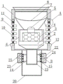
Fig. 1 is a schematic view of the overall structure of the present invention.
FIG. 2 is a schematic diagram of the structure at A in FIG. 1 according to the present invention.
FIG. 3 is a schematic diagram of the structure at B in FIG. 1 according to the present invention.
Fig. 4 is a schematic structural diagram of the housing of the present invention.
The reference signs are: 1. a housing; 2. a bearing plate; 3. a baffle plate; 4. a lamp fixing plate; 5. a bulb; 6. a protective frame; 7. an arc surface patch; 8. a glass sheet; 9. a heat dissipation hole of the lamp cap; 10. a dust-proof sheet; 11. opening a hole; 12. an adjusting block; 13. connecting blocks; 14. a first connecting column; 15. a support plate; 16. a second connecting column; 17. a connecting plate; 18. a clamping block; 19. a spring; 20. a barrel body; 21. a card slot; 22. a mounting frame; 23. pushing the plate; 24. a push rod; 25. and a support pillar.
Detailed Description
The technical solutions in the embodiments of the present invention will be clearly and completely described below with reference to the drawings in the embodiments of the present invention, and it is obvious that the described embodiments are only a part of the embodiments of the present invention, and not all of the embodiments. All other embodiments, which can be derived by a person skilled in the art from the embodiments given herein without making any creative effort, shall fall within the protection scope of the present invention.
The highlight LED flashlight lamp holder shown in the attached figures 1-4 comprises a shell 1, wherein a bearing plate 2 is arranged inside the shell 1, a baffle plate 3 is arranged at the top of the bearing plate 2, an electric lamp fixing plate 4 is arranged at the top of the baffle plate 3, a bulb 5 is arranged on the surface of the electric lamp fixing plate 4, a protection frame 6 is arranged at the top of the baffle plate 3, an arc surface sheet 7 is arranged at the top of the protection frame 6 and positioned outside the bulb 5, a glass sheet 8 is arranged at the top of the arc surface sheet 7 inside the shell 1, heat dissipation mechanisms are arranged at two ends of the shell 1, and clamping mechanisms are arranged at two ends of the bottom of the shell 1;
the heat dissipation mechanism comprises a plurality of lamp cap heat dissipation holes 9 arranged on the surface of the shell 1, the inner sides of the plurality of lamp cap heat dissipation holes 9 are provided with dustproof sheets 10, the surface of each dustproof sheet 10 is provided with a plurality of openings 11, and one end of the bottom of each dustproof sheet 10 is provided with an adjusting block 12;
clamping mechanism is including setting up connecting block 13 in 1 bottom of shell, connecting block 13 both ends are equipped with two first spliced poles 14, 14 one end of two first spliced poles is equipped with backup pad 15, 15 surfaces of backup pad are equipped with a plurality of second spliced poles 16, 16 outside connecting plates 17 that are equipped with of a plurality of second spliced poles, connecting plate 17 one end is equipped with fixture block 18, be equipped with spring 19 between connecting plate 17 and the backup pad 15, the both sides that are located connecting block 13 in 1 bottom of shell are equipped with stack shell 20, the inside draw-in groove 21 that is equipped with of stack shell 20, mounting bracket 22 is installed at 20 both ends of stack shell, the inside push pedal 23 that is equipped with of mounting bracket 22, push pedal 23 one end is equipped with push rod 24, the push pedal 23 other end is equipped with support post 25.
Further, the cross section of the bearing plate 2 is of an isosceles trapezoid structure, the bearing plate 2 is fixedly connected with the baffle 3, the cross section of the protection frame 6 is of a concave structure, and the protection frame 6 is fixedly connected with the baffle 3 so as to fix all parts inside the shell 1.
Furthermore, bulb 5 one end can be dismantled with electric light fixed plate 4 and be connected, cambered surface piece 7 and protective frame 6 fixed connection, glass piece 8 and shell 1 fixed connection to the light source that sends through bulb 5 jets out through glass piece 8 again after the reflection of cambered surface piece 7.
Furthermore, the two ends of the dustproof sheet 10 respectively extend into the two ends of the shell 1, and the adjusting block 12 is fixedly connected with the dustproof sheet 10, so that the position of the dustproof sheet 10 can be conveniently adjusted through the adjusting block 12, and the inside of the lamp holder is cooled and prevented from dust.
Further, connecting block 13 and shell 1 fixed connection, first spliced pole 14 both ends respectively with backup pad 15 and connecting block 13 fixed connection to in installation backup pad 15 and first spliced pole 14, make the structure more stable.
Further, second spliced pole 16 one end runs through connecting plate 17, and connecting plate 17 and second spliced pole 16 sliding connection, spring 19 both ends all with backup pad 15 and connecting plate 17 fixed connection to compress spring 19 through connecting plate 17 and second spliced pole 16 sliding connection.
Furthermore, the fixture block 18 is structurally matched with the clamping groove 21, the connecting plate 17 is fixedly connected with the fixture block 18, the barrel body 20 is movably connected with the shell 1 through the clamping groove 21 and the fixture block 18, and the mounting frame 22 is fixedly connected with the barrel body 20, so that the barrel body 20 and the shell 1 can be limited or disassembled through the fixture block 18 and the clamping groove 21.
Furthermore, one end of the push rod 24 extends to one end of the push plate 23, the push rod 24 is fixedly connected with the push plate 23, two ends of the push plate 23 are slidably connected with the mounting frame 22, one end of the abutting column 25 is fixedly connected with the push plate 23, and the abutting column 25 is parallel to the clamping block 18, so that the abutting column 25 is driven by the push plate 23 to push the clamping block 18 and keep away from the clamping groove 21.
The working principle of the invention is as follows: the invention transmits the light source to the glass sheet 8 through the arc surface sheet 7 and finally transmits the light source to the outside, so that the light source is maximized, the heat emitted by the bulb 5 is radiated through the lamp holder radiating holes 9 arranged at the two ends of the shell 1, meanwhile, the dustproof sheet 10 is arranged at the inner side of the lamp holder radiating holes 9 to prevent dust from entering the lamp holder, so as to avoid the damage of internal parts, the surface of the dustproof sheet 10 is provided with the opening 11 to radiate the heat emitted by the bulb 5, so as to play the effects of dust prevention and heat radiation, the opening 11 on the dustproof sheet 10 is adjusted through the adjusting block 12 to radiate or prevent dust, when the shell 1 is inserted into the barrel body 20 through the clamping block 18 in the clamping mechanism, because the connecting plate 17 is in sliding connection with the second connecting column 16, the clamping block 18 drives the connecting plate 17 to slide on the second connecting column 16, the spring 19 is compressed and stressed, because the clamping block 18 is matched with the clamping groove 21 structure, the clamping block 18 is more easily clamped into the clamping groove 21, when the clamping block 18 enters the clamping groove 21, the spring 19 releases pressure to enter the clamping groove 21, the barrel body 20 is in limited connection with the shell 1, when disassembly is needed, the push rod 24 is pushed, the push plate 23 drives the push plate 23 to be in sliding connection with the mounting frame 22, the abutting column 25 is arranged in parallel with the clamping block 18, and the abutting column 25 is fixedly connected with the push plate 23, so that the push plate 23 drives the abutting column 25 to move towards the clamping block 18, the abutting column 25 pushes the clamping block 18 out of the clamping groove 21, and the shell 1 and the barrel body 20 are disassembled.
The points to be finally explained are: first, in the description of the present application, it should be noted that, unless otherwise specified and limited, the terms "mounted," "connected," and "connected" should be understood broadly, and may be a mechanical connection or an electrical connection, or a communication between two elements, and may be a direct connection, and "upper," "lower," "left," and "right" are only used to indicate a relative positional relationship, and when the absolute position of the object to be described is changed, the relative positional relationship may be changed;
secondly, the method comprises the following steps: in the drawings of the disclosed embodiments of the invention, only the structures related to the disclosed embodiments are referred to, other structures can refer to common designs, and the same embodiment and different embodiments of the invention can be combined with each other without conflict;
and finally: the above description is only for the purpose of illustrating the preferred embodiments of the present invention and is not to be construed as limiting the invention, and any modifications, equivalents, improvements and the like that are within the spirit and principle of the present invention are intended to be included in the scope of the present invention.
Claims (8)
1. The utility model provides a highlight LED flashlight lamp holder, includes shell (1), its characterized in that: the lamp holder is characterized in that a receiving plate (2) is arranged inside the shell (1), a baffle plate (3) is arranged at the top of the receiving plate (2), an electric lamp fixing plate (4) is arranged at the top of the baffle plate (3), a bulb (5) is installed on the surface of the electric lamp fixing plate (4), a protection frame (6) is arranged at the top of the baffle plate (3), an arc surface sheet (7) is arranged at the top of the protection frame (6) and positioned outside the bulb (5), a glass sheet (8) is arranged at the top of the arc surface sheet (7) inside the shell (1), heat dissipation mechanisms are arranged at two ends of the shell (1), and clamping mechanisms are arranged at two ends of the bottom of the shell (1);
the heat dissipation mechanism comprises a plurality of lamp holder heat dissipation holes (9) arranged on the surface of the shell (1), the inner sides of the plurality of lamp holder heat dissipation holes (9) are provided with dustproof sheets (10), the surface of each dustproof sheet (10) is provided with a plurality of holes (11), and one end of the bottom of each dustproof sheet (10) is provided with an adjusting block (12);
the clamping mechanism comprises a connecting block (13) arranged at the bottom of a shell (1), two first connecting columns (14) are arranged at two ends of the connecting block (13), a supporting plate (15) is arranged at one end of each first connecting column (14), a plurality of second connecting columns (16) are arranged on the surface of the supporting plate (15), a connecting plate (17) is arranged outside each second connecting column (16), a clamping block (18) is arranged at one end of each connecting plate (17), a spring (19) is arranged between each connecting plate (17) and the corresponding supporting plate (15), barrel bodies (20) are arranged on two sides, located at the connecting block (13), of the bottom of the shell (1), clamping grooves (21) are formed in the barrel bodies (20), mounting frames (22) are installed at two ends of the barrel bodies (20), push plates (23) are arranged in the mounting frames (22), and push rods (24) are arranged at one ends of the push plates (23), the other end of the push plate (23) is provided with a support column (25).
2. A glare LED flashlight light head according to claim 1, wherein: the cross section of the bearing plate (2) is of an isosceles trapezoid structure, the bearing plate (2) is fixedly connected with the baffle (3), the cross section of the protection frame (6) is of a concave structure, and the protection frame (6) is fixedly connected with the baffle (3).
3. A glare LED flashlight light head according to claim 1, wherein: one end of the bulb (5) is detachably connected with the electric lamp fixing plate (4), the arc surface patch (7) is fixedly connected with the protection frame (6), and the glass sheet (8) is fixedly connected with the shell (1).
4. A glare LED flashlight light head according to claim 1, wherein: the dustproof sheet (10) is characterized in that two ends of the dustproof sheet (10) extend into two ends of the shell (1) respectively, and the adjusting block (12) is fixedly connected with the dustproof sheet (10).
5. A glare LED flashlight light head according to claim 1, wherein: connecting block (13) and shell (1) fixed connection, first spliced pole (14) both ends respectively with backup pad (15) and connecting block (13) fixed connection.
6. A glare LED flashlight light head according to claim 1, wherein: second spliced pole (16) one end runs through connecting plate (17), connecting plate (17) and second spliced pole (16) sliding connection, spring (19) both ends all with backup pad (15) and connecting plate (17) fixed connection.
7. A glare LED flashlight light head according to claim 1, wherein: the clamping block (18) is structurally matched with the clamping groove (21), the connecting plate (17) is fixedly connected with the clamping block (18), the barrel body (20) is movably connected with the shell (1) through the clamping groove (21) and the clamping block (18), and the mounting frame (22) is fixedly connected with the barrel body (20).
8. A glare LED flashlight light head according to claim 1, wherein: push rod (24) one end extends to push pedal (23) one end, just push rod (24) and push pedal (23) fixed connection, push pedal (23) both ends and mounting bracket (22) sliding connection, support post (25) one end and push pedal (23) fixed connection, support post (25) and fixture block (18) parallel arrangement.
Priority Applications (1)
| Application Number | Priority Date | Filing Date | Title |
|---|---|---|---|
| CN202011174477.3A CN114413193A (en) | 2020-10-28 | 2020-10-28 | Highlight LED flashlight lamp holder |
Applications Claiming Priority (1)
| Application Number | Priority Date | Filing Date | Title |
|---|---|---|---|
| CN202011174477.3A CN114413193A (en) | 2020-10-28 | 2020-10-28 | Highlight LED flashlight lamp holder |
Publications (1)
| Publication Number | Publication Date |
|---|---|
| CN114413193A true CN114413193A (en) | 2022-04-29 |
Family
ID=81260611
Family Applications (1)
| Application Number | Title | Priority Date | Filing Date |
|---|---|---|---|
| CN202011174477.3A Withdrawn CN114413193A (en) | 2020-10-28 | 2020-10-28 | Highlight LED flashlight lamp holder |
Country Status (1)
| Country | Link |
|---|---|
| CN (1) | CN114413193A (en) |
Cited By (1)
| Publication number | Priority date | Publication date | Assignee | Title |
|---|---|---|---|---|
| CN119022274A (en) * | 2024-10-30 | 2024-11-26 | 汕头市金亚发电子有限公司 | A waterproof floodlight and handheld illumination lamp capable of reducing battery aging |
-
2020
- 2020-10-28 CN CN202011174477.3A patent/CN114413193A/en not_active Withdrawn
Cited By (2)
| Publication number | Priority date | Publication date | Assignee | Title |
|---|---|---|---|---|
| CN119022274A (en) * | 2024-10-30 | 2024-11-26 | 汕头市金亚发电子有限公司 | A waterproof floodlight and handheld illumination lamp capable of reducing battery aging |
| CN119022274B (en) * | 2024-10-30 | 2025-01-17 | 汕头市金亚发电子有限公司 | Waterproof floodlight capable of reducing battery aging and handheld illuminating lamp |
Similar Documents
| Publication | Publication Date | Title |
|---|---|---|
| CN204328669U (en) | The reflector lamp device of convenient changing optical accessories | |
| CN218820045U (en) | Heat conduction device of LED lamp | |
| CN212510710U (en) | Studio lamp adjusting device | |
| CN212673013U (en) | Eye-protecting lamp simulating sunlight | |
| CN213983258U (en) | Make things convenient for reassembling type grille lamp | |
| CN115854299A (en) | Explosion-proof LED lamp and using method thereof | |
| CN222186726U (en) | LED lamp capable of being assembled rapidly | |
| CN214275516U (en) | Lighting lamp for building engineering | |
| CN220870709U (en) | Portable portable searchlight | |
| CN223622829U (en) | A novel LED flat panel light structure | |
| CN219756180U (en) | Embedded LED lighting lamp | |
| CN215216118U (en) | Combined LED projection lamp | |
| CN111981359A (en) | Spliced MINILED lamp backlight module | |
| CN223216189U (en) | An LED lamp cup that is easy to disassemble | |
| CN215061829U (en) | Automobile headlamp convenient for replacing radiating fins | |
| CN219976215U (en) | Car light convenient to overhaul | |
| CN216079493U (en) | Stage floodlight convenient to maintain | |
| CN221780599U (en) | A lighting fixture | |
| CN223228291U (en) | An LED lamp tube with a reflector | |
| CN216716103U (en) | Three-dimensional scanning light-filtering polarized lamp group | |
| CN224108110U (en) | A multifunctional modular combination panel light | |
| CN221121994U (en) | Novel projection lamp | |
| CN212961017U (en) | Fixing structure of lens in lamp | |
| CN223677644U (en) | A type of lamp | |
| CN219933861U (en) | Lamp convenient to maintain |
Legal Events
| Date | Code | Title | Description |
|---|---|---|---|
| PB01 | Publication | ||
| PB01 | Publication | ||
| WW01 | Invention patent application withdrawn after publication | ||
| WW01 | Invention patent application withdrawn after publication |
Application publication date: 20220429 |