Electroplating clamping device for production and processing of hollow parts of fitness equipment
Technical Field
The invention relates to the technical field of fitness equipment processing, in particular to an electroplating clamping device for production and processing of hollow parts of fitness equipment.
Background
The fitness is a sports item, which can enhance strength and flexibility, increase endurance, improve coordination and control the ability of each part of the body, thereby making the body strong, hollow parts with different specifications can be used in the production and processing of fitness equipment, and the surface of the hollow part is usually required to be electroplated for improving the wear resistance and corrosion resistance of the surface of the hollow part.
However, as for the electroplating clamping device for producing and processing the hollow parts of the traditional fitness equipment at present, the electroplating clamping device can only be applied to the requirement of supporting and fixing the hollow parts with a single inner diameter, cannot be adaptively adjusted according to the specification of the hollow parts, is high in use limitation, and can clamp and fix the hollow parts in a rigid clamping mode, so that the hollow parts are lack of flexible protection for the hollow parts, and are easily deformed due to the overlarge rigid clamping force, and the quality of the hollow parts is influenced.
Disclosure of Invention
In view of this, the invention provides an electroplating clamping device for production and processing of hollow parts of fitness equipment, which can better satisfy the supporting and fixing effects of hollow parts of different specifications by spacing distances between four movable rods according to the inner diameter of the hollow part, and applies thrust to a bottom rod through a clamping spring to keep an anti-slip rubber strip on the outer side of each movable rod in close fit with the inner side of the hollow part, thereby achieving a flexible clamping effect on the hollow part.
The invention provides an electroplating clamping device for production and processing of hollow parts of fitness equipment, which specifically comprises: fixing the top seat;
the bottom of the fixed top seat is connected with four support rods in a surrounding manner;
the movable base is positioned at the bottom of the fixed top seat, the top of the movable base is connected with four connecting rods in a surrounding manner, the connecting rods are connected with the support rods, and the movable base is connected with the fixed top seat through the connecting rods and the support rods;
the interior of the pull rod is hollow, the top of the pull rod is connected to the interior of the fixed top seat, and the bottom end of the pull rod is rotatably connected to the interior of the movable base;
the vaulting pole is provided with four altogether, and vaulting pole external connection has the centre gripping spring, and the vaulting pole bottom links to each other with the movable rod to the anti-skidding adhesive tape is installed in the movable rod outside.
Optionally, the top ends of the support rods are rotatably connected with the fixed top seat, the bottom ends of the connecting rods are rotatably connected with the movable base, and the top ends of the four connecting rods are rotatably connected with the four support rods respectively.
Optionally, a movable sliding hole is formed in the fixed top seat, and the top of the pull rod is slidably connected in the movable sliding hole in the fixed top seat.
Optionally, the two sides of the movable sliding hole in the fixed top seat are respectively provided with inverted internal teeth, the two sides of the pull rod are respectively provided with inverted external teeth, and the inverted external teeth on the outer side of the pull rod are meshed with the inverted internal teeth on the inner side of the movable sliding hole.
Optionally, sliding grooves are respectively formed in two sides of the movable sliding hole in the fixed top seat, the tooth grooves of the inverted inner teeth are communicated with the sliding grooves, and the inverted outer teeth on the outer side of the pull rod are connected in the sliding grooves in the movable sliding hole in a sliding mode.
Optionally, a return spring is sleeved outside the pull rod, the top end of the return spring is sleeved outside the bottom of the fixed top seat, and the bottom end of the return spring is sleeved outside the top of the movable base.
Optionally, the brace rod comprises:
the top end of the ejector rod is rotationally connected with the fixed ejector seat, the ejector rod is rotationally connected with the connecting rod, and an arc-shaped sliding hole is formed in the ejector rod;
the utility model provides a bottom bar, the bottom bar top is connected with the ejector pin bottom is rotated, and bottom bar and ejector pin turned angle are 0~120 degree, and the bottom bar outside is equipped with the arc slide bar, and arc slide bar sliding connection is in the arc slide hole.
Optionally, a clamping spring is sleeved outside the arc-shaped sliding rod, and the top end of the clamping spring is attached to the outer side of the ejector rod.
Optionally, the movable rod is connected with the bottom end of the support rod in a rotating mode, and a balancing weight is installed in the bottom end of the movable rod.
Advantageous effects
According to the electroplating clamping device provided by the embodiments of the invention, compared with the traditional electroplating clamping device, the distance between the four movable rods can be better satisfied with the supporting and fixing effects of hollow parts with different specifications according to the inner diameter of the hollow part, and the thrust is applied to the bottom rod through the clamping spring, so that the anti-skidding rubber strips on the outer sides of the movable rods and the inner sides of the hollow parts are kept in a close fit state, and the flexible clamping effect on the hollow parts is achieved.
In addition, through the setting of pull rod, according to cavity spare part internal diameter size, pulling pull rod top drives movable base through the pull rod and reciprocates, changes four movable rod spacing distances, makes the laminating of movable rod outside anti-skidding adhesive tape at cavity spare part inboard, supports fixedly to cavity spare part inboard, and the stability of guarantee cavity spare part electroplating processing man-hour, better satisfying supports fixed effect in different specification cavity spare parts.
In addition, due to the arrangement of the inverted outer teeth on the two sides of the pull rod, when the movable base stops moving, the inverted outer teeth on the outer side of the pull rod are fixed through the inverted inner teeth on the inner side of the movable sliding hole, so that the movable base is fixed through the pull rod, and the contact tightness between the anti-skidding rubber strips on the outer side of the movable rod and the inner side of the hollow part is guaranteed; and the setting of cooperation activity slide opening both sides spout, after the cavity spare part electroplating process finishes, rotate the pull rod top, make the pull rod outside fall the external tooth and separate with the inboard outer tooth that falls of activity slide opening, the pull rod outside falls the external tooth and is located the inboard spout of activity slide opening, can drive movable base through the pull rod and move down, reduces four movable rod interval distances, makes the outside anti-skidding adhesive tape of movable rod and the inboard separation of cavity spare part to take off the cavity spare part.
In addition, through reset spring's setting, when the pull rod outside is fallen the external tooth and is rotated to the inboard spout of activity slide opening in, reset spring applys thrust downwards to fixed footstock bottom movable base, and movable base drives four vaulting poles by oneself through the connecting rod and contracts to inside, and the inboard separation of movable rod outside anti-skidding adhesive tape and cavity spare part makes the cavity spare part tear open and get more simple and convenient swift by oneself.
In addition, through the setting of clamping spring, when the vaulting pole drives the movable rod and outwards expands, the sill bar receives cavity spare part reverse thrust to influence and inwards rotates, and clamping spring exerts thrust to the sill bar, makes movable rod outside anti-skidding adhesive tape and cavity spare part inboard keep closely the laminating state, plays the flexible centre gripping effect to cavity spare part, avoids the centre gripping dynamics too big, leads to cavity spare part to warp, influences cavity spare part quality.
Drawings
In order to more clearly illustrate the technical solutions of the embodiments of the present invention, the drawings of the embodiments will be briefly described below.
The drawings in the following description relate to some embodiments of the invention only and are not intended to limit the invention.
In the drawings:
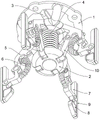
FIG. 1 shows a schematic top-axis side structure according to an embodiment of the invention;
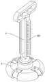
FIG. 2 shows a bottom-axis side structural schematic according to an embodiment of the invention;
FIG. 3 is a schematic view of a fixed top seat, a movable bottom seat and a pull rod connection structure according to an embodiment of the invention;
FIG. 4 shows a schematic cross-sectional view of a fixed top mount according to an embodiment of the invention;
FIG. 5 is a schematic view of a connection structure of a movable base and a pull rod according to an embodiment of the invention;
FIG. 6 is a schematic view of a strut to movable rod connection according to an embodiment of the present invention;
FIG. 7 illustrates a schematic view of a strut rotational adjustment arrangement according to an embodiment of the present invention;
fig. 8 shows a schematic diagram of a split structure of the top rod and the bottom rod according to the embodiment of the invention.
List of reference numerals
1. Fixing the top seat; 101. a movable slide hole; 1011. chamfering internal teeth; 1012. a chute;
2. a movable base;
3. a pull rod; 301. chamfering the outer teeth;
4. a return spring;
5. a stay bar; 501. a top rod; 5011. an arc-shaped slide hole; 502. a bottom bar; 5021. an arc-shaped sliding rod;
6. a clamping spring;
7. a movable rod;
8. a balancing weight;
9. an anti-slip rubber strip;
10. a connecting rod.
Detailed Description
In order to make the objects, aspects and advantages of the embodiments of the present invention more apparent, the embodiments of the present invention will be described in detail with reference to the accompanying drawings. Unless otherwise indicated, terms used herein have the ordinary meaning in the art. Like reference symbols in the various drawings indicate like elements.
The first embodiment is as follows:
please refer to fig. 1 to 8:
the invention provides an electroplating clamping device for producing and processing hollow parts of fitness equipment, which comprises: the device comprises a fixed top seat 1, a movable base 2 and a pull rod 3;
the bottom of the fixed top seat 1 is connected with four support rods 5 in a surrounding manner; the movable base 2 is positioned at the bottom of the fixed top seat 1, the top of the movable base 2 is connected with four connecting rods 10 in a surrounding manner, the connecting rods 10 are connected with the support rods 5, and the movable base 2 is connected with the fixed top seat 1 through the connecting rods 10 and the support rods 5; the interior of the pull rod 3 is hollow, the top of the pull rod 3 is connected to the interior of the fixed top seat 1, and the bottom end of the pull rod 3 is rotatably connected to the interior of the movable base 2; the number of the support rods 5 is four, the clamping springs 6 are connected to the outer portions of the support rods 5, the bottom ends of the support rods 5 are connected with the movable rods 7, and anti-skid rubber strips 9 are mounted on the outer sides of the movable rods 7; the top ends of the support rods 5 are rotatably connected with the fixed top seat 1, the bottom ends of the connecting rods 10 are rotatably connected with the movable base 2, and the top ends of the four connecting rods 10 are respectively rotatably connected with the four support rods 5; a movable sliding hole 101 is formed in the fixed top seat 1, the top of the pull rod 3 is connected in the movable sliding hole 101 in the fixed top seat 1 in a sliding manner, the top end of the pull rod 3 is pulled according to the inner diameter of the hollow part, the movable base 2 is driven to move up and down through the pull rod 3, the spacing distance of the four movable rods 7 is changed, and the supporting and fixing effect of the hollow parts with different specifications is better met; the movable rod 7 is connected with the bottom end of the support rod 5 in a rotating mode, the balancing weight 8 is installed in the bottom end of the movable rod 7, the balancing weight 8 is added to the bottom end of the movable rod 7, the movable rod 7 is enabled to be in a vertical state all the time, and the effect of attaching the anti-slip rubber strip 9 on the outer side of the movable rod 7 to the inner side of the hollow part is guaranteed.
In addition, according to the embodiment of the invention, the two sides of the movable sliding hole 101 in the fixed footstock 1 are respectively provided with the inverted inner teeth 1011, the two sides of the pull rod 3 are respectively provided with the inverted outer teeth 301, and the inverted outer teeth 301 on the outer side of the pull rod 3 are meshed with the inverted inner teeth 1011 on the inner side of the movable sliding hole 101;
adopt above-mentioned technical scheme, when activity base 2 stopped moving, fixed the pull rod 3 outside through the inboard tooth 1011 of falling of activity slide opening 101 and fall outer tooth 301 to fixing activity base 2 through pull rod 3, guarantee the compactness of the inboard contact of movable rod 7 outside anti-skidding adhesive tape 9 and cavity spare part.
In addition, according to the embodiment of the invention, the two sides of the movable sliding hole 101 in the fixed top seat 1 are respectively provided with the sliding grooves 1012, the tooth spaces of the inverted inner teeth 1011 are communicated with the sliding grooves 1012, and the inverted outer teeth 301 on the outer side of the pull rod 3 are slidably connected in the sliding grooves 1012 on the inner side of the movable sliding hole 101;
adopt above-mentioned technical scheme, treat that cavity spare part electroplating process finishes the back, rotate the 3 tops of pull rod, make 3 outside of pull rod fall outer tooth 301 and the inboard of activity slide opening 101 fall outer tooth 301 separation, 3 outside of pull rod fall outer tooth 301 be located the inboard spout 1012 of activity slide opening 101, can drive movable base 2 through pull rod 3 and move down, reduce four movable rod 7 intervals, make 7 outside of movable rod anti-skidding adhesive tape 9 and the inboard separation of cavity spare part, so that take off the cavity spare part.
In addition, according to the embodiment of the invention, the outside of the pull rod 3 is sleeved with the return spring 4, the top end of the return spring 4 is sleeved outside the bottom of the fixed top seat 1, and the bottom end of the return spring 4 is sleeved outside the top of the movable base 2;
adopt above-mentioned technical scheme, when 3 outsides of pull rod fall external tooth 301 and rotate to the inboard spout 1012 of activity slide opening 101 in, reset spring 4 applys thrust downwards to fixed footstock 1 bottom movable base 2, and movable base 2 drives four vaulting poles 5 by oneself through connecting rod 10 and contracts to inside, and the inboard separation of movable rod 7 outside anti-skidding adhesive tape 9 and cavity spare part makes the cavity spare part tear open and get more simple and convenient swift.
Example two:
the stay bar 5 includes: a top bar 501 and a bottom bar 502;
the top end of the ejector rod 501 is rotatably connected with the fixed ejector base 1, the ejector rod 501 is rotatably connected with the connecting rod 10, and an arc-shaped sliding hole 5011 is formed in the ejector rod 501;
the top of the bottom rod 502 is rotatably connected with the bottom end of the top rod 501, the rotating angle between the bottom rod 502 and the top rod 501 is 0-120 degrees, an arc-shaped sliding rod 5021 is arranged on the outer side of the bottom rod 502, the arc-shaped sliding rod 5021 is slidably connected into an arc-shaped sliding hole 5011, a clamping spring 6 is sleeved outside the arc-shaped sliding rod 5021, and the top end of the clamping spring 6 is attached to the outer side of the top rod 501;
adopt above-mentioned technical scheme, when vaulting pole 5 drove the outside expansion of movable rod 7, the sill bar 502 receives cavity spare part reverse thrust to influence and inwards rotates, and clamping spring 6 exerts thrust to sill bar 502, makes the 7 outside anti-skidding adhesive tape 9 of movable rod and cavity spare part inboard keep closely the laminating state, plays to the flexible centre gripping effect of cavity spare part, avoids the centre gripping dynamics too big, leads to cavity spare part to warp, influences cavity spare part quality.
The specific use mode and function of the embodiment are as follows: when the anti-skid device is used, the top end of the pull rod 3 is pulled, the movable base 2 is driven to move upwards through the pull rod 3, the movable base 2 drives the four support rods 5 to expand outwards through the connecting rod 10, the spacing distance between the four movable rods 7 is increased, and the anti-skid rubber strips 9 on the outer sides of the movable rods 7 are attached to the inner sides of hollow parts; the bottom rod 502 rotates inwards under the influence of the reverse thrust of the hollow part, the clamping spring 6 applies thrust to the bottom rod 502, so that the anti-skid rubber strip 9 on the outer side of the movable rod 7 is tightly attached to the inner side of the hollow part, and the flexible clamping effect on the hollow part is achieved; when the movable base 2 stops moving, the reverse outer teeth 301 on the outer side of the pull rod 3 are fixed through the reverse inner teeth 1011 on the inner side of the movable sliding hole 101, so that the movable base 2 is fixed through the pull rod 3, the contact tightness between the anti-skidding rubber strip 9 on the outer side of the movable rod 7 and the inner side of the hollow part is guaranteed, and the fixed hollow part can be subjected to electroplating processing; after the electroplating treatment of the hollow part is finished, the top end of the pull rod 3 is rotated, the outer inverted tooth 301 on the outer side of the pull rod 3 is separated from the inner inverted tooth 301 on the inner side of the movable sliding hole 101, the outer inverted tooth 301 on the outer side of the pull rod 3 is located in the inner sliding groove 1012 on the inner side of the movable sliding hole 101, the reset spring 4 applies downward thrust to the movable base 2 at the bottom of the fixed top seat 1, the movable base 2 automatically drives the four support rods 5 to contract towards the inside through the connecting rod 10, and the anti-slip rubber strip 9 on the outer side of the movable rod 7 automatically separates from the inner side of the hollow part, so that the hollow part can be detached.
Finally, it should be noted that, when describing the positions of the components and the matching relationship therebetween, the present invention is usually illustrated by one/a pair of components, however, it should be understood by those skilled in the art that such positions, matching relationship, etc. are also applicable to other/other pairs of components.
The above description is intended to be illustrative of the present invention and not to limit the scope of the invention, which is defined by the claims appended hereto.