CN114380471B - Automatic water environment treatment and purification equipment based on microorganism nest - Google Patents
Automatic water environment treatment and purification equipment based on microorganism nest Download PDFInfo
- Publication number
- CN114380471B CN114380471B CN202210144946.XA CN202210144946A CN114380471B CN 114380471 B CN114380471 B CN 114380471B CN 202210144946 A CN202210144946 A CN 202210144946A CN 114380471 B CN114380471 B CN 114380471B
- Authority
- CN
- China
- Prior art keywords
- pipe
- helical gear
- annular groove
- sealing plate
- water tank
- Prior art date
- Legal status (The legal status is an assumption and is not a legal conclusion. Google has not performed a legal analysis and makes no representation as to the accuracy of the status listed.)
- Active
Links
- XLYOFNOQVPJJNP-UHFFFAOYSA-N water Substances O XLYOFNOQVPJJNP-UHFFFAOYSA-N 0.000 title claims abstract description 61
- 244000005700 microbiome Species 0.000 title claims abstract description 21
- 238000000746 purification Methods 0.000 title claims abstract description 19
- 238000007789 sealing Methods 0.000 claims abstract description 49
- 238000001914 filtration Methods 0.000 claims abstract description 46
- 230000007246 mechanism Effects 0.000 claims abstract description 36
- 230000005540 biological transmission Effects 0.000 claims abstract description 24
- 238000004140 cleaning Methods 0.000 claims abstract description 17
- 230000007704 transition Effects 0.000 claims abstract description 12
- 230000002457 bidirectional effect Effects 0.000 claims description 18
- 230000000813 microbial effect Effects 0.000 claims description 6
- 238000005352 clarification Methods 0.000 claims description 2
- 230000000694 effects Effects 0.000 abstract description 22
- 239000010865 sewage Substances 0.000 abstract description 7
- 238000007599 discharging Methods 0.000 abstract description 6
- 230000000903 blocking effect Effects 0.000 abstract description 3
- 239000007921 spray Substances 0.000 description 5
- 230000006872 improvement Effects 0.000 description 3
- 238000009434 installation Methods 0.000 description 3
- 238000005406 washing Methods 0.000 description 3
- 235000017166 Bambusa arundinacea Nutrition 0.000 description 2
- 235000017491 Bambusa tulda Nutrition 0.000 description 2
- 241001330002 Bambuseae Species 0.000 description 2
- 235000015334 Phyllostachys viridis Nutrition 0.000 description 2
- 230000009471 action Effects 0.000 description 2
- 239000011425 bamboo Substances 0.000 description 2
- 239000000463 material Substances 0.000 description 2
- 238000003809 water extraction Methods 0.000 description 2
- 241000196324 Embryophyta Species 0.000 description 1
- 230000009286 beneficial effect Effects 0.000 description 1
- 238000005202 decontamination Methods 0.000 description 1
- 230000003588 decontaminative effect Effects 0.000 description 1
- 238000005516 engineering process Methods 0.000 description 1
- 230000004048 modification Effects 0.000 description 1
- 238000012986 modification Methods 0.000 description 1
- 238000005457 optimization Methods 0.000 description 1
- 238000006467 substitution reaction Methods 0.000 description 1
Images


Classifications
-
- C—CHEMISTRY; METALLURGY
- C02—TREATMENT OF WATER, WASTE WATER, SEWAGE, OR SLUDGE
- C02F—TREATMENT OF WATER, WASTE WATER, SEWAGE, OR SLUDGE
- C02F3/00—Biological treatment of water, waste water, or sewage
- C02F3/34—Biological treatment of water, waste water, or sewage characterised by the microorganisms used
-
- C—CHEMISTRY; METALLURGY
- C02—TREATMENT OF WATER, WASTE WATER, SEWAGE, OR SLUDGE
- C02F—TREATMENT OF WATER, WASTE WATER, SEWAGE, OR SLUDGE
- C02F1/00—Treatment of water, waste water, or sewage
- C02F1/001—Processes for the treatment of water whereby the filtration technique is of importance
-
- C—CHEMISTRY; METALLURGY
- C02—TREATMENT OF WATER, WASTE WATER, SEWAGE, OR SLUDGE
- C02F—TREATMENT OF WATER, WASTE WATER, SEWAGE, OR SLUDGE
- C02F2303/00—Specific treatment goals
- C02F2303/16—Regeneration of sorbents, filters
-
- Y—GENERAL TAGGING OF NEW TECHNOLOGICAL DEVELOPMENTS; GENERAL TAGGING OF CROSS-SECTIONAL TECHNOLOGIES SPANNING OVER SEVERAL SECTIONS OF THE IPC; TECHNICAL SUBJECTS COVERED BY FORMER USPC CROSS-REFERENCE ART COLLECTIONS [XRACs] AND DIGESTS
- Y02—TECHNOLOGIES OR APPLICATIONS FOR MITIGATION OR ADAPTATION AGAINST CLIMATE CHANGE
- Y02W—CLIMATE CHANGE MITIGATION TECHNOLOGIES RELATED TO WASTEWATER TREATMENT OR WASTE MANAGEMENT
- Y02W10/00—Technologies for wastewater treatment
- Y02W10/10—Biological treatment of water, waste water, or sewage
Landscapes
- Life Sciences & Earth Sciences (AREA)
- Microbiology (AREA)
- Hydrology & Water Resources (AREA)
- Engineering & Computer Science (AREA)
- Environmental & Geological Engineering (AREA)
- Water Supply & Treatment (AREA)
- Chemical & Material Sciences (AREA)
- Organic Chemistry (AREA)
- Biodiversity & Conservation Biology (AREA)
- Filtration Of Liquid (AREA)
Abstract
The invention discloses automatic water environment treatment and purification equipment based on a microorganism nest, and relates to the technical field of sewage treatment. The invention enables the filtering annular groove at one end of the middle pipe to be exchanged by one hundred eighty degrees by starting the transmission mechanism, simultaneously the first sealing plate at the same side is completely closed, the second sealing plate is opened, and the structures symmetrical to the structures are in corresponding and opposite states, so that when the filtering annular groove at one end is blocked, the filtering annular groove at the other end is used, the filtering annular groove is blocked by utilizing the function of the cleaning mechanism to complete cleaning of the filtering annular groove, and the blocking object falls to the residue collecting box along the transition box and the first discharging pipe to complete collection and treatment of garbage, so that the whole equipment is still started while the filtering annular groove is cleaned, and the purification effect of the equipment is greatly improved.
Description
Technical Field
The invention relates to the technical field of sewage treatment, in particular to automatic water environment treatment and purification equipment based on a microorganism nest.
Background
With the increasing emphasis of the state on the ecological environment, the water environment treatment idea gradually changes from the original black and odorous water treatment to water quality improvement, water ecology improvement and water resource optimization, so that the water environment treatment industry is required to continuously update the existing water treatment technology to meet the requirement of higher standard, and a water purifier is used for filtration and purification at present; the filter screen is generally designed in the existing water purifier, so that the existing water purifier is easy to block during use, the phenomenon of poor water purifying effect is caused, and the purifying effect is reduced.
Disclosure of Invention
Based on the above, the invention aims to provide an automatic water environment treatment and purification device based on a microorganism nest, so as to solve the technical problem that in the prior art, generally, a filter screen is designed, so that blockage is easy to occur during use, the water body purification effect is poor, and the purification effect is reduced.
In order to achieve the purpose, the invention provides the following technical scheme: the utility model provides an automatic water environment improvement clarification plant based on microorganism nest, includes mounting bracket, intermediate pipe, mounting panel, residue collecting box, water tank and microorganism purifying box, the outside of intermediate pipe symmetry intercommunication has second unloading pipe and pass-through box respectively, the bottom of pass-through box all communicates there is first unloading pipe, the outside of second unloading pipe all cooperatees with the mounting panel, the inside of first unloading pipe and second unloading pipe all is provided with second closing plate and the first closing plate of mutually supporting, and corresponds and be connected with first rotation axis and second rotation axis respectively between two sets of second closing plate and the first closing plate, the inside of intermediate pipe is provided with middle section of thick bamboo, and the inside of middle section of thick bamboo is provided with wiper mechanism, the inside of intermediate pipe symmetry is provided with the annular chute with first unloading pipe matched with respectively, the inside of annular chute is provided with corresponding filtration annular groove respectively, the inside of mounting bracket is provided with drive mechanism, and the mounting bracket mutually supports with filtration annular groove, first rotation axis and second rotation axis respectively through drive mechanism.
Through adopting above-mentioned technical scheme, utilize and start drive mechanism, make the filtration annular groove that drives intermediate bottom one end carry out one hundred eighty degrees and exchange, the first closing plate of homonymy is thoroughly closed simultaneously, and the second closing plate is opened, and with the structure of above-mentioned structure symmetry, all be corresponding state of turning over each other, thereby when the filtration annular groove of one end takes place to block up, the filtration annular groove of the other end begins to use, and take place to block up the effect of filtering the annular groove and utilizing wiper mechanism, the completion is to the washing of filtering the annular groove, and make the plug fall to the residue collecting box along transition case and first unloading pipe, the completion is to the collection and the processing of rubbish, through above-mentioned mechanism, make when wasing the filtration annular groove, whole equipment still starts, thereby improve the purifying effect of this equipment greatly.
The invention is further arranged in that a first connecting pipe is communicated between two ends of the middle pipe and the water tank, and the top of the water tank is connected with the cleaning mechanism.
Through adopting above-mentioned technical scheme to in with intermediate pipe filterable water along first connecting pipe flow direction water tank, accomplish the transport of crossing water, so that work.
The cleaning mechanism further comprises a pump body, a second connecting pipe, conveying pipes and a spray head, wherein the pump body is arranged at the top of the water tank, the second connecting pipe extending to the inner side of the mounting frame is arranged at the output end of the pump body, one end of the second connecting pipe is respectively communicated with the two symmetrical conveying pipes, and one end of each conveying pipe is communicated with the spray head.
Through adopting above-mentioned technical scheme, utilize the effect of the pump body, with the water extraction in the water tank and along the second connecting pipe enter into the conveyer pipe, erupt by the shower nozzle at last, accomplish and wash the stable work of being convenient for.
The invention is further arranged in that the transmission mechanism comprises a bidirectional transmission case, and the output end of the bidirectional transmission case is respectively provided with a first helical gear and a third helical gear.
Through adopting above-mentioned technical scheme, utilize the effect of two-way transmission case, be convenient for provide kinetic energy for equipment, the transmission of power is accomplished in the effect of cooperation first helical gear and third helical gear, the equipment normal operating of being convenient for.
The invention is further arranged in such a way that the transmission mechanism further comprises a second helical gear, a fourth helical gear, a sealing slide seat, a bidirectional helical gear column and a fifth helical gear, the second helical gear and the fifth helical gear are respectively arranged at the outer sides of the first rotating shaft and the second rotating shaft, the sealing slide seats are respectively arranged at two ends of the filtering annular groove, the fourth helical gear is arranged at the outer side of one group of sealing slide seats, the bidirectional helical gear column matched with the fourth helical gear is rotatably connected inside the mounting frame, and the second helical gear and the fifth helical gear are respectively meshed with the first helical gear and the bidirectional helical gear column.
Through adopting above-mentioned technical scheme, utilize under the mutually supporting of second helical gear, fourth helical gear, sealed slide, two-way helical gear post and fifth helical gear, correspond the position switching with first closing plate, second closing plate and filtration ring channel to go on of work.
The invention is further provided that an installation box is arranged in the middle of the installation plate, and the interior of the installation box is matched with the fifth bevel gear.
Through adopting above-mentioned technical scheme, utilize the effect of install bin, be convenient for effectively install fifth helical gear, guarantee the normal operating of fifth helical gear.
The invention is further provided that the top of the mounting rack is provided with a microorganism purification box which is mutually communicated with the second blanking pipe. And the outer sides of the water tanks are respectively communicated with water outlet pipes.
Through adopting above-mentioned technical scheme, utilize the effect of microorganism purifying box to be convenient for to the cultivation of microorganism, improve equipment's purifying effect.
The invention is further set that a plurality of groups of culture areas are uniformly arranged at the top end in the microorganism purification box.
Through adopting above-mentioned technical scheme, utilize the effect in multiunit culture area to guarantee can cultivate multiple microorganism, with this purifying effect that further improves equipment.
The two groups of second sealing plates and the first sealing plates are designed in a corresponding crossing state respectively, and the second sealing plates and the first sealing plates on the same side are designed in a crossing state.
By adopting the technical scheme, the working states of the second sealing plate and the first sealing plate on the same side are opposite, and the corresponding working states of the second sealing plate and the first sealing plate on the same group are opposite, so that the work is convenient to carry out.
In summary, the invention mainly has the following beneficial effects: when the garbage collection and treatment device is used, the transmission mechanism is started, so that the filtering annular groove at one end of the middle pipe is driven to be subjected to one-hundred-eighty degree exchange, the first sealing plate at the same side is completely closed, the second sealing plate is opened, and the filtering annular groove is symmetrical to the structure and is in a corresponding and mutually inverted state, so that when the filtering annular groove at one end is blocked, the filtering annular groove at the other end is used, the filtering annular groove is cleaned under the action of the cleaning mechanism, a blockage object falls to the residue collection box along the transition box and the first blanking pipe, the garbage collection and treatment are finished, and through the mechanism, the whole device is still started while the filtering annular groove is cleaned, so that the purification effect of the device is greatly improved.
Drawings
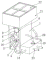
FIG. 1 is a schematic structural view of the present invention;
FIG. 2 is a first perspective cross-sectional view of the present invention;
FIG. 3 is an enlarged view taken at A of FIG. 2 in accordance with the present invention;
FIG. 4 is an enlarged view taken at B of FIG. 2 in accordance with the present invention;
FIG. 5 is another perspective sectional view of the present invention;
fig. 6 is an enlarged view of the invention at C in fig. 5.
In the figure: 1. a mounting frame; 2. an intermediate pipe; 3. a transition box; 4. a first blanking pipe; 5. a residue collection box; 6. a transmission mechanism; 601. a bidirectional transmission case; 602. a first helical gear; 603. a second helical gear; 604. a third bevel gear; 605. a fourth helical gear; 606. a sealing slide seat; 607. a bidirectional bevel gear column; 608. a fifth helical gear; 7. filtering the annular groove; 8. a second blanking pipe; 9. mounting a plate; 10. a first rotating shaft; 11. a first sealing plate; 12. a second rotation shaft; 13. an intermediate cylinder; 14. an annular chute; 15. installing a box; 16. a first connecting pipe; 17. a second sealing plate; 18. a water tank; 19. a pump body; 20. a second connecting pipe; 21. a microbial decontamination chamber; 22. a culture zone; 23. a water outlet pipe; 24. a delivery pipe; 25. and (4) a spray head.
Detailed Description
The technical solution in the embodiments of the present invention will be clearly and completely described below with reference to the accompanying drawings in the embodiments of the present invention. The embodiments described below with reference to the accompanying drawings are illustrative only for the purpose of explaining the present invention, and are not to be construed as limiting the present invention.
The following describes an embodiment of the present invention based on its overall structure.
An automatic water environment treatment and purification device based on a microorganism nest is disclosed, as shown in fig. 1-6, and comprises a mounting frame 1, a middle pipe 2, a mounting plate 9, a residue collecting box 5, a water tank 18 and a microorganism purifying box 21, the completeness of the device is ensured, the outer side of the middle pipe 2 is respectively and symmetrically communicated with a second blanking pipe 8 and a transition box 3, the bottom of the transition box 3 is communicated with a first blanking pipe 4, the outer side of the second blanking pipe 8 is matched with the mounting plate 9, a transmission mechanism 6 is arranged inside the mounting frame 1, the transmission mechanism 6 is started to drive a filtering annular groove 7 at one end of the middle pipe 2 to be exchanged by one hundred eighty degrees, a second sealing plate 17 and a first sealing plate 11 which are matched with each other are arranged inside the first blanking pipe 4 and the second blanking pipe 8, and a first rotating shaft 10 and a second rotating shaft 12 are respectively connected between the corresponding two groups of second sealing plates 17 and the first sealing plates 11, meanwhile, the first sealing plate 11 on the same side is completely closed, the second sealing plate 17 is opened, and the structures symmetrical to the above structures are all in a corresponding reverse state, the middle tube 2 is internally provided with a middle cylinder 13, the middle cylinder 13 is internally provided with a cleaning mechanism, the middle tube 2 is internally and symmetrically provided with annular chutes 14 matched with the first discharging tube 4, the annular chutes 14 are internally and respectively provided with corresponding filtering annular grooves 7, the mounting frame 1 is respectively matched with the filtering annular grooves 7, the first rotating shaft 10 and the second rotating shaft 12 through a transmission mechanism 6, when the filtering annular groove 7 at one end is blocked, the filtering annular groove 7 at the other end is used, and the blocked filtering annular groove 7 utilizes the cleaning mechanism to complete cleaning of the filtering annular groove 7, and the blocking object falls to the residue collecting box 5 along the transition box 3 and the first discharging tube 4, the completion is to the collection and the processing of rubbish for when wasing filter ring groove 7, whole equipment still starts through above-mentioned mechanism, thereby improves the purifying effect of this equipment greatly.
Referring to fig. 1, a first connecting pipe 16 is connected between two ends of the middle pipe 2 and the water tank 18, and the top of the water tank 18 is connected to a cleaning mechanism, so that the filtered water in the middle pipe 2 flows into the water tank 18 along the first connecting pipe 16, and the filtered water is delivered to work.
Please refer to fig. 1, the cleaning mechanism includes the pump body 19, the second connecting pipe 20, conveyer pipe 24 and shower nozzle 25, the pump body 19 is installed at the top of water tank 18, utilize the effect of the pump body 19, the output of the pump body 19 is provided with the second connecting pipe 20 that extends to the mounting bracket 1 inboard, the one end of second connecting pipe 20 communicates respectively has two conveyer pipes 24 of symmetry, and the one end of conveyer pipe 24 all communicates there is the shower nozzle 25, with the water extraction in the water tank 18 and along the second connecting pipe 20 enter into the conveyer pipe 24, spray by shower nozzle 25 at last, accomplish the washing, be convenient for stable work.
Referring to fig. 2, 3, 4, 5 and 6, the transmission mechanism 6 includes a bidirectional transmission case 601, the output end of the bidirectional transmission case 601 is respectively provided with a first helical gear 602 and a third helical gear 604 to provide kinetic energy for the equipment, and the transmission of force is completed by matching the action of the first helical gear 602 and the third helical gear 604 to facilitate the normal operation of the equipment, the transmission mechanism 6 further includes a second helical gear 603, a fourth helical gear 605, a sealing sliding seat 606, a bidirectional helical gear column 607 and a fifth helical gear 608, the second helical gear 603 and the fifth helical gear 608 are respectively arranged at the outer sides of the first rotating shaft 10 and the second rotating shaft 12, the two ends of the filtering annular groove 7 are both provided with the sealing sliding seats 606, the outer side of one set of the sealing sliding seats 606 is provided with the fourth helical gear 605, the inner portion of the mounting frame 1 is rotatably connected with the bidirectional helical gear column 607 matched with the fourth helical gear, and the second helical gear 603 and the fifth helical gear 608 are respectively engaged with the first helical gear 602 and the bidirectional helical gear column 607 to facilitate the switching of the sealing plate 17 and the filtering annular groove 7 for the operation.
Referring to fig. 2, the mounting box 15 is disposed in the middle of the mounting plate 9, so that the fifth bevel gear 608 can be mounted effectively, the normal operation of the fifth bevel gear 608 is ensured, and the interior of the mounting box 15 is matched with the fifth bevel gear 608 to ensure the normal operation of the apparatus.
Referring to fig. 1, a microorganism purifying box 21 communicated with the second feeding pipe 8 is disposed on the top of the mounting frame 1, the microorganism is cultured conveniently by the microorganism purifying box 21, the purifying effect of the device is improved, and water outlet pipes 23 are respectively communicated with the outer sides of the water tanks 18 to facilitate water drainage.
Referring to fig. 1, a plurality of groups of culture areas 22 are uniformly disposed at the top end of the interior of the microorganism purification box 21, and the plurality of groups of culture areas 22 are used to ensure that a plurality of microorganisms can be cultured, thereby further improving the purification effect of the device.
Referring to fig. 2, the two sets of second sealing plates 17 and the first sealing plate 11 are designed to be in a cross state, and the second sealing plate 17 and the first sealing plate 11 on the same side are designed to be in a cross state, so that the second sealing plate 17 and the first sealing plate 11 on the same side are ensured to be in an opposite working state, and the second sealing plate 17 and the first sealing plate 11 on the same group are in an opposite working state, thereby facilitating the working.
The working principle of the invention is as follows: when the device is used, sewage flows into the microbial purification box 21, a plurality of groups of culture areas 22 in the microbial purification box 21 are used for microbial evolution, so that a water body is initially evolved, then the sewage enters the middle pipe 2 along a group of second discharging pipes 8 and passes through the filtering annular groove 7, then the sewage enters the water tank 18 along the first connecting pipe 16, and water in the water tank 18 is discharged along the water outlet pipe 23, so that the sewage is purified;
then when a group of filtering annular grooves 7 are blocked, a transmission mechanism 6, specifically a bidirectional transmission box 601 is started to drive a first helical gear 602 and a third helical gear 604 respectively, because the first helical gear 602 and the third helical gear 604 are meshed with a second helical gear 603 and a fourth helical gear 605 respectively, and the fourth helical gear 605 and a fifth helical gear 608 are meshed with a bidirectional helical gear column 607, the states of a first sealing plate 11, the filtering annular groove 7 and a second sealing plate 17 on the same side are correspondingly changed respectively, sewage enters the other end of the intermediate pipe 2 along another group of second discharging pipes 8, enters the water tank 18 along the corresponding first connecting pipes 16, is finally discharged, meanwhile, the blocked filtering annular groove 7 rotates to the transition box 3, a cleaning mechanism is started, specifically a pump body 19 enters water in the water tank 18 along the second connecting pipes 20, finally, water is sprayed out from the corresponding spray heads 25 to the filtering annular groove 7, and then the blocking material enters the residue collecting box 5 along the transition box 3 and the residue collecting box 5 to filter residue discharging water outlet; cleaning and collecting are completed; thereby when taking place to block up as the filtration annular groove 7 of one end, the filtration annular groove 7 of the other end begins to use, and take place to block up filtration annular groove 7 and utilize wiper mechanism's effect, accomplish the washing to filtering annular groove 7, and make the plug along transition case 3 and first unloading pipe 4 whereabouts to residue collecting box 5, accomplish the collection and the processing to rubbish, through above-mentioned mechanism, make when wasing filtration annular groove 7, whole equipment still starts, thereby improve the purifying effect of this equipment greatly.
Although embodiments of this invention have been shown and described, it is to be understood that such embodiments are merely illustrative of and not restrictive on the broad invention, and that any one or more of the described features, structures, materials, or characteristics may be combined in any suitable manner in any one or more embodiments or examples, and that modifications, substitutions, and variations that do not materially contribute to the novel teachings of this invention may be made by those skilled in the art after reading this disclosure without departing from the principles and spirit of this invention, but within the scope of the appended claims.
Claims (1)
1. The utility model provides a clarification plant is administered to automatic water environment based on microorganism nest, includes mounting bracket (1), intermediate pipe (2), mounting panel (9), residue collecting box (5), water tank (18) and microorganism purifying box (21), its characterized in that: the outer side of the middle pipe (2) is symmetrically communicated with a second blanking pipe (8) and a transition box (3) respectively, the bottom of the transition box (3) is communicated with a first blanking pipe (4), the outer side of the second blanking pipe (8) is matched with a mounting plate (9), a second sealing plate (17) and a first sealing plate (11) which are matched with each other are arranged inside the first blanking pipe (4) and the second blanking pipe (8) respectively, a first rotating shaft (10) and a second rotating shaft (12) are connected between the two groups of second sealing plates (17) and the first sealing plate (11) correspondingly, a middle cylinder (13) is arranged inside the middle pipe (2), a cleaning mechanism is arranged inside the middle cylinder (13), annular sliding grooves (14) which are matched with the first blanking pipe (4) are symmetrically arranged inside the middle pipe (2) respectively, corresponding filtering annular grooves (7) are arranged inside the annular sliding grooves (14) respectively, a transmission mechanism (6) is arranged inside the middle pipe (1), the transmission mechanism (6) comprises a bidirectional transmission box (601), a second bevel gear (602) and a third bevel gear (604), and a second bevel gear (601) respectively, A fourth helical gear (605), a sealing sliding seat (606), a bidirectional helical gear column (607) and a fifth helical gear (608), wherein the second helical gear (603) and the fifth helical gear (608) are respectively arranged at the outer sides of the first rotating shaft (10) and the second rotating shaft (12), the two ends of the filtering annular groove (7) are both provided with the sealing sliding seat (606), the outer side of the sealing sliding seat (606) is provided with the fourth helical gear (605), the mounting frame (1) is rotatably connected with the bidirectional helical gear column (607) matched with the fourth helical gear (605), the second helical gear (603) and the fifth helical gear (608) are respectively engaged with the first helical gear (602) and the bidirectional helical gear column (607), the mounting frame (1) is respectively matched with the filtering annular groove (7), the first rotating shaft (10) and the second rotating shaft (12) through a transmission mechanism (6), the second sealing plate (17) and the first sealing plate (11) are respectively designed in a cross state, the second sealing plate (17) and the first sealing plate (11) are designed in a cross state, the top of the water tank (18) is connected with a cleaning connection pipe (18), and a cleaning mechanism (18) is designed in a cross state, and a water tank (18) is connected with a water tank (18) connected with a cleaning mechanism (18) connected with a cleaning connection pipe connecting pipe (18) connected with a water tank (18) connected with the pump body (18), and a water tank (18) in a set, second connecting pipe (20), conveyer pipe (24) and shower nozzle (25), the top at water tank (18) is installed in pump body (19), the output of pump body (19) is provided with second connecting pipe (20) that extend to mounting bracket (1) inboard, the one end of second connecting pipe (20) communicates respectively has two conveyer pipes (24) of symmetry, and the one end of conveyer pipe (24) all communicates shower nozzle (25), the centre department of mounting panel (9) is provided with install bin (15), mutually supports between the inside of its install bin (15) and fifth helical gear (608), the top of mounting bracket (1) is provided with microbial purification case (21) that communicate each other with second unloading pipe (8), the outside of water tank (18) communicates respectively has outlet pipe (23), the inside top of microbial purification case (21) evenly is provided with multiunit culture area (22).
Priority Applications (1)
| Application Number | Priority Date | Filing Date | Title |
|---|---|---|---|
| CN202210144946.XA CN114380471B (en) | 2022-02-17 | 2022-02-17 | Automatic water environment treatment and purification equipment based on microorganism nest |
Applications Claiming Priority (1)
| Application Number | Priority Date | Filing Date | Title |
|---|---|---|---|
| CN202210144946.XA CN114380471B (en) | 2022-02-17 | 2022-02-17 | Automatic water environment treatment and purification equipment based on microorganism nest |
Publications (2)
| Publication Number | Publication Date |
|---|---|
| CN114380471A CN114380471A (en) | 2022-04-22 |
| CN114380471B true CN114380471B (en) | 2023-04-07 |
Family
ID=81206177
Family Applications (1)
| Application Number | Title | Priority Date | Filing Date |
|---|---|---|---|
| CN202210144946.XA Active CN114380471B (en) | 2022-02-17 | 2022-02-17 | Automatic water environment treatment and purification equipment based on microorganism nest |
Country Status (1)
| Country | Link |
|---|---|
| CN (1) | CN114380471B (en) |
Family Cites Families (5)
| Publication number | Priority date | Publication date | Assignee | Title |
|---|---|---|---|---|
| JP2001000992A (en) * | 1999-06-21 | 2001-01-09 | Matsushita Electric Ind Co Ltd | Wastewater treatment equipment |
| JP2007111688A (en) * | 2005-10-18 | 2007-05-10 | Teru Kagaku Kogyo Kk | Method of purifying miscellaneous drainage and apparatus for the same |
| CN113149365B (en) * | 2021-05-08 | 2022-06-17 | 河北恒特环保工程有限公司 | Automatic water environment treatment and purification equipment based on microorganism nest |
| CN113233632A (en) * | 2021-06-05 | 2021-08-10 | 广东博地环境工程有限公司 | Environment-friendly landfill leachate treatment equipment and method thereof |
| CN113877280A (en) * | 2021-10-15 | 2022-01-04 | 温州中伟石化设备制造有限公司 | Filter screen auto-change over device of Y type filter |
-
2022
- 2022-02-17 CN CN202210144946.XA patent/CN114380471B/en active Active
Also Published As
| Publication number | Publication date |
|---|---|
| CN114380471A (en) | 2022-04-22 |
Similar Documents
| Publication | Publication Date | Title |
|---|---|---|
| CN113149365B (en) | Automatic water environment treatment and purification equipment based on microorganism nest | |
| CN211546055U (en) | Energy-concerving and environment-protective sewage treatment plant | |
| CN117185475B (en) | Sewage treatment device of MBR (Membrane bioreactor) | |
| CN209242815U (en) | A kind of equipment of efficient process plastic cleaning waste water | |
| CN213803387U (en) | Rural domestic sewage treatment integrated equipment | |
| CN114380471A (en) | Automatic water environment treatment and purification equipment based on microorganism nest | |
| CN117466513B (en) | Linkage type separation filter press | |
| CN113735344A (en) | Water treatment facilities based on milipore filter subassembly | |
| CN210764763U (en) | Sewage treatment device | |
| CN116747657B (en) | Gas purifying system for building type centralized farm | |
| CN217127147U (en) | Municipal administration is sewage pretreatment device for water supply and drainage | |
| CN216941935U (en) | Municipal administration discarded object solid-liquid filtering separation device | |
| CN213433299U (en) | Rotary disc filter for sewage treatment | |
| CN115671859A (en) | Filter pipeline that hydraulic engineering used | |
| CN222574487U (en) | Energy-saving rural domestic sewage fermentation pretreatment device | |
| CN112354962A (en) | Belt cleaning device is used in plastics recovery production | |
| CN217458934U (en) | Treatment device for coal gas washing sewage | |
| CN114775752B (en) | Initial rainwater diversion equipment for urban gravity drainage system | |
| CN215759376U (en) | Waste water recycling's refuse handling installation | |
| CN217895339U (en) | High-efficient algae dephosphorization device that removes | |
| CN222076049U (en) | Water quality filtering equipment for direct drinking water of pipeline | |
| CN214680439U (en) | Rotary disc filter for sewage treatment | |
| CN218345200U (en) | Compound sewage treatment plant | |
| CN223607087U (en) | High-efficient environmental protection sedimentation tank for sewage treatment | |
| CN216064117U (en) | Drum screen for screening household garbage |
Legal Events
| Date | Code | Title | Description |
|---|---|---|---|
| PB01 | Publication | ||
| PB01 | Publication | ||
| SE01 | Entry into force of request for substantive examination | ||
| SE01 | Entry into force of request for substantive examination | ||
| GR01 | Patent grant | ||
| GR01 | Patent grant |