CN114362166A - Wiring mode for realizing fast switching of cable lines in cable terminal station - Google Patents
Wiring mode for realizing fast switching of cable lines in cable terminal station Download PDFInfo
- Publication number
- CN114362166A CN114362166A CN202210031997.1A CN202210031997A CN114362166A CN 114362166 A CN114362166 A CN 114362166A CN 202210031997 A CN202210031997 A CN 202210031997A CN 114362166 A CN114362166 A CN 114362166A
- Authority
- CN
- China
- Prior art keywords
- cable
- line
- switching
- lightning arrester
- cable terminal
- Prior art date
- Legal status (The legal status is an assumption and is not a legal conclusion. Google has not performed a legal analysis and makes no representation as to the accuracy of the status listed.)
- Pending
Links
Images



Classifications
-
- H—ELECTRICITY
- H02—GENERATION; CONVERSION OR DISTRIBUTION OF ELECTRIC POWER
- H02J—ELECTRIC POWER NETWORKS; CIRCUIT ARRANGEMENTS OR SYSTEMS FOR SUPPLYING OR DISTRIBUTING ELECTRIC POWER; SYSTEMS FOR STORING ELECTRIC ENERGY
- H02J3/00—Circuit arrangements for AC mains or AC distribution networks
-
- H—ELECTRICITY
- H02—GENERATION; CONVERSION OR DISTRIBUTION OF ELECTRIC POWER
- H02J—ELECTRIC POWER NETWORKS; CIRCUIT ARRANGEMENTS OR SYSTEMS FOR SUPPLYING OR DISTRIBUTING ELECTRIC POWER; SYSTEMS FOR STORING ELECTRIC ENERGY
- H02J3/00—Circuit arrangements for AC mains or AC distribution networks
- H02J3/007—Arrangements for selectively connecting one or more loads to one or more power sources or power lines
- H02J3/0073—Arrangements for selectively connecting one or more loads to one or more power sources or power lines by providing alternative feeding paths when the main path fails
-
- H—ELECTRICITY
- H02—GENERATION; CONVERSION OR DISTRIBUTION OF ELECTRIC POWER
- H02J—ELECTRIC POWER NETWORKS; CIRCUIT ARRANGEMENTS OR SYSTEMS FOR SUPPLYING OR DISTRIBUTING ELECTRIC POWER; SYSTEMS FOR STORING ELECTRIC ENERGY
- H02J9/00—Circuit arrangements for emergency or stand-by power supply, e.g. for emergency lighting
-
- Y—GENERAL TAGGING OF NEW TECHNOLOGICAL DEVELOPMENTS; GENERAL TAGGING OF CROSS-SECTIONAL TECHNOLOGIES SPANNING OVER SEVERAL SECTIONS OF THE IPC; TECHNICAL SUBJECTS COVERED BY FORMER USPC CROSS-REFERENCE ART COLLECTIONS [XRACs] AND DIGESTS
- Y02—TECHNOLOGIES OR APPLICATIONS FOR MITIGATION OR ADAPTATION AGAINST CLIMATE CHANGE
- Y02B—CLIMATE CHANGE MITIGATION TECHNOLOGIES RELATED TO BUILDINGS, e.g. HOUSING, HOUSE APPLIANCES OR RELATED END-USER APPLICATIONS
- Y02B70/00—Technologies for an efficient end-user side electric power management and consumption
- Y02B70/30—Systems integrating technologies related to power network operation and communication or information technologies for improving the carbon footprint of the management of residential or tertiary loads, i.e. smart grids as climate change mitigation technology in the buildings sector, including also the last stages of power distribution and the control, monitoring or operating management systems at local level
-
- Y—GENERAL TAGGING OF NEW TECHNOLOGICAL DEVELOPMENTS; GENERAL TAGGING OF CROSS-SECTIONAL TECHNOLOGIES SPANNING OVER SEVERAL SECTIONS OF THE IPC; TECHNICAL SUBJECTS COVERED BY FORMER USPC CROSS-REFERENCE ART COLLECTIONS [XRACs] AND DIGESTS
- Y04—INFORMATION OR COMMUNICATION TECHNOLOGIES HAVING AN IMPACT ON OTHER TECHNOLOGY AREAS
- Y04S—SYSTEMS INTEGRATING TECHNOLOGIES RELATED TO POWER NETWORK OPERATION, COMMUNICATION OR INFORMATION TECHNOLOGIES FOR IMPROVING THE ELECTRICAL POWER GENERATION, TRANSMISSION, DISTRIBUTION, MANAGEMENT OR USAGE, i.e. SMART GRIDS
- Y04S20/00—Management or operation of end-user stationary applications or the last stages of power distribution; Controlling, monitoring or operating thereof
- Y04S20/20—End-user application control systems
Landscapes
- Engineering & Computer Science (AREA)
- Power Engineering (AREA)
- Business, Economics & Management (AREA)
- Emergency Management (AREA)
- Emergency Protection Circuit Devices (AREA)
Abstract
The application relates to the technical field of wiring of cable terminal stations, in particular to a wiring mode for realizing quick switching of cable lines of a cable terminal station. The wiring mode includes: the standby switching circuit, the multi-loop outgoing line and the switching bus are arranged in the cable terminal station; the standby switching line comprises a first lightning arrester close to the side of the overhead line, the first lightning arrester is connected with a first voltage transformer to form parallel connection, the first voltage transformer is connected with a first switching circuit breaker through an isolating switch, and the first switching circuit breaker is connected with a first cable terminal through a second lightning arrester along the direction perpendicular to the standby switching line; the first cable terminal is connected with a first high-voltage reactor through an isolating switch, and the first high-voltage reactor is close to the overhead line side; the first switching breaker is connected with the second switching breaker through the disconnecting switch along the direction of the cable line side; the problem of because of cable run breaks down or overhauls to lead to the power failure cycle long, and then influences electric wire netting operating stability is solved.
Description
Technical Field
The application relates to the technical field of wiring of cable terminal stations, in particular to a wiring mode for realizing quick switching of cable lines of a cable terminal station.
Background
Along with the economic development of society and the rapid expansion of cities, the urban areas of various cities in China are gradually increased, and part of substations outside the original urban areas are gradually covered by the urban areas. The construction and operation date of the part of the transformer substation is earlier, and the high-voltage side outgoing line of the part of the transformer substation is generally in an overhead outgoing line form due to the limitation of factors such as the technical conditions, the economic conditions and the like at the time. Meanwhile, the transformer substation is responsible for urban power supply in the early stage. Nowadays, the load of the transformer substation is more important, and large-scale reconstruction is difficult to perform for long-time power failure. Therefore, after the urban area covers the part of the transformer substation, the exploitable land area, the attraction of attracting the investment of the recruiter and the appearance of the city are all seriously influenced by the overhead outgoing line of the transformer substation.
With the increasingly serious influence of the transformer substation overhead line on city development, economic construction and city appearance, the super cable line gradually starts to be applied in test points in the construction and transformation of power transmission and transformation projects of cities and surrounding areas. The cable terminal station for the overhead-cable line conversion facility changes the original overhead line into the cable line, can effectively vacate a large-area effective development area, provides convenience for urban standard construction, greatly improves city appearance and quality of life of residents.
However, after the overhead line is changed to the cable line, the maintenance is complicated and difficult due to the extra-high voltage cable, the extra-high voltage cable needs a long time for maintenance after a fault occurs, if a destructive fault causes the cable to be damaged, the procedures of cable replacement, purchasing, construction, testing and the like are involved, and therefore the time for power failure fault maintenance is further increased. Taking a 330kV power cable as an example, the period from the cable failure to the cable replacement construction and even the completion of the test to recover power supply is about one month. The overlong fault maintenance time greatly influences the continuous power supply of important lines and the stable operation of a power grid, and brings great risk to the normal operation of the power grid.
Disclosure of Invention
The application provides a cable termination station realizes cable run fast switch over's wiring mode to solve because of cable run breaks down or overhauls and lead to the power off cycle length, and then influence the problem of electric wire netting operating stability.
The embodiment of the application is realized as follows:
the embodiment of the application provides a cable termination station realizes cable run fast switch's mode of connection, includes: the standby switching circuit, the multi-loop outgoing line and the switching bus are arranged in the cable terminal station;
the standby switching line comprises a first lightning arrester close to the side of the overhead line, the first lightning arrester is connected with a first voltage transformer to form parallel connection, the first voltage transformer is connected with a first switching circuit breaker through an isolating switch, and the first switching circuit breaker is connected with a first cable terminal through a second lightning arrester along the direction perpendicular to the standby switching line; the first cable terminal is connected with a first high-voltage reactor through an isolation switch, wherein the first cable terminal is close to the side of a cable line, and the first high-voltage reactor is close to the side of an overhead line; the first switching breaker is connected with one side of a second switching breaker through an isolation switch along the direction of the cable line side; each loop of the outgoing line comprises a third lightning arrester close to the side of the overhead line, the third lightning arrester is connected with a second cable terminal through a second voltage transformer in the direction of the side of the cable line, and the third lightning arrester is connected with a second high-voltage reactor through an isolation switch in the direction perpendicular to the outgoing line; the switching bus transversely passes through the outgoing line in the horizontal direction, and one side of the switching bus close to the standby switching line is connected with the other side of the second switching circuit breaker through a disconnecting switch.
In some embodiments, the second cable termination is disposed proximate the cable side.
In some embodiments, the first arrester, the second arrester, and the third arrester are zinc oxide arresters for voltage protection.
In some embodiments, the switches within the cable end station are all SF' s6An insulated switch.
The switching bus has the advantages that the switching bus which transversely penetrates through the outgoing line circuits is additionally arranged, so that the rapid switching transformation of the standby switching circuit is realized; furthermore, through the first switching circuit breaker and the second switching circuit breaker, switching of a cable line of the cable terminal station is achieved, the problem that if the cable line breaks down, a power failure return line can be immediately switched to a standby switching line and the standby switching line is enabled to recover operation is solved, power failure time is shortened, and power grid power supply reliability is improved.
Drawings
Specifically, in order to more clearly explain the technical solution of the present application, the drawings needed to be used in the embodiments are briefly described below, and it is obvious for those skilled in the art to obtain other drawings based on these drawings without any creative effort.
FIG. 1 is a schematic diagram illustrating a conventional manner of wiring a cable end station according to an embodiment of the present application;
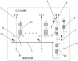
fig. 2 is a schematic diagram illustrating a connection manner of a cable terminal station for achieving fast switching of a cable line according to an embodiment of the present application;
FIG. 3 is a schematic diagram illustrating a cable path with a fault through fast switching of the connection mode of the cable path according to an embodiment of the present application;
fig. 4 is a schematic diagram illustrating a connection manner of a cable terminal station to implement fast switching of a cable line according to a second embodiment of the present application;
description of the drawings: 1-spare switching line; 2-a line of outgoing lines; 3-switching bus; 4-a first arrester; 5-a first voltage transformer; 6-a first switching breaker; 7-a second arrester; 8-a first cable termination; 9-a first high voltage reactor; 10-a second switching breaker; 11-a third arrester; 12-a second voltage transformer; 13-a second cable termination; 14-a second high voltage reactor.
Detailed Description
In order to make the objects, technical solutions and advantages of the embodiments of the present application clearer, the technical solutions in the embodiments of the present application will be clearly and completely described below with reference to the drawings in the embodiments of the present application, and it is obvious that the described embodiments are some embodiments of the present application, but not all embodiments. The components of the embodiments of the present application, generally described and illustrated in the figures herein, can be arranged and designed in a wide variety of different configurations.
Thus, the following detailed description of the embodiments of the present application, presented in the accompanying drawings, is not intended to limit the scope of the claimed application, but is merely representative of selected embodiments of the application. All other embodiments, which can be derived by a person skilled in the art from the embodiments given herein without making any creative effort, shall fall within the protection scope of the present application.
It should be noted that: like reference numbers and letters refer to like items in the following figures, and thus, once an item is defined in one figure, it need not be further defined and explained in subsequent figures.
In the description of the present application, it should be noted that the terms "center", "upper", "lower", "left", "right", "vertical", "horizontal", "inner", "outer", and the like indicate orientations or positional relationships based on the orientations or positional relationships shown in the drawings or orientations or positional relationships that the products of the present invention are conventionally placed in use, and are used only for convenience in describing the present application and simplifying the description, but do not indicate or imply that the devices or elements referred to must have a specific orientation, be constructed and operated in a specific orientation, and thus, should not be construed as limiting the present application. Furthermore, the terms "first," "second," "third," and the like are used solely to distinguish one from another and are not to be construed as indicating or implying relative importance.
Furthermore, the terms "horizontal", "vertical" and the like do not imply that the components are required to be absolutely horizontal or pendant, but rather may be slightly inclined. For example, "horizontal" merely means that the direction is more horizontal than "vertical" and does not mean that the structure must be perfectly horizontal, but may be slightly inclined.
In the description of the present application, it is further noted that, unless expressly stated or limited otherwise, the terms "disposed," "mounted," "connected," and "connected" are to be construed broadly, e.g., as meaning either a fixed connection, a removable connection, or an integral connection; can be mechanically or electrically connected; they may be connected directly or indirectly through intervening media, or they may be interconnected between two elements. The specific meaning of the above terms in the present application can be understood in a specific case by those of ordinary skill in the art.
Fig. 1 shows a schematic diagram of a conventional wiring manner of a cable terminal station according to an embodiment of the present application.
The cable terminal station is a power transmission and transformation facility for realizing the conversion from an overhead line to a cable line, and a conventional cable terminal station is generally only provided with a cable terminal and a lightning arrester, wherein the cable terminal is a core device for realizing the conversion from the overhead line to the cable line. Usually, according to actual requirements of different power grid systems, a part of cable terminal stations need to be additionally provided with high-voltage reactors because station (plant) areas on two sides of a cable line do not have the condition of additionally providing the high-voltage reactors. The conventional wiring mode of the cable terminal station comprises a multi-loop outlet line, wherein each loop outlet line is connected with a lightning arrester arranged close to an overhead line side through a voltage transformer and is arranged at a cable terminal close to a cable line side.
Fig. 2 is a schematic diagram illustrating a connection manner of a cable terminal station to implement fast switching of a cable line according to an embodiment of the present application.
The application provides a pair of cable terminal station realizes cable run fast switch's mode of connection includes: the system comprises a standby switching line 1 arranged in a cable terminal station, a multi-loop outgoing line 2 running in parallel and a transfer bus 3; the standby switching line 1 comprises a first lightning arrester 4 close to the side of the overhead line, the first lightning arrester 4 is connected with a first voltage transformer 5 to form parallel connection, the first voltage transformer 5 is connected with a first switching breaker 6 through an isolating switch, and the first switching breaker 6 is connected with a first cable terminal 8 through a second lightning arrester 7 along the direction perpendicular to the standby switching line 1; the first cable terminal 8 is connected with a first high-voltage reactor 9 through an isolating switch, wherein the first cable terminal 8 is close to the side of a cable line, and the first high-voltage reactor 9 is close to the side of an overhead line; the first switching breaker 6 passes through the side of the disconnector in the direction of the cable side, to which the second switching breaker 10 is connected; each loop of the outgoing line 2 comprises a third lightning arrester 11 close to the overhead line side, the third lightning arrester 11 is connected with a second cable terminal 13 through a second voltage transformer 12 along the direction of the cable line side, and the third lightning arrester 11 is connected with a second high-voltage reactor 14 through an isolation switch along the direction perpendicular to the outgoing line 2; the switching bus 3 transversely passes through the outgoing line 2 along the horizontal direction, and one side of the switching bus 3 close to the standby switching line 1 is connected with the other side of the second switching circuit breaker 10 through a disconnecting switch.
In some embodiments, the second cable termination 13 is disposed near the cable line side. In some embodiments, the first arrester 4, the second arrester 7, and the third arrester 11 are zinc oxide arresters for voltage protection. In some embodiments, the switches within the cable end station are all SF' s6An insulated switch.
The standby switching line 1 is formed by transforming one outgoing line, and the power supply of the cable line with the fault is recovered by switching a part of the cable line with the fault to the standby switching line 1. Normally, the standby switching line 1 is normally operated when no fault occurs, and when other cable lines (i.e., important cable lines) which need to be repaired in time have faults, the standby switching line 1 exits from normal operation, and the cable sections of the standby switching line are switched to be used by the faulty cable lines. The standby switching line 1 arranged along the vertical direction comprises a first lightning arrester 4 arranged close to an overhead line, the first lightning arrester 4 is connected with a first voltage transformer 5, the first voltage transformer 5 is connected with a first switching circuit breaker 6 through an isolating switch, a first cable terminal 8 arranged close to a cable line side is connected along the horizontal direction of the first switching circuit breaker 6 through a second lightning arrester 7, a first high-voltage reactor 9 is connected along one side of the first cable terminal 8 far away from the cable line side (namely, close to the overhead line side) through an isolating switch, and the first high-voltage reactor 9 and the first cable terminal 8 are arranged in the vertical direction; a second switching breaker 10 is connected through a disconnector along a vertical direction of the first switching breaker 6, and the second switching breaker 10 is connected with a transfer bus 3 through the disconnector.
In some embodiments, each outgoing line 2 arranged in the vertical direction includes a third arrester 11 arranged near the overhead line side, a second high voltage reactor 14 is connected through a disconnector in the horizontal direction of the third arrester 11, and a second cable terminal 13 arranged near the cable line side is connected through a second voltage transformer 12 in the vertical direction of the third arrester 11. The lightning arrester plays a role in overvoltage protection for a cable terminal and a cable line, and comprises a first lightning arrester 4, a second lightning arrester 7 and a third lightning arrester 11.
The high-voltage reactor has the functions of compensating the reactive power requirement of a cable line, suppressing overvoltage, performing heavy breakdown and the like.
In some embodiments, the switching bus 3 arranged in the horizontal direction crosses each loop of the outgoing line 2, the switching bus 3 is connected with the second switching breaker 10 through a disconnecting switch, and the first switching breaker 6 and the second switching breaker 10 are controlled by the switch to realize the connection between the standby switching line 1 and the cable line with a fault, so as to further realize the fast switching of the cable line in the cable terminal station, so that when the fault cable line is overhauled, the power failure period is shortened, the time of nearly one month is reduced to about 1 day, and the economic loss caused by the long-term power failure of the important cable line is greatly reduced. When the outlet line is not in fault, the switching bus 3 is not electrically connected with the line. Wherein, the Current Transformer (CT) and the switch which are needed to be installed at the two sides of the breaker.
Fig. 3 is a schematic diagram illustrating a cable line access with a fault through a fast switching connection manner of the cable line according to an embodiment of the present application.
In some embodiments, the fast switching of the cable lines is realized by controlling the switches of the first switching breaker 6 and the second switching breaker 10, and the specific implementation process is as follows:
when the first switching breaker 6 (i.e., the switching breaker disposed on the overhead line side) is closed and the second switching breaker 10 (i.e., the switching breaker disposed on the transfer bus side) is opened, the backup switching line 1 operates in a normal operation manner; if the 1# outgoing line has a fault, firstly, removing connecting wires of a third lightning arrester 11, a second voltage transformer 12 and a second cable terminal 13 to enable a part of the faulty cable line to exit; secondly, the second high-voltage reactor 14 is withdrawn by removing the connecting lead of the second high-voltage reactor 14; thirdly, connecting the conductor in the 1# outgoing line overhead line side station with the switching bus 3, completing the first connection change in the cable terminal station, and predicting a construction period of 1 day; and finally, the standby switching line 1 is in a power failure state, the first switching circuit breaker 6 is opened, the second switching circuit breaker 10 is closed, if a fault loop is inconsistent with the standby switching line, an SD (secure digital) switch for a protection device needs to be operated, the protection devices at two ends of the line are matched, and a second cable needing to be reconnected is laid in advance, so that the part of workload is expected to be in a half day of a construction period. Because the first and second wire changes belong to different working planes and can be implemented simultaneously, the cable line switching work can be completed within 1 day. After the cable line is switched, the switches at the two ends of the 1# outgoing line are closed, the outgoing line 1 can recover the live operation, and the electric loop of the outgoing line is shown by a dash-dot line in fig. 3.
Fig. 4 is a schematic diagram illustrating a connection manner of a cable termination station to implement fast switching of a cable line according to another embodiment of the present application.
The connection mode for realizing the quick switching of the cable line by the cable terminal station is applied to the upper dry village terminal station in the floor engineering of the 330KV overhead transmission line relocation in northeast of Xian. A6-circuit 330kV overhead line transfer cable is built at a terminal station in the dry village, wherein a 90Mvar line high-voltage reactor is configured in 3 circuits, a 75Mvar line high-voltage reactor is configured in 2 circuits, and completed supporting lines comprise an Olympic 1 line, an Olympic 2 line and a Beile 1 line. The Beile 1 line is reformed to form a Jingwei 750-Linxi Gao station-Beijing suburb 330 loop (shown in a dotted line frame in figure 4), a Jingxuan 2 line overhead line is adopted on the side of the overhead line, a Beile 1 line cable line is adopted on the side of the cable line, and a Beile 1 line high-voltage reactor is adopted on the high-voltage reactor. The transfer bus adopts a suspended flexible bus, and the conducting wire adopts NRLH60GJ-1400 heat-resistant steel-cored aluminum stranded wire to meet the requirement of the through-current capacity of each loop. The circuit breaker apparatus employs an HGIS to meet compact building area requirements. According to the actual requirements of engineering, four-end electrical interfaces are arranged, namely an overhead side sleeve, a bus side sleeve, a high-impedance side sleeve and a cable bin, and 400 omega closing resistors are additionally arranged on the two circuit breakers, so that the operation overvoltage is effectively inhibited. The Jingwei 750-Linxi high-resistance station-Beijing 330 loop is already built and successfully put into operation at 25/8 of 2021.
The beneficial effect of this application: the switching bus is additionally arranged to realize the rapid switching transformation of the standby switching line; furthermore, the switching of the cable line of the cable terminal station is realized by controlling the switch of the switching breaker, so that the power failure period caused by the fault of the cable line can be greatly shortened, the residual monthly voltage is reduced to about 1 day, and the economic loss caused by long-term power failure of an important line is greatly reduced; thereby effectively improving the operation stability of the power grid and improving the operation flexibility of the cable terminal station; meanwhile, the dilemma that the cable cannot fall to the ground due to long-time power failure after the important line is difficult to be cabled is avoided, and the cable has positive popularization effects on the use of the ultrahigh-voltage cable and the overhead line falling project.
Additionally, the order in which elements and sequences of the processes described herein are processed, the use of alphanumeric characters, or the use of other designations, is not intended to limit the order of the processes and methods described herein, unless explicitly claimed. While various presently contemplated embodiments of the invention have been discussed in the foregoing disclosure by way of example, it is to be understood that such detail is solely for that purpose and that the appended claims are not limited to the disclosed embodiments, but, on the contrary, are intended to cover all modifications and equivalent arrangements that are within the spirit and scope of the embodiments herein. For example, although the system components described above may be implemented by hardware devices, they may also be implemented by software-only solutions, such as installing the described system on an existing server or mobile device.
Similarly, it should be noted that in the preceding description of embodiments of the application, various features are sometimes grouped together in a single embodiment, figure, or description thereof for the purpose of streamlining the disclosure aiding in the understanding of one or more of the embodiments. This method of disclosure, however, is not intended to require more features than are expressly recited in the claims. Indeed, the embodiments may be characterized as having less than all of the features of a single embodiment disclosed above.
The entire contents of each patent, patent application publication, and other material cited in this application, such as articles, books, specifications, publications, documents, and the like, are hereby incorporated by reference into this application. Except where the application is filed in a manner inconsistent or contrary to the present disclosure, and except where the claim is filed in its broadest scope (whether present or later appended to the application) as well. It is noted that the descriptions, definitions and/or use of terms in this application shall control if they are inconsistent or contrary to the statements and/or uses of the present application in the material attached to this application.
Claims (4)
1. A connection mode for realizing fast switching of cable lines of a cable terminal station is characterized by comprising the following steps: the standby switching circuit, the multi-loop outgoing line and the switching bus are arranged in the cable terminal station;
the standby switching line comprises a first lightning arrester close to the side of the overhead line, the first lightning arrester is connected with a first voltage transformer to form parallel connection, the first voltage transformer is connected with a first switching circuit breaker through an isolating switch, and the first switching circuit breaker is connected with a first cable terminal through a second lightning arrester along the direction perpendicular to the standby switching line; the first cable terminal is connected with a first high-voltage reactor through an isolation switch, wherein the first cable terminal is close to the side of a cable line, and the first high-voltage reactor is close to the side of an overhead line; the first switching breaker is connected with one side of a second switching breaker through an isolation switch along the direction of the cable line side; each loop of the outgoing line comprises a third lightning arrester close to the side of the overhead line, the third lightning arrester is connected with a second cable terminal through a second voltage transformer in the direction of the side of the cable line, and the third lightning arrester is connected with a second high-voltage reactor through an isolation switch in the direction perpendicular to the outgoing line; the switching bus transversely passes through the outgoing line in the horizontal direction, and one side of the switching bus close to the standby switching line is connected with the other side of the second switching circuit breaker through a disconnecting switch.
2. A termination for cable termination according to claim 1, wherein the second cable termination is arranged close to the cable side.
3. The connection mode of cable terminal station for realizing fast switching of cable line according to claim 1, wherein said first lightning arrester, said second lightning arrester and said third lightning arrester are all zinc oxide lightning arresters for realizing voltage protection.
4. The connection method of claim 1, wherein the switches in the cable end station are all SF6An insulated switch.
Priority Applications (1)
| Application Number | Priority Date | Filing Date | Title |
|---|---|---|---|
| CN202210031997.1A CN114362166A (en) | 2022-01-12 | 2022-01-12 | Wiring mode for realizing fast switching of cable lines in cable terminal station |
Applications Claiming Priority (1)
| Application Number | Priority Date | Filing Date | Title |
|---|---|---|---|
| CN202210031997.1A CN114362166A (en) | 2022-01-12 | 2022-01-12 | Wiring mode for realizing fast switching of cable lines in cable terminal station |
Publications (1)
| Publication Number | Publication Date |
|---|---|
| CN114362166A true CN114362166A (en) | 2022-04-15 |
Family
ID=81109553
Family Applications (1)
| Application Number | Title | Priority Date | Filing Date |
|---|---|---|---|
| CN202210031997.1A Pending CN114362166A (en) | 2022-01-12 | 2022-01-12 | Wiring mode for realizing fast switching of cable lines in cable terminal station |
Country Status (1)
| Country | Link |
|---|---|
| CN (1) | CN114362166A (en) |
Cited By (2)
| Publication number | Priority date | Publication date | Assignee | Title |
|---|---|---|---|---|
| CN115148409A (en) * | 2022-08-06 | 2022-10-04 | 安徽徽宁电器仪表集团有限公司 | A control cable that can be temporarily switched in the event of a fault |
| CN121417206A (en) * | 2025-12-26 | 2026-01-27 | 中国电力工程顾问集团华东电力设计院有限公司 | Supports gas-insulated transmission line systems with multiple circuits serving as backups for each other. |
Citations (2)
| Publication number | Priority date | Publication date | Assignee | Title |
|---|---|---|---|---|
| CN113595079A (en) * | 2021-08-27 | 2021-11-02 | 中国能源建设集团陕西省电力设计院有限公司 | High-voltage cable terminal device for power transmission line |
| CN113708280A (en) * | 2021-08-27 | 2021-11-26 | 中国能源建设集团陕西省电力设计院有限公司 | High-voltage cable compensation station wiring mode |
-
2022
- 2022-01-12 CN CN202210031997.1A patent/CN114362166A/en active Pending
Patent Citations (2)
| Publication number | Priority date | Publication date | Assignee | Title |
|---|---|---|---|---|
| CN113595079A (en) * | 2021-08-27 | 2021-11-02 | 中国能源建设集团陕西省电力设计院有限公司 | High-voltage cable terminal device for power transmission line |
| CN113708280A (en) * | 2021-08-27 | 2021-11-26 | 中国能源建设集团陕西省电力设计院有限公司 | High-voltage cable compensation station wiring mode |
Cited By (3)
| Publication number | Priority date | Publication date | Assignee | Title |
|---|---|---|---|---|
| CN115148409A (en) * | 2022-08-06 | 2022-10-04 | 安徽徽宁电器仪表集团有限公司 | A control cable that can be temporarily switched in the event of a fault |
| CN115148409B (en) * | 2022-08-06 | 2025-04-08 | 安徽徽宁电器仪表集团有限公司 | A control cable that can be temporarily switched in case of failure |
| CN121417206A (en) * | 2025-12-26 | 2026-01-27 | 中国电力工程顾问集团华东电力设计院有限公司 | Supports gas-insulated transmission line systems with multiple circuits serving as backups for each other. |
Similar Documents
| Publication | Publication Date | Title |
|---|---|---|
| CN109347134B (en) | Bipolar flexible DC power grid pole line electrical main wiring system and online maintenance method | |
| CN1054005C (en) | Gas insulation switch device and power transmission system by using said switch device | |
| CN110380340B (en) | Substation power distribution device | |
| CN106885959B (en) | Test method for replacing short-circuit copper bar by grounding knife switch in power plant electric main start test | |
| CN107240884B (en) | Distribution device HGIS equipment's arrangement structure | |
| CN210693223U (en) | A voltage transformer isolation combined device applied to non-power-off operation | |
| CN112151297A (en) | A splicing plug-in busbar earthing switch based on busbar post insulators | |
| CN220399541U (en) | DC resistance test system for high-voltage side of transformer | |
| CN213990152U (en) | 330kV High Voltage Shunt Reactor Compensation Station System | |
| CN211018214U (en) | Fixed pure air gap line lightning protection device capable of being replaced in electrified mode | |
| CN109244916B (en) | 750kV distribution device arrangement structure | |
| CN224153781U (en) | Z-shaped gas-insulated metal-enclosed switchgear | |
| JPH0515020A (en) | Gas insulated switchgear | |
| Wu et al. | Research of short circuit Level Improvement of Transformation Substation Equipment | |
| CN219371845U (en) | An open combination electric appliance | |
| CN223363602U (en) | Switch cabinet | |
| CN111864551B (en) | Main wiring structure of transformer substation | |
| CN222381181U (en) | Environment-friendly gas-insulated ring main unit with cable testing function | |
| CN115833377B (en) | A switching system and method for replacing a high-voltage cable sheath protector without power outage | |
| JP3763988B2 (en) | How to update switchgear | |
| CN121643195A (en) | Portable branch box for maintenance and replacement of switchgear in residential areas and methods for short-term power outages. | |
| CN108281917B (en) | An ultra-high voltage AC substation and its design method | |
| CN110165563A (en) | A kind of 220kV HGIS power distribution equipment applied to substation's single-trunk segmental wiring | |
| Lav et al. | Practical design considerations for application of GIS MV switchgear | |
| Yin et al. | Research on Electric Field Distributions of Gas Chambers of Double-Fracture Disconnect Switches for 110kV Gas Insulated Substations In-service Expansions |
Legal Events
| Date | Code | Title | Description |
|---|---|---|---|
| PB01 | Publication | ||
| PB01 | Publication | ||
| SE01 | Entry into force of request for substantive examination | ||
| SE01 | Entry into force of request for substantive examination | ||
| RJ01 | Rejection of invention patent application after publication |
Application publication date: 20220415 |
|
| RJ01 | Rejection of invention patent application after publication |