CN114352828A - Quick connector with locking function - Google Patents

Quick connector with locking function Download PDF

Info

Publication number
CN114352828A
CN114352828A CN202210046392.XA CN202210046392A CN114352828A CN 114352828 A CN114352828 A CN 114352828A CN 202210046392 A CN202210046392 A CN 202210046392A CN 114352828 A CN114352828 A CN 114352828A
Authority
CN
China
Prior art keywords
valve body
connector
female
female joint
male connector
Prior art date
Legal status (The legal status is an assumption and is not a legal conclusion. Google has not performed a legal analysis and makes no representation as to the accuracy of the status listed.)
Pending
Application number
CN202210046392.XA
Other languages
Chinese (zh)
Inventor
高发华
Current Assignee (The listed assignees may be inaccurate. Google has not performed a legal analysis and makes no representation or warranty as to the accuracy of the list.)
Nuotong Suzhou Fluid System Technology Co ltd
Original Assignee
Nuotong Suzhou Fluid System Technology Co ltd
Priority date (The priority date is an assumption and is not a legal conclusion. Google has not performed a legal analysis and makes no representation as to the accuracy of the date listed.)
Filing date
Publication date
Application filed by Nuotong Suzhou Fluid System Technology Co ltd filed Critical Nuotong Suzhou Fluid System Technology Co ltd
Priority to CN202210046392.XA priority Critical patent/CN114352828A/en
Publication of CN114352828A publication Critical patent/CN114352828A/en
Pending legal-status Critical Current

Links

Images

Classifications

    • F—MECHANICAL ENGINEERING; LIGHTING; HEATING; WEAPONS; BLASTING
    • F16—ENGINEERING ELEMENTS AND UNITS; GENERAL MEASURES FOR PRODUCING AND MAINTAINING EFFECTIVE FUNCTIONING OF MACHINES OR INSTALLATIONS; THERMAL INSULATION IN GENERAL
    • F16L—PIPES; JOINTS OR FITTINGS FOR PIPES; SUPPORTS FOR PIPES, CABLES OR PROTECTIVE TUBING; MEANS FOR THERMAL INSULATION IN GENERAL
    • F16L37/00—Couplings of the quick-acting type
    • F16L37/28—Couplings of the quick-acting type with fluid cut-off means
    • F16L37/30—Couplings of the quick-acting type with fluid cut-off means with fluid cut-off means in each of two pipe-end fittings
    • F16L37/32—Couplings of the quick-acting type with fluid cut-off means with fluid cut-off means in each of two pipe-end fittings at least one of two lift valves being opened automatically when the coupling is applied

Landscapes

  • Engineering & Computer Science (AREA)
  • General Engineering & Computer Science (AREA)
  • Mechanical Engineering (AREA)
  • Quick-Acting Or Multi-Walled Pipe Joints (AREA)

Abstract

本发明公开了一种具有锁紧功能的快速接头,包括公接头和母接头,公接头包括公接头阀体、公接头阀芯和公接头弹簧;母接头包括母接头阀体、母接头阀套、母接头阀芯和母接头弹簧;母接头阀体的前端周壁上设有导向斜槽,导向斜槽中设有锁紧针,锁紧针垂直于母接头阀体的轴线,锁紧针的中部位于母接头阀体内,母接头阀体的前端套装有手动圈,手动圈和母接头阀体之间设有顶紧环,顶紧环位于锁紧针的后侧,且顶紧环与手动圈连接,锁紧针的两端分别与顶紧环的端面紧贴;公接头阀体的周壁上设有可与锁紧针配合锁紧的凸环,凸环具有可作用于锁紧针中部的前侧斜面和后侧斜面。本发明一种具有锁紧功能的快速接头,其锁紧稳定性好,且能够单手操作。
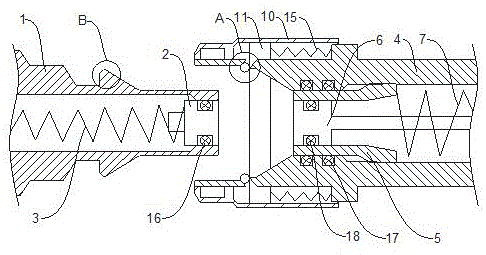
Figure 202210046392

The invention discloses a quick connector with locking function, comprising a male connector and a female connector. The male connector includes a male connector valve body, a male connector valve core and a male connector spring; the female connector includes a female connector valve body and a female connector valve sleeve. , female joint valve core and female joint spring; there is a guide chute on the front end peripheral wall of the female joint valve body, and a locking needle is arranged in the guiding chute, the locking needle is perpendicular to the axis of the female joint valve body, and the The middle part is located in the valve body of the female connector. The front end of the valve body of the female connector is covered with a manual ring. A top tightening ring is arranged between the manual ring and the valve body of the female connector. The two ends of the locking needle are in close contact with the end face of the top locking ring respectively; the peripheral wall of the valve body of the male joint is provided with a convex ring that can be locked with the locking needle. front and rear bevels. The present invention is a quick connector with locking function, which has good locking stability and can be operated with one hand.

Figure 202210046392

Description

Quick connector with locking function
Technical Field
The invention relates to a quick connector with a locking function.
Background
The fluid connector is used as an important component in a liquid cooling system, the main function of the fluid connector is to realize the quick on-off of fluid passages such as pipelines and cold plates, the debugging and the maintenance of equipment are convenient, and especially for the occasions requiring repeated disassembly and assembly and repeated debugging, the quick on-off of the fluid connector has important influence on the debugging and the maintenance efficiency of the assembly. The locking mode of the current commonly used fluid connector comprises a bayonet type and a steel ball locking mode, the operation force is large in the inserting and closing process of the locking mode, the operation hand feeling is not good, the operation can not be carried out by one hand especially under the condition that the operation space is not enough, and the convenience in use is greatly reduced.
Disclosure of Invention
The invention aims to provide a quick connector with a locking function, which has the advantages of reasonable structure and good locking stability, and can be operated by one hand to improve convenience.
In order to achieve the purpose, the technical scheme of the invention is to design a quick connector with a locking function, which comprises a male connector and a female connector, wherein the front ends of the male connector and the female connector are butt ends respectively, and the male connector comprises a male connector valve body, a male connector valve core and a male connector spring; the female joint comprises a female joint valve body, a female joint valve sleeve, a female joint valve core and a female joint spring; the front end peripheral wall of the female joint valve body is provided with a guide chute penetrating through the peripheral wall of the female joint valve body along the wall thickness direction of the female joint valve body, a locking needle is arranged in the guide chute and is perpendicular to the axis of the female joint valve body, the middle part of the locking needle is positioned in the female joint valve body and can move close to or far away from the axis of the female joint valve body along the guide chute, the front end of the female joint valve body is sleeved with a manual ring, a puller ring is arranged between the manual ring and the female joint valve body and is positioned at the rear side of the locking needle, the puller ring is connected with the manual ring, and two ends of the locking needle are respectively clung to the end face of the puller ring; and a convex ring which can be matched and locked with the locking needle is arranged on the peripheral wall of the male connector valve body, and the convex ring is provided with a front side inclined plane and a rear side inclined plane which can act on the middle part of the locking needle. Through adopting above-mentioned scheme, when carrying out the connection operation of male joint and female joint, the one hand inserts the male joint valve body in the female joint valve body, bulge loop on the male joint valve body will promote the locking needle through the front side inclined plane and move backward and keep away from the axis of female joint valve body along the direction chute, this in-process locking needle will drive top tight ring and manual circle and retreat and compress compression spring, when the bulge loop moves to crossing the locking needle, top tight ring will promote the locking needle to reset under compression spring's elasticity effect, make the locking needle card in the rear side of bulge loop, and locking needle and rear side inclined plane contact, male joint valve body can't return this moment, accomplish male joint and female joint's being connected. When the disconnection operation of the male connector and the female connector is carried out, the manual ring is pulled by one hand to retreat, the manual ring drives the jacking ring to retreat so as to release jacking of the locking needle, at the moment, the female connector spring applies acting force to the male connector valve body through the female connector valve sleeve, the convex ring of the male connector valve body pushes the locking needle backwards through the rear side inclined plane until the locking needle moves to the edge of the rear side inclined plane, at the moment, the male connector valve body retreats from the female connector valve body under the elastic force action of the female connector spring, and disconnection of the male connector and the female connector is completed.
Preferably, the number of the guide chutes arranged on the peripheral wall of the front end of the female joint valve body is two, the two guide chutes are symmetrically arranged along the axis of the female joint valve body, and the locking needle is arranged in each guide chute.
Preferably, a compression spring is connected to the rear side of the jacking ring.
Preferably, the male joint valve core is movably arranged in the male joint valve body, and the male joint spring is connected with the male joint valve core; the female joint valve core is fixedly arranged in the female joint valve body, the female joint valve sleeve is movably arranged in the female joint valve body, the female joint valve sleeve is sleeved on the female joint valve core, and the female joint spring is connected with the female joint valve sleeve.
Preferably, a first sealing ring is arranged between the male connector valve body and the male connector valve core, a second sealing ring is arranged between the female connector valve body and the female connector valve sleeve, and a third sealing ring is arranged between the female connector valve sleeve and the female connector valve core.
Preferably, a first annular groove is formed in the peripheral wall of the male connector valve element, and the first sealing ring is arranged in the first annular groove.
Preferably, a second annular groove is formed in the inner wall of the female joint valve body, and the second sealing ring is arranged in the second annular groove.
Preferably, a third annular groove is formed in the peripheral wall of the female joint valve element, and the third sealing ring is arranged in the third annular groove.
The invention has the advantages and beneficial effects that: the utility model provides a quick-operation joint with locking function, its is rational in infrastructure, has the good advantage of locking stability, and can one-hand operation to improve the convenience.
In addition, the first sealing ring is arranged between the male connector valve body and the male connector valve core, so that the male connector can be effectively prevented from being polluted by the outside in the unused state; the second sealing ring is arranged between the female joint valve body and the female joint valve sleeve, and the third sealing ring is arranged between the female joint valve sleeve and the female joint valve core, so that the female joint can be effectively prevented from being polluted by the outside in an unused state.
Drawings
FIG. 1 is a schematic of the present invention.
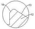
Fig. 2 is an enlarged view at a in fig. 1.
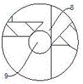
Fig. 3 is an enlarged view at B in fig. 1.
Detailed Description
The following description of the embodiments of the present invention will be made with reference to the accompanying drawings. The following examples are only for illustrating the technical solutions of the present invention more clearly, and the protection scope of the present invention is not limited thereby.
The technical scheme of the specific implementation of the invention is as follows:
as shown in fig. 1, 2 and 3, a quick connector with a locking function includes a male connector and a female connector, each of which has a front end as a butt end, the male connector including a male connector valve body 1, a male connector valve core 2 and a male connector spring 3; the female joint comprises a female joint valve body 4, a female joint valve sleeve 5, a female joint valve core 6 and a female joint spring 7; a guide chute 8 penetrating through the peripheral wall of the female joint valve body 4 along the wall thickness direction of the female joint valve body 4 is arranged on the peripheral wall of the front end of the female joint valve body 4, a locking needle 9 is arranged in the guide chute 8, the locking needle 9 is perpendicular to the axis of the female joint valve body 4, the middle part of the locking needle 9 is positioned in the female joint valve body 4, the locking needle 9 can move along the axis of the guide chute 8 close to or far away from the female joint valve body 4, a manual ring 10 is sleeved at the front end of the female joint valve body 4, a puller ring 11 is arranged between the manual ring 10 and the female joint valve body 4, the puller ring 11 is positioned at the rear side of the locking needle 9, the puller ring 11 is connected with the manual ring 10, and two ends of the locking needle 9 are respectively attached to the end surface of the puller ring 11; the peripheral wall of the male connector valve body 1 is provided with a convex ring 12 which can be matched and locked with the locking needle 9, and the convex ring 12 is provided with a front side inclined surface 13 and a rear side inclined surface 14 which can act on the middle part of the locking needle 9.
The number of the guide chutes 8 provided on the peripheral wall of the front end of the female joint valve body 4 is two, the two guide chutes 8 are symmetrically arranged with respect to the axis of the female joint valve body 4, and the locking pin 9 is provided in each guide chute 8.
A compression spring 15 is connected to the rear side of the tightening ring 11.
The male joint valve core 2 is movably arranged in the male joint valve body 1, and the male joint spring 3 is connected with the male joint valve core 2; the female joint valve core 6 is fixedly arranged in the female joint valve body 4, the female joint valve sleeve 5 is movably arranged in the female joint valve body 4, the female joint valve sleeve 5 is sleeved on the female joint valve core 6, and the female joint spring 7 is connected with the female joint valve sleeve 5.
A first sealing ring 16 is arranged between the male connector valve body 1 and the male connector valve core 2, a second sealing ring 17 is arranged between the female connector valve body 4 and the female connector valve sleeve 5, and a third sealing ring 18 is arranged between the female connector valve sleeve 5 and the female connector valve core 6.
The peripheral wall of the male connector valve element 2 is provided with a first annular groove, and the first seal ring 16 is disposed in the first annular groove.
A second annular groove is formed in the inner wall of the female joint valve body 4, and the second seal ring 17 is disposed in the second annular groove.
A third annular groove is provided in the peripheral wall of the female joint valve element 6, and the third seal ring 18 is provided in the third annular groove.
The invention relates to a using method of a quick joint with a locking function, which comprises the following steps: when the connection operation of the male connector and the female connector is carried out, the male connector valve body 1 is inserted into the female connector valve body 4 by one hand, the male connector valve body 1 is firstly contacted with the female connector valve sleeve 5 and is pressed into the female connector valve body 4 together against the female connector valve sleeve 5, the female connector spring 7 is compressed, meanwhile, the female connector valve core 6 is pressed into the male connector valve body 1 against the male connector valve core 2, and the male connector spring 3 is compressed. Along with the increase of the pressing force, the mutual pressing depth of the male end and the female end is deepened, the convex ring 12 on the male connector valve body 1 pushes the locking needle 9 to move backwards along the guide inclined groove 8 through the front side inclined surface 13 and to be away from the axis of the female connector valve body 4, the locking needle 9 in the process drives the jacking ring 11 and the manual ring 10 to retreat and compress the compression spring 15, until the convex ring 12 moves to cross over the locking needle 9, the jacking ring 11 pushes the locking needle 9 to reset under the elastic force of the compression spring 15, so that the locking needle 9 is clamped on the rear side of the convex ring 12, the locking needle 9 is in contact with the rear side inclined surface 14 of the convex ring 12, at the moment, the male connector valve body 1 cannot retreat, and the flow passage in the male connector valve body 1 is communicated with the flow passage in the female connector valve body 4, and the connection operation of the male connector and the female connector is completed. When the disconnection operation of the male connector and the female connector is carried out, the manual ring 10 is pulled by a single hand to retreat, the manual ring 10 drives the jacking ring 11 to retreat so as to release the jacking of the locking needle 9, at the moment, the female connector spring 7 applies acting force to the male connector valve body 1 through the female connector valve sleeve 5, the convex ring 12 of the male connector valve body 1 pushes the locking needle 9 backwards through the rear side inclined plane 14 until the locking needle 9 moves to the edge of the rear side inclined plane 14, at the moment, the male connector valve body 1 withdraws from the female connector valve body 4 under the elastic force action of the female connector spring 7, and therefore the disconnection operation of the male connector and the female connector is completed.
The foregoing is only a preferred embodiment of the present invention, and it should be noted that, for those skilled in the art, various modifications and decorations can be made without departing from the technical principle of the present invention, and these modifications and decorations should also be regarded as the protection scope of the present invention.

Claims (8)

1. A quick connector with a locking function comprises a male connector and a female connector, wherein the front ends of the male connector and the female connector are butt ends respectively, and the male connector comprises a male connector valve body, a male connector valve core and a male connector spring; the female joint comprises a female joint valve body, a female joint valve sleeve, a female joint valve core and a female joint spring and is characterized in that a guide chute penetrating through the peripheral wall of the female joint valve body along the wall thickness direction of the female joint valve body is arranged on the peripheral wall of the front end of the female joint valve body, a locking needle is arranged in the guide chute and perpendicular to the axis of the female joint valve body, the middle of the locking needle is positioned in the female joint valve body and can move close to or far away from the axis of the female joint valve body along the guide chute, a manual ring is sleeved at the front end of the female joint valve body, a jacking ring is arranged between the manual ring and the female joint valve body and positioned at the rear side of the locking needle and connected with the manual ring, and two ends of the locking needle are respectively clung to the end faces of the jacking ring; and a convex ring which can be matched and locked with the locking needle is arranged on the peripheral wall of the male connector valve body, and the convex ring is provided with a front side inclined plane and a rear side inclined plane which can act on the middle part of the locking needle.
2. The quick connector with locking function according to claim 1, wherein the number of the guide diagonal grooves provided on the front end peripheral wall of the female connector valve body is two, the two guide diagonal grooves being provided symmetrically with respect to the axis of the female connector valve body, the locking pin being provided in each of the guide diagonal grooves.
3. The quick connector with locking function according to claim 1, wherein a compression spring is connected to a rear side of the tightening ring.
4. The quick connector with locking function according to claim 1, wherein the male connector valve core is movably arranged in the male connector valve body, and the male connector spring is connected with the male connector valve core; the female joint valve core is fixedly arranged in the female joint valve body, the female joint valve sleeve is movably arranged in the female joint valve body, the female joint valve sleeve is sleeved on the female joint valve core, and the female joint spring is connected with the female joint valve sleeve.
5. The quick connector with locking function as claimed in claim 1, wherein a first sealing ring is provided between the male connector valve body and the male connector valve core, a second sealing ring is provided between the female connector valve body and the female connector valve sleeve, and a third sealing ring is provided between the female connector valve sleeve and the female connector valve core.
6. The quick connector with a locking function according to claim 5, wherein a first annular groove is provided on a peripheral wall of the male connector spool, and the first seal ring is provided in the first annular groove.
7. The quick connector with locking function according to claim 5, wherein a second annular groove is provided on the inner wall of the female connector valve body, and the second sealing ring is disposed in the second annular groove.
8. The quick connector with a locking function according to claim 5, wherein a third annular groove is provided on a peripheral wall of the female connector spool, and the third seal ring is provided in the third annular groove.
CN202210046392.XA 2022-01-17 2022-01-17 Quick connector with locking function Pending CN114352828A (en)

Priority Applications (1)

Application Number Priority Date Filing Date Title
CN202210046392.XA CN114352828A (en) 2022-01-17 2022-01-17 Quick connector with locking function

Applications Claiming Priority (1)

Application Number Priority Date Filing Date Title
CN202210046392.XA CN114352828A (en) 2022-01-17 2022-01-17 Quick connector with locking function

Publications (1)

Publication Number Publication Date
CN114352828A true CN114352828A (en) 2022-04-15

Family

ID=81090457

Family Applications (1)

Application Number Title Priority Date Filing Date
CN202210046392.XA Pending CN114352828A (en) 2022-01-17 2022-01-17 Quick connector with locking function

Country Status (1)

Country Link
CN (1) CN114352828A (en)

Cited By (2)

* Cited by examiner, † Cited by third party
Publication number Priority date Publication date Assignee Title
CN116722396A (en) * 2023-08-10 2023-09-08 常州协创智联电子有限公司 Connector wiring fixing device and wiring method
CN118088823A (en) * 2024-02-20 2024-05-28 诺通(苏州)流体系统科技有限公司 A six-way floating mechanism

Citations (3)

* Cited by examiner, † Cited by third party
Publication number Priority date Publication date Assignee Title
CN205118535U (en) * 2015-11-10 2016-03-30 浙江益华制冷设备有限公司 Drainage connector
CN108194738A (en) * 2018-03-05 2018-06-22 浙江艾默樱网络科技有限公司 A kind of double self-locking plug quick couplings
US20200363000A1 (en) * 2019-05-14 2020-11-19 Staubli Faverges Female element and fluid connection

Patent Citations (3)

* Cited by examiner, † Cited by third party
Publication number Priority date Publication date Assignee Title
CN205118535U (en) * 2015-11-10 2016-03-30 浙江益华制冷设备有限公司 Drainage connector
CN108194738A (en) * 2018-03-05 2018-06-22 浙江艾默樱网络科技有限公司 A kind of double self-locking plug quick couplings
US20200363000A1 (en) * 2019-05-14 2020-11-19 Staubli Faverges Female element and fluid connection

Cited By (3)

* Cited by examiner, † Cited by third party
Publication number Priority date Publication date Assignee Title
CN116722396A (en) * 2023-08-10 2023-09-08 常州协创智联电子有限公司 Connector wiring fixing device and wiring method
CN116722396B (en) * 2023-08-10 2023-11-10 常州协创智联电子有限公司 Connector wiring fixing device and wiring method
CN118088823A (en) * 2024-02-20 2024-05-28 诺通(苏州)流体系统科技有限公司 A six-way floating mechanism

Similar Documents

Publication Publication Date Title
CN204829061U (en) High -speed joint connects
CN104132173B (en) Joint structure of American and French dual-purpose air nozzle
CN205118534U (en) U type bayonet lock formula quick -operation joint on stone oil pipe way
CN209818995U (en) Plunger type quick coupling
CN111734908A (en) Quick-insertion connecting structure
ZA200701219B (en) Coupling assembly
CN201170406Y (en) Two-way stagnant water quick detach connects
CN216692618U (en) Quick-operation joint locking mechanism
CN110220052A (en) Plug, socket and connector
CN209399000U (en) A kind of self-locking Water pipe fast-connection head of steel ball
CN218972093U (en) Jaw type sealing connector
CN218863548U (en) A non-detachable quick-plug connector
CN206280640U (en) A kind of snap joint public plug
CN111365544A (en) Hydraulic transition joint of engineering machinery
CN207674011U (en) A kind of adapter assembly for determining core connector and core connector is determined using this
CN210318977U (en) High-sealing-performance quick plug connector
CN222163995U (en) Quick Connectors
CN221800947U (en) A stainless steel hose crimping joint for filtration
CN203880291U (en) Quick-opening-closing flange bronze soft pipe valve with automatic-sealing function of quick pipe connector
CN216112696U (en) A convenient quick connector
CN119914768A (en) Quick Connectors
CN223294465U (en) A non-overflow hydraulic quick connector
CN222702819U (en) Tap joint
CN223215964U (en) Novel liquid cooling quick-operation joint
CN221824770U (en) Stainless steel emulsifying tank pipeline connection structure

Legal Events

Date Code Title Description
PB01 Publication
PB01 Publication
SE01 Entry into force of request for substantive examination
TA01 Transfer of patent application right

Effective date of registration: 20220606

Address after: 200000 No. 722, Mingxing village, Jinhui Town, Fengxian District, Shanghai

Applicant after: Gao Fahua

Address before: 215000 building 3, No. 50, beiguandu Road, Yuexi street, Wuzhong District, Suzhou City, Jiangsu Province

Applicant before: Nuotong (Suzhou) fluid system technology Co.,Ltd.

TA01 Transfer of patent application right

Effective date of registration: 20231023

Address after: No. 50, beiguandu Road, Wuzhong District, Suzhou, Jiangsu 215000

Applicant after: Nuotong (Suzhou) fluid system technology Co.,Ltd.

Address before: 200000 No. 722, Mingxing village, Jinhui Town, Fengxian District, Shanghai

Applicant before: Gao Fahua

RJ01 Rejection of invention patent application after publication

Application publication date: 20220415