CN114347185A - Synchronous cutting and end surface polishing device for building materials and using method thereof - Google Patents
Synchronous cutting and end surface polishing device for building materials and using method thereof Download PDFInfo
- Publication number
- CN114347185A CN114347185A CN202111644673.7A CN202111644673A CN114347185A CN 114347185 A CN114347185 A CN 114347185A CN 202111644673 A CN202111644673 A CN 202111644673A CN 114347185 A CN114347185 A CN 114347185A
- Authority
- CN
- China
- Prior art keywords
- cutting
- plate
- die holder
- cutting die
- rotating shaft
- Prior art date
- Legal status (The legal status is an assumption and is not a legal conclusion. Google has not performed a legal analysis and makes no representation as to the accuracy of the status listed.)
- Withdrawn
Links
- 238000005520 cutting process Methods 0.000 title claims abstract description 241
- 238000005498 polishing Methods 0.000 title claims abstract description 69
- 239000004566 building material Substances 0.000 title claims abstract description 27
- 238000000034 method Methods 0.000 title claims abstract description 15
- 230000001360 synchronised effect Effects 0.000 title claims description 28
- 230000007246 mechanism Effects 0.000 claims abstract description 60
- 230000033001 locomotion Effects 0.000 claims abstract description 14
- 230000009471 action Effects 0.000 claims description 17
- 238000003825 pressing Methods 0.000 claims description 11
- 230000005540 biological transmission Effects 0.000 claims description 10
- 238000009434 installation Methods 0.000 claims description 10
- 230000006835 compression Effects 0.000 claims description 7
- 238000007906 compression Methods 0.000 claims description 7
- 230000000670 limiting effect Effects 0.000 claims description 4
- 230000000149 penetrating effect Effects 0.000 claims description 3
- 238000005056 compaction Methods 0.000 claims description 2
- 239000000919 ceramic Substances 0.000 abstract description 5
- 239000000463 material Substances 0.000 description 10
- 238000000576 coating method Methods 0.000 description 2
- 239000011521 glass Substances 0.000 description 2
- 238000012986 modification Methods 0.000 description 2
- 230000004048 modification Effects 0.000 description 2
- 230000008569 process Effects 0.000 description 2
- 235000017166 Bambusa arundinacea Nutrition 0.000 description 1
- 235000017491 Bambusa tulda Nutrition 0.000 description 1
- 241001330002 Bambuseae Species 0.000 description 1
- 235000015334 Phyllostachys viridis Nutrition 0.000 description 1
- 230000004075 alteration Effects 0.000 description 1
- 239000011425 bamboo Substances 0.000 description 1
- 230000009286 beneficial effect Effects 0.000 description 1
- 239000011449 brick Substances 0.000 description 1
- 239000004568 cement Substances 0.000 description 1
- 239000004567 concrete Substances 0.000 description 1
- 238000010276 construction Methods 0.000 description 1
- 238000005260 corrosion Methods 0.000 description 1
- 230000007797 corrosion Effects 0.000 description 1
- 238000010586 diagram Methods 0.000 description 1
- 230000000694 effects Effects 0.000 description 1
- 229920006351 engineering plastic Polymers 0.000 description 1
- 238000004079 fireproofing Methods 0.000 description 1
- 238000009413 insulation Methods 0.000 description 1
- 239000002184 metal Substances 0.000 description 1
- 239000003973 paint Substances 0.000 description 1
- 238000004321 preservation Methods 0.000 description 1
- 238000007789 sealing Methods 0.000 description 1
- 239000004575 stone Substances 0.000 description 1
- 238000006467 substitution reaction Methods 0.000 description 1
- 238000004078 waterproofing Methods 0.000 description 1
Images





Classifications
-
- B—PERFORMING OPERATIONS; TRANSPORTING
- B27—WORKING OR PRESERVING WOOD OR SIMILAR MATERIAL; NAILING OR STAPLING MACHINES IN GENERAL
- B27C—PLANING, DRILLING, MILLING, TURNING OR UNIVERSAL MACHINES FOR WOOD OR SIMILAR MATERIAL
- B27C5/00—Machines designed for producing special profiles or shaped work, e.g. by rotary cutters; Equipment therefor
- B27C5/02—Machines with table
-
- B—PERFORMING OPERATIONS; TRANSPORTING
- B24—GRINDING; POLISHING
- B24B—MACHINES, DEVICES, OR PROCESSES FOR GRINDING OR POLISHING; DRESSING OR CONDITIONING OF ABRADING SURFACES; FEEDING OF GRINDING, POLISHING, OR LAPPING AGENTS
- B24B21/00—Machines or devices using grinding or polishing belts; Accessories therefor
- B24B21/002—Machines or devices using grinding or polishing belts; Accessories therefor for grinding edges or bevels
-
- B—PERFORMING OPERATIONS; TRANSPORTING
- B24—GRINDING; POLISHING
- B24B—MACHINES, DEVICES, OR PROCESSES FOR GRINDING OR POLISHING; DRESSING OR CONDITIONING OF ABRADING SURFACES; FEEDING OF GRINDING, POLISHING, OR LAPPING AGENTS
- B24B21/00—Machines or devices using grinding or polishing belts; Accessories therefor
- B24B21/18—Accessories
-
- B—PERFORMING OPERATIONS; TRANSPORTING
- B28—WORKING CEMENT, CLAY, OR STONE
- B28D—WORKING STONE OR STONE-LIKE MATERIALS
- B28D1/00—Working stone or stone-like materials, e.g. brick, concrete or glass, not provided for elsewhere; Machines, devices, tools therefor
- B28D1/22—Working stone or stone-like materials, e.g. brick, concrete or glass, not provided for elsewhere; Machines, devices, tools therefor by cutting, e.g. incising
- B28D1/24—Working stone or stone-like materials, e.g. brick, concrete or glass, not provided for elsewhere; Machines, devices, tools therefor by cutting, e.g. incising with cutting discs
Landscapes
- Engineering & Computer Science (AREA)
- Mechanical Engineering (AREA)
- Life Sciences & Earth Sciences (AREA)
- Mining & Mineral Resources (AREA)
- Wood Science & Technology (AREA)
- Forests & Forestry (AREA)
- Finish Polishing, Edge Sharpening, And Grinding By Specific Grinding Devices (AREA)
Abstract
The invention discloses a device for synchronously cutting building materials and polishing end faces and a using method thereof, belonging to the technical field of building material processing, and comprising a U-shaped frame, a cylinder arranged on the frame and a bearing plate arranged at the output end of the cylinder, wherein guide rods III are arranged at four corners of the bearing plate in a sliding manner, the guide rods III are arranged on the frame, and springs II with two ends respectively connected with the bearing plate and the frame are sleeved outside the guide rods III; the cutting mechanism is arranged on the bearing plate in a sliding mode and used for cutting the plate, the cutting compactor consists of a lower supporting assembly and an upper supporting assembly which are arranged oppositely, and the lower supporting assembly consists of a lower cutting die holder and two lower cutting supporting seats on two sides of the lower cutting die holder; connect cutting mechanism and polishing mechanism through link gear for can drive cutting mechanism and polishing mechanism simultaneous movement when the cylinder starts to drive the loading board up-and-down motion, realize carrying out the operation in step to the cutting polishing of ceramic tile panel, promote work efficiency.
Description
Technical Field
The invention belongs to the technical field of building material processing, and particularly relates to a device for synchronously cutting and polishing end faces of building materials and a using method thereof.
Background
Building materials are a general term for materials used in civil engineering and construction. Can be divided into structural materials, decorative materials and some special materials, the structural materials comprise: timber, bamboo timber, stone material, cement, concrete, metal, brick and tile, pottery, glass, engineering plastics, combined material etc. ornamental material includes: various coatings, paints, coatings, veneers, various ceramic tiles, glass with special effects and the like, wherein the special materials are as follows: the material is used for water proofing, moisture proofing, corrosion resistance, fire proofing, flame retardance, sound insulation, heat preservation, sealing and the like.
Add man-hour to the building materials ceramic tile, need cut and tip polishing operation when laying, but current equipment is adding the cutting polishing that lacks the ceramic tile panel and go on in step man-hour, and work efficiency is comparatively low, and can not be fine carry out effective spacing to ceramic tile panel and compress tightly in the processing operation in-process, and then can bring certain influence for cutting and polishing operation, and the function is imperfect.
Disclosure of Invention
The invention aims to provide a synchronous cutting and end face polishing device for building materials and a using method thereof, aiming at solving the problems that the prior equipment needs to perform cutting and end part polishing operations when the building material floor tile is processed, but the prior equipment does not perform cutting and polishing on the floor tile board synchronously when processing, has low working efficiency, can not perform effective limiting and pressing on the floor tile board well in the processing operation process, further brings certain influence on the cutting and polishing operations, and has incomplete functions.
In order to achieve the purpose, the invention provides the following technical scheme: a synchronous cutting and end face polishing device for building materials comprises a U-shaped frame, an air cylinder installed on the frame and a bearing plate installed at the output end of the air cylinder, wherein guide rods III are installed at four corners of the bearing plate in a sliding mode, the guide rods III are installed on the frame, and springs II with two ends respectively connected with the bearing plate and the frame are sleeved outside the guide rods III;
the cutting mechanism is arranged on the bearing plate in a sliding mode and used for cutting the plate;
the cutting presser consists of a lower supporting component and an upper supporting component which are arranged oppositely, wherein the lower supporting component consists of a lower cutting die holder and two lower cutting supporting seats at two sides of the lower cutting die holder, the two lower cutting supporting seats are both arranged on the rack, and the lower cutting die holder is slidably arranged on the outer surface of a sliding rod arranged in the rack;
the telescopic connecting unit is arranged among the lower cutting die holder, the upper cutting die holder and the cutting mechanism and is used for realizing the synchronous motion of the lower cutting die holder, the upper cutting die holder and the cutting mechanism and simultaneously realizing the relative motion of the lower cutting die holder and the upper cutting die holder;
the pressing adjusting mechanism is arranged on the rack and used for realizing synchronous up-and-down movement of the upper supporting assembly when the bearing plate is driven by the cylinder to move up and down so as to realize that the upper supporting assembly and the lower supporting assembly are close to each other when the bearing plate moves up and the upper supporting assembly and the lower supporting assembly are far away from each other when the bearing plate moves down;
the two polishing mechanisms are respectively arranged on the left side and the right side of the rack and are used for polishing two ends of the plate;
and the linkage mechanism is arranged on the rear side of the bearing plate and used for driving the linkage mechanism to synchronously work when the cutting mechanism works so as to realize synchronous cutting and polishing.
By adopting the scheme, the linkage mechanism is arranged to connect the cutting mechanism and the polishing mechanism, so that the cutting mechanism and the polishing mechanism can be driven to synchronously move when the cylinder is started to drive the bearing plate to move up and down, the cutting and polishing of the floor tile panel can be synchronously carried out, the working efficiency is effectively improved, the lower cutting die holder and the upper cutting die holder are arranged to be matched for use, the upper cutting support seat and the lower cutting support seat are matched for use, the upper cutting die holder and the upper cutting support seat are downwards moved when the bearing plate moves up by utilizing the power connection unit, the floor tile panel can be effectively limited and pressed while being cut, the floor tile panel can not be displaced during the cutting and polishing operation, the operation precision is effectively ensured, the locking rod is matched with the first spring for use, and the locking column is clamped into the locking grooves at different positions, and the first telescopic rod and the second telescopic rod are matched to realize that the cutting wheel, the lower cutting die holder and the upper cutting die holder are always in the same vertical plane, so that the lower cutting die holder and the upper cutting die holder can always compress and limit two sides of a cutting part during cutting, the cutting precision is further guaranteed, and the functional diversity is improved.
In the above scheme, it should be noted that the cylinder and the motor are both electrically connected to an external power supply.
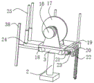
As a preferred embodiment, the cutting mechanism comprises a base arranged on the upper surface of the bearing plate, a first rotating shaft rotatably mounted on the base, a motor which is mounted on the side surface of the base and fixedly connected with one end of the first rotating shaft, a cutting wheel mounted on the outer surface of the first rotating shaft, two trapezoidal blocks mounted on the front side and the rear side of the lower surface of the base, and an L-shaped plate mounted on the front side of the bearing plate, wherein a trapezoidal sliding groove for the trapezoidal blocks to slide is formed in the front side of the bearing plate.
As a preferred embodiment, a locking rod is slidably mounted on the L-shaped plate, a locking column and a locking pulling plate are respectively fixed at two ends of the locking rod, a first spring with two ends respectively connected with the locking column and the L-shaped plate is sleeved on the outer surface of the locking rod, and a plurality of locking grooves for the locking column to insert are formed in the front surface of the bearing plate.
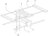
As a preferred embodiment, the telescopic connection unit comprises a supporting block installed on the rear side surface of the base, a first telescopic rod installed on the upper surface of the supporting block and having a top end connected with the lower cutting die holder, and a second telescopic rod installed on the upper surface of the lower cutting die holder and having a top end connected with the upper cutting die holder.
As a preferred embodiment, the pressing adjustment mechanism includes an installation shell installed on the frame, a screw rod with two ends fixed with a second rotating shaft and rotatably installed on the inner wall of the installation shell through the second rotating shaft, a sliding plate installed on the outer surface of the screw rod in a threaded manner, a connecting rod installed on the front surface of the sliding plate and penetrating through a channel formed in the front surface of the installation shell and extending out of the installation shell, and an installation plate installed at the end of the connecting rod, wherein the upper cutting die holder and the upper cutting support holder are both installed on the side surface of the installation plate, a first guide rod is vertically installed in the installation shell, the sliding plate is slidably installed on the outer surface of the first guide rod, and a power connection unit is arranged between the installation shell and the support block.
As a preferred embodiment, the power connection unit comprises a rack plate arranged on the back of the bearing plate, a first fixed seat arranged on the lower surface of the mounting shell, a third rotating shaft rotatably arranged on the first fixed seat, two first bevel gears arranged at one end of the third rotating shaft and at the two ends of one of the rotating shafts and meshed with each other for use, and a cylindrical gear arranged at the other end of the third rotating shaft and meshed with the rack plate for use.
As a preferred embodiment, the polishing mechanism comprises a U-shaped seat which slides up and down on the side surface of the rack and is connected with the bearing plate through a mounting rod, two rotating shafts four which are rotatably installed in the U-shaped seat, two driving rollers which are installed on the outer surfaces of the two rotating shafts four, two driving rollers which are in transmission connection through a polishing belt, a second fixing seat which is installed on the side surface of the U-shaped seat, a fifth rotating shaft which is rotatably installed on the second fixing seat, and two bevel gears two which are installed at one end of the fifth rotating shaft and one end of one of the four rotating shafts four and are used in mutual engagement.
As a preferred embodiment, the link gear includes and installs the fixed disk in the loading board side through the dead lever, rotates the pivot six of installing on the fixed disk, installs the curb plate at the loading board upper surface, rotates the urceolus of installing on the curb plate, the tip of pivot one extends to the urceolus inside and installs the linkage piece, the urceolus inner wall is seted up and is supplied the gliding linkage groove of linkage piece, installs two belt pulleys one that just transmit the connection through the belt at urceolus tip and six surfaces of pivot, installs two belt pulleys two that transmit the connection at five tip of pivot and six tip of pivot and through the belt.
In a preferred embodiment, a second guide rod is mounted on the lower surface of the U-shaped seat, a positioning plate is mounted on the side surface of the frame, and the second guide rod penetrates through the positioning plate in a sliding manner and extends to the lower side of the positioning plate.
A method for using a device for synchronously cutting and polishing end faces of building materials comprises the following steps:
s1, placing the plate to be cut on the lower cutting die holder and the lower cutting support seat and adjusting the position of the plate, the cutting mechanism is adjusted according to the cutting requirement, the locking pulling plate is pulled forwards to drive the locking rod to move during adjustment, the locking rod drives the locking column to be separated from the locking groove and stretches the first spring to contract, the base is held up to drive the cutting wheel to move left and right, the cutting wheel moves until the cutting wheel is positioned under the cutting part, the locking pulling plate is loosened to drive the locking rod to drive the locking column to be clamped into the locking groove at the position at the moment by utilizing the elasticity of the first spring, meanwhile, the base can drive the lower cutting die holder to move synchronously through the telescopic rod when moving, the upper cutting die holder is driven to move synchronously through the telescopic rod II when moving, the base can drive the first rotating shaft to slide in the outer barrel when moving, and the outer barrel can synchronously slide when the first rotating shaft rotates under the limiting action of the linkage block;
s2, starting a cylinder, wherein a cylinder piston rod extends to drive a bearing plate to move upwards, the bearing plate drives a rack plate to move upwards through a supporting block when moving upwards, further drives a cylindrical gear to rotate under the meshing action of the rack plate and the cylindrical gear, further drives a rotating shaft three to rotate, drives a rotating shaft two to drive under the meshing action of two bevel gears I, further drives a screw to rotate, further drives a sliding plate to move downwards, the sliding plate drives a mounting plate to move downwards through a connecting rod, further drives an upper cutting die holder and an upper cutting support holder to move downwards, the upper cutting die holder and a lower cutting die holder are used for realizing the compression of two sides of a cutting part, the upper cutting support holder and the lower cutting support holder are used for realizing the compression of two sides of a plate, meanwhile, a U-shaped holder is driven to move upwards synchronously through the mounting rod when the bearing plate moves upwards, and a motor is started when the cylinder extends, the motor drives the first rotating shaft to rotate, the first rotating shaft drives the cutting wheel to rotate, the first rotating shaft is enabled to rotate six under the action of the first belt pulley and the first belt, the fifth rotating shaft is enabled to rotate under the action of the second belt pulley and the second belt, the fourth rotating shaft is enabled to rotate under the meshing action of the two bevel gears, the polishing belt is driven to rotate through the driving roller, and then cutting and polishing are synchronously conducted under the condition that compaction is achieved.
Compared with the prior art, the invention has the beneficial effects that:
according to the synchronous cutting and end face polishing device for the building materials and the using method thereof, the linkage mechanism is arranged to connect the cutting mechanism and the polishing mechanism, so that the cutting mechanism and the polishing mechanism can be driven to synchronously move when the cylinder is started to drive the bearing plate to move up and down, the synchronous cutting and polishing operation of the floor tile plates is realized, and the working efficiency is effectively improved;
according to the synchronous cutting and end face polishing device for the building materials and the using method thereof, the lower cutting die holder and the upper cutting die holder are arranged to be matched for use, the upper cutting support seat and the lower cutting support seat are matched for use, the upper cutting die holder and the upper cutting support seat are downwards moved when the bearing plate moves upwards by utilizing the power connecting unit, and therefore effective limiting and pressing of floor tile plates can be achieved while cutting is carried out, so that the phenomenon that the floor tile plates cannot shift during cutting and polishing operation can be guaranteed, and the operation precision is effectively guaranteed;
the synchronous cutting and end face polishing device for the building materials and the using method of the synchronous cutting and end face polishing device are used by arranging the locking rod to be matched with the first spring, the locking column is clamped into locking grooves at different positions, the first telescopic rod and the second telescopic rod are matched to realize that the cutting wheel, the lower cutting die holder and the upper cutting die holder are always located on the same vertical plane, and therefore the lower cutting die holder and the upper cutting die holder can always compress and limit two sides of a cutting part during cutting, the cutting precision is further guaranteed, and the functional diversity is perfected.
Drawings
FIG. 1 is a schematic structural view of the present invention;
FIG. 2 is a rear view of the present invention;
FIG. 3 is a schematic structural view of the frame of the present invention;
FIG. 4 is a schematic structural view of a linkage mechanism according to the present invention;
FIG. 5 is a schematic structural view of a carrier plate and a cutting mechanism according to the present invention;
FIG. 6 is a schematic view of another angle of the carrier plate and the cutting mechanism of the present invention;
FIG. 7 is a schematic cross-sectional view of a carrier plate according to the present invention;
FIG. 8 is a schematic view of the polishing mechanism of the present invention;
FIG. 9 is a schematic view of the upper and lower cutting die holders of the present invention;
FIG. 10 is a schematic structural view of a cross section of the pressing adjustment mechanism of the present invention;
FIG. 11 is a schematic structural diagram of a section of the first rotating shaft and the outer cylinder according to the present invention.
In the figure: 1. a frame; 2. a cylinder; 3. a carrier plate; 4. a cutting mechanism; 5. a lower cutting die holder; 6. a lower cutting support; 7. a first sliding rod; 8. an upper cutting die holder; 9. an upper cutting support seat; 10. a second sliding rod; 11. a pressing adjustment mechanism; 12. a polishing mechanism; 13. a linkage mechanism; 14. a base; 15. a first rotating shaft; 16. a motor; 17. a cutting wheel; 18. a trapezoidal block; 19. an L-shaped plate; 20. a locking lever; 21. a locking post; 22. locking the pulling plate; 23. a first spring; 24. a support block; 25. a first telescopic rod; 26. a second telescopic rod; 27. a second rotating shaft; 28. a screw; 29. a sliding plate; 30. a connecting rod; 31. mounting a plate; 32. a first guide rod; 33. a first fixed seat; 34. a rotating shaft III; 35. a first bevel gear; 36. mounting a shell; 37. a cylindrical gear; 38. a rack plate; 39. a rotating shaft IV; 40. a driving roller; 41. a polishing belt; 42. a U-shaped seat; 43. a second fixed seat; 44. a fifth rotating shaft; 45. a second bevel gear; 46. a second guide rod; 47. positioning a plate; 48. fixing the rod; 49. fixing the disc; 50. a rotating shaft six; 51. a first belt pulley; 52. a second belt pulley; 53. a third guide rod; 54. a second spring; 55. an outer cylinder; 56. mounting a rod; 57. a linkage block; 58. side plates.
Detailed Description
The present invention will be further described with reference to the following examples.
The following examples are intended to illustrate the invention but are not intended to limit the scope of the invention. The conditions in the embodiments can be further adjusted according to specific conditions, and simple modifications of the method of the present invention based on the concept of the present invention are within the scope of the claimed invention.
Referring to fig. 1-11, the present invention provides a synchronous cutting and end polishing device for building materials, which includes a U-shaped frame 1, a cylinder 2 mounted on the frame 1, and a carrier plate 3 mounted at an output end of the cylinder 2, wherein guide rods three 53 are slidably mounted at four corners of the carrier plate 3, the guide rods three 53 are mounted on the frame 1, and springs two 54 having two ends respectively connected to the carrier plate 3 and the frame 1 are sleeved outside the guide rods three 53.
Sliding mounting has check lock lever 20 on the L shaped plate 19, check lock lever 20's both ends are fixed with locking post 21 and locking arm-tie 22 respectively, check lock lever 20's surface cover is equipped with the spring 23 that both ends are connected with locking post 21 and L shaped plate 19 respectively, a plurality of supplies locking post 21 male locking groove has been openly seted up to loading board 3, utilize the elasticity of spring 23 to order about check lock lever 20 and drive locking post 21 and can block into the locking inslot of different positions department, and then can carry out adaptability regulation and locking according to actual cutting needs to the position of cutting wheel 17.
The cutting presser consists of a lower supporting component and an upper supporting component which are arranged oppositely, wherein the lower supporting component consists of a lower cutting die holder 5 and two lower cutting supporting seats 6 at two sides of the lower cutting die holder 5, the two lower cutting supporting seats 6 are both arranged on the frame 1, the lower cutting die holder 5 is slidably arranged on the outer surface of a first sliding rod 7 arranged in the frame 1, the upper supporting component consists of an upper cutting die holder 8 positioned right above the lower cutting die holder 5 and two upper cutting supporting seats 9 at two sides of the upper cutting die holder 8, and the upper cutting die holder 8 is slidably arranged on the outer surface of a second sliding rod 10 arranged between the two upper cutting supporting seats 9.
A telescopic connecting unit arranged among the lower cutting die holder 5, the upper cutting die holder 8 and the cutting mechanism 4, the telescopic connecting unit comprises a supporting block 24 arranged on the rear side surface of the base 14, a first telescopic rod 25 arranged on the upper surface of the supporting block 24 and connected with the lower cutting die holder 5 at the top end, a second telescopic rod 26 arranged on the upper surface of the lower cutting die holder 5 and connected with the upper cutting die holder 8 at the top end, the supporting block 24, the lower cutting die holder 5 and the upper cutting die holder 8 are connected through a first telescopic rod 25 and a second telescopic rod 26, and then can guarantee that cutting wheel 17, lower cutting die holder 5 and upper cutting die holder 8 are in same horizontal plane all the time, can guarantee that lower cutting die holder 5 and upper cutting die holder 8 can compress tightly the cutting position both sides all the time during the cutting.
The pressing and adjusting mechanism 11 is arranged on the rack 1 and used for realizing synchronous up-and-down movement of the upper supporting component when the cylinder 2 drives the bearing plate 3 to move up and down so as to realize that the upper supporting component and the lower supporting component are close to each other when the bearing plate 3 moves up and the upper supporting component and the lower supporting component are far away from each other when the bearing plate 3 moves down, the pressing and adjusting mechanism 11 comprises a mounting shell 36 mounted on the rack 1, a screw 28 with a second rotating shaft 27 fixed at both ends and rotatably mounted on the inner wall of the mounting shell 36 through the second rotating shaft 27, a sliding plate 29 threadedly mounted on the outer surface of the screw 28, a connecting rod 30 mounted on the front surface of the sliding plate 29 and penetrating through a channel formed on the front surface of the mounting shell 36 and extending out of the mounting shell 36, a mounting plate 31 mounted at the end part of the connecting rod 30, an upper cutting die holder 8 and an upper cutting supporting seat 9 are both mounted on the side surface of the mounting plate 31, and a guide rod 32 is vertically mounted in the mounting shell 36, the sliding plate 29 is slidably mounted on the outer surface of the guide rod I32, a power connection unit is arranged between the mounting shell 36 and the support block 24, the screw 28 rotates to drive the sliding plate 29 to move up and down, and then the connecting rod 30 and the mounting plate 31 drive the upper cutting die holder 8 and the upper cutting support holder 9 to move up and down, so that the pressing operation of the floor tile panel is realized.
The power connection unit comprises a rack plate 38 arranged on the back surface of the bearing plate 3, a first fixing seat 33 arranged on the lower surface of the mounting shell 36, a third rotating shaft 34 rotatably arranged on the first fixing seat 33, two first bevel gears 35 which are arranged at one end of the third rotating shaft 34 and at the end part of one of the second rotating shafts 27 and are meshed with each other for use, a cylindrical gear 37 which is arranged at the other end of the third rotating shaft 34 and is meshed with the rack plate 38 for use, and the bearing plate 3 can be driven to synchronously rotate by utilizing the meshing action of the first bevel gears 35 and the second bevel gears 45 and the meshing action of the cylindrical gear 37 and the rack plate 38 when moving upwards, so that the floor tile plates are synchronously compressed and fixed during cutting operation.
Two polishing mechanism 12, set up the left and right sides in frame 1 respectively, be used for polishing the panel both ends, polishing mechanism 12 includes the U-shaped seat 42 that slides from top to bottom in frame 1 side and be connected with loading board 3 through installation pole 56, rotate and install two pivot four 39 in U-shaped seat 42, install two driving rollers 40 at two pivot four 39 surfaces, connect through polishing belt 41 transmission between two driving rollers 40, install the second 43 of fixing base in U-shaped seat 42 side, rotate and install the fifth 44 of pivot on the second 43 of fixing base, install two bevel gear two 45 that the one end of five 44 of pivot and one of them pivot four 39 one end and intermeshing use, utilize pivot four 39 to drive driving roller 40 and rotate, and then driving roller 40 drives polishing belt 41 and rotates, and then realize the polishing operation.
Two 46 guide rods are installed on the lower surface of the U-shaped seat 42, a positioning plate 47 is installed on the side surface of the rack 1, the two 46 guide rods slide to penetrate and extend to the lower side of the positioning plate 47, the two 46 guide rods are matched with the positioning plate 47 to support and limit the U-shaped seat 42, and therefore the polishing belt 41 is good in up-and-down movement process stability and stability.
The linkage mechanism 13 is arranged at the rear side of the bearing plate 3 and used for driving the linkage mechanism 13 to synchronously work when the cutting mechanism 4 works to realize synchronous cutting and polishing, the linkage mechanism 13 comprises a fixed disc 49 which is arranged at the side surface of the bearing plate 3 through a fixed rod 48, a rotating shaft six 50 which is rotatably arranged on the fixed disc 49, a side plate 58 which is arranged on the upper surface of the bearing plate 3, an outer cylinder 55 which is rotatably arranged on the side plate 58, the end part of a rotating shaft one 15 extends into the outer cylinder 55 and is provided with a linkage block 57, the inner wall of the outer cylinder 55 is provided with a linkage groove for the linkage block 57 to slide, two belt pulleys one 51 which are arranged at the end part of the outer cylinder 55 and the outer surface of the rotating shaft six 50 and are in transmission connection through a belt, two belt pulleys two 52 which are arranged at the end part of a rotating shaft five 44 and the end part of the rotating shaft six 50 and are in transmission connection through the belt two, and the belt pulleys 52 are matched with the belt two, the two bevel gears 45 are matched for use, so that when the motor 16 drives the cutting wheel 17 to perform cutting operation through the first rotating shaft 15, the polishing belt 41 can move synchronously to achieve polishing operation.
A method for using a device for synchronously cutting and polishing end faces of building materials comprises the following steps:
s1, a plate to be cut is placed on the lower cutting die holder 5 and the lower cutting support seat 6, the position of the plate is adjusted, the cutting mechanism 4 is adjusted according to cutting requirements, the locking pull plate 22 is pulled forwards to drive the locking rod 20 to move during adjustment, the locking rod 20 drives the locking column 21 to be separated from the locking groove and stretch the first spring 23 to contract, the base 14 is held to drive the cutting wheel 17 to move left and right until the cutting wheel 17 is positioned under a cutting part, the locking pull plate 22 is loosened to drive the locking rod 20 to drive the locking column 21 to be clamped into the locking groove at the position by utilizing the elasticity of the first spring 23, meanwhile, the lower cutting die holder 5 is driven to synchronously move by the first telescopic rod 25 during movement of the base 14, the upper cutting die holder 8 is driven to synchronously move by the second telescopic rod 26 during movement of the lower cutting die holder 5, and the outer barrel 55 is driven to extend and contract during movement of the base 14;
s2, starting the cylinder 2, extending a piston rod of the cylinder 2 to drive the bearing plate 3 to move upwards, when the bearing plate 3 moves upwards, driving the rack plate 38 to move upwards through the supporting block 24, further driving the cylindrical gear 37 to rotate under the meshing action of the rack plate 38 and the cylindrical gear 37, further driving the third rotating shaft 34 to rotate, driving the second rotating shaft 27 to drive under the meshing action of the first two bevel gears 35, further driving the screw 28 to rotate, further driving the sliding plate 29 to move downwards, driving the mounting plate 31 to move downwards through the connecting rod 30 by the sliding plate 29, further driving the upper cutting die holder 8 and the upper cutting support seat 9 to move downwards, realizing the compression of two sides of the cutting part by using the upper cutting die holder 8 and the lower cutting die holder 5, realizing the compression of two sides of the plate by using the upper cutting support seat 9 and the lower cutting support seat 6, and simultaneously driving the U-shaped seat 42 to move upwards synchronously through the mounting rod 56 when the bearing plate 3 moves upwards, meanwhile, when the cylinder 2 extends, the motor 16 is started, the motor 16 drives the first rotating shaft 15 to rotate, the first rotating shaft 15 drives the cutting wheel 17 to rotate, meanwhile, the sixth rotating shaft 50 is driven to rotate under the action of the first belt pulley 51 and the first belt, the fifth rotating shaft 44 is driven to rotate under the action of the second belt pulley 52 and the second belt, the fourth rotating shaft 39 is driven to rotate under the meshing action of the two bevel gears 45, then the driving roller 40 drives the polishing belt 41 to rotate, and then the cutting and polishing are synchronously carried out under the condition of realizing the compression.
Although embodiments of the present invention have been shown and described, it will be appreciated by those skilled in the art that changes, modifications, substitutions and alterations can be made in these embodiments without departing from the principles and spirit of the invention, the scope of which is defined in the appended claims and their equivalents.
Claims (10)
1. The utility model provides a cutting and terminal surface polishing carry out device in step for building materials which characterized in that: the device comprises a U-shaped frame (1), an air cylinder (2) arranged on the frame (1) and a bearing plate (3) arranged at the output end of the air cylinder (2), wherein guide rods III (53) are arranged at four corners of the bearing plate (3) in a sliding mode, the guide rods III (53) are arranged on the frame (1), and a spring II (54) with two ends respectively connected with the bearing plate (3) and the frame (1) is sleeved outside the guide rods III (53);
the cutting mechanism (4) is arranged on the bearing plate (3) in a sliding mode and used for cutting the plate;
the cutting presser consists of a lower supporting component and an upper supporting component which are oppositely arranged, wherein the lower supporting component consists of a lower cutting die holder (5) and two lower cutting supporting seats (6) at two sides of the lower cutting die holder (5), the two lower cutting supporting seats (6) are both arranged on the rack (1), the lower cutting die holder (5) is slidably arranged on the outer surface of a first sliding rod (7) arranged in the rack (1), the upper supporting component consists of an upper cutting die holder (8) positioned right above the lower cutting die holder (5) and two upper cutting supporting seats (9) at two sides of the upper cutting die holder (8), and the upper cutting die holder (8) is slidably arranged on the outer surface of a second sliding rod (10) arranged between the two upper cutting supporting seats (9);
the telescopic connecting unit is arranged among the lower cutting die holder (5), the upper cutting die holder (8) and the cutting mechanism (4) and is used for realizing the synchronous motion of the lower cutting die holder (5), the upper cutting die holder (8) and the cutting mechanism (4) and simultaneously realizing the relative motion of the lower cutting die holder (5) and the upper cutting die holder (8);
the pressing adjusting mechanism (11) is arranged on the rack (1) and used for realizing synchronous up-and-down movement of the upper supporting component when the bearing plate (3) is driven to move up and down by the cylinder (2) so as to realize that the upper supporting component and the lower supporting component are close to each other when the bearing plate (3) moves up and the upper supporting component and the lower supporting component are far away from each other when the bearing plate (3) moves down;
the two polishing mechanisms (12) are respectively arranged on the left side and the right side of the rack (1) and are used for polishing two ends of the plate;
and the linkage mechanism (13) is arranged on the rear side of the bearing plate (3) and used for driving the linkage mechanism (13) to synchronously work when the cutting mechanism (4) works so as to realize synchronous cutting and polishing.
2. The synchronous cutting and end face polishing device for building materials according to claim 1, wherein: cutting mechanism (4) including setting up at loading board (3) upper surface base (14), rotate and install pivot (15) on base (14), install motor (16) at the one end fixed connection of base (14) side and output shaft and pivot (15), install cutting wheel (17) at pivot (15) surface, install two trapezoidal blocks (18) of both sides around base (14) lower surface, install at loading board (3) positive L shaped plate (19), loading board (3) openly offer and supply the gliding trapezoidal spout of trapezoidal block (18).
3. The synchronous cutting and end face polishing device for building materials according to claim 2, wherein: sliding mounting has check lock lever (20) on L shaped plate (19), the both ends of check lock lever (20) are fixed with locking post (21) and locking arm-tie (22) respectively, the surface cover of check lock lever (20) is equipped with spring (23) that both ends are connected with locking post (21) and L shaped plate (19) respectively, a plurality of supplies locking post (21) male locking groove has openly been seted up in loading board (3).
4. The synchronous cutting and end face polishing device for building materials according to claim 2, wherein: the telescopic connection unit comprises a supporting block (24) arranged on the rear side face of the base (14), a first telescopic rod (25) arranged on the upper surface of the supporting block (24) and connected with the lower cutting die holder (5) at the top end, and a second telescopic rod (26) arranged on the upper surface of the lower cutting die holder (5) and connected with the upper cutting die holder (8) at the top end.
5. The synchronous cutting and end face polishing device for building materials according to claim 4, wherein: the pressing adjusting mechanism (11) comprises a mounting shell (36) arranged on the rack (1), a screw rod (28) with two ends both fixed with a second rotating shaft (27) and rotatably arranged on the inner wall of the mounting shell (36) through the second rotating shaft (27), a sliding plate (29) arranged on the outer surface of the screw rod (28) in a threaded manner, a connecting rod (30) arranged on the front surface of the sliding plate (29) and penetrating through a channel arranged on the front surface of the mounting shell (36) and extending out of the mounting shell (36), and a mounting plate (31) arranged at the end part of the connecting rod (30), the upper cutting die holder (8) and the upper cutting supporting seat (9) are both arranged on the side surface of the mounting plate (31), a guide rod I (32) is vertically arranged in the mounting shell (36), the sliding plate (29) is slidably arranged on the outer surface of the guide rod I (32), and a power connection unit is arranged between the mounting shell (36) and the supporting block (24).
6. The synchronous cutting and end face polishing device for building materials according to claim 5, wherein: the power connection unit comprises a rack plate (38) arranged on the back face of the bearing plate (3), a first fixing seat (33) arranged on the lower surface of the mounting shell (36), a third rotating shaft (34) rotatably arranged on the first fixing seat (33), two first bevel gears (35) which are arranged at one end of the third rotating shaft (34) and the end of one second rotating shaft (27) and are meshed with each other for use, and a cylindrical gear (37) which is arranged at the other end of the third rotating shaft (34) and is meshed with the rack plate (38) for use.
7. The synchronous cutting and face polishing device for building materials according to claim 6, wherein: the polishing mechanism (12) comprises a U-shaped seat (42) which slides up and down on the side face of the rack (1) and is connected with the bearing plate (3) through an installation rod (56), two rotating shafts four (39) which are rotatably installed in the U-shaped seat (42), two transmission rollers (40) which are installed on the outer surfaces of the two rotating shafts four (39), two transmission rollers (40) which are in transmission connection through a polishing belt (41), a second fixing seat (43) which is installed on the side face of the U-shaped seat (42), a fifth rotating shaft (44) which is rotatably installed on the second fixing seat (43), and two bevel gears two (45) which are installed at one end of the fifth rotating shaft (44) and one end of the fourth rotating shaft (39) and are meshed with each other for use.
8. The synchronous cutting and face polishing device for building materials according to claim 7, wherein: link gear (13) include and install fixed disk (49) in loading board (3) side through dead lever (48), rotate six (50) of pivot of installing on fixed disk (49), install curb plate (58) at loading board (3) upper surface, rotate urceolus (55) of installing on curb plate (58), the tip of pivot (15) extends to urceolus (55) inside and installs linkage block (57), urceolus (55) inner wall is seted up and is supplied gliding linkage groove of linkage block (57), installs two belt pulley one (51) that supply linkage block (57) outside surface and six (50) of pivot and connect through belt transmission, installs two belt pulley two (52) that connect at five (44) tip of pivot and six (50) tip of pivot and through belt two transmission.
9. The synchronous cutting and face polishing device for building materials according to claim 7, wherein: the lower surface of the U-shaped seat (42) is provided with a second guide rod (46), the side surface of the rack (1) is provided with a positioning plate (47), and the second guide rod (46) penetrates through the positioning plate (47) in a sliding mode.
10. A method of using the synchronous cutting and face polishing device for building materials according to any one of claims 1 to 9, comprising the steps of:
s1, a plate to be cut is placed on the lower cutting die holder (5) and the lower cutting support seat (6), the position of the plate is adjusted, the cutting mechanism (4) is adjusted according to cutting requirements, the locking pull plate (22) is pulled forwards to drive the locking rod (20) to move during adjustment, the locking rod (20) drives the locking column (21) to be separated from the locking groove, the first stretching spring (23) contracts, the base (14) is held up to drive the cutting wheel (17) to move left and right, the cutting wheel (17) is positioned under the cutting part, the locking pull plate (22) is loosened to drive the locking rod (20) to drive the locking column (21) to be clamped into the locking groove at the position by the elasticity of the first spring (23), meanwhile, the first stretching rod (25) drives the lower cutting die holder (5) to move synchronously when the base (14) moves, and the second stretching rod (26) drives the upper cutting die holder (8) to move synchronously when the lower cutting die holder (5) moves, the base 14 drives the first rotating shaft 15 to slide in the outer cylinder 55 when moving, and the outer cylinder 55 can slide synchronously when the first rotating shaft 15 rotates under the limiting action of the linkage block 57;
s2, starting the cylinder (2), extending a piston rod of the cylinder (2) to drive the bearing plate (3) to move upwards, driving the rack plate (38) to move upwards through the supporting block (24) when the bearing plate (3) moves upwards, further driving the cylindrical gear (37) to rotate under the meshing action of the rack plate (38) and the cylindrical gear (37), further driving the rotating shaft III (34) to rotate, driving the rotating shaft II (27) to drive under the meshing action of the two bevel gears I (35), further driving the screw (28) to rotate, further driving the sliding plate (29) to move downwards, driving the mounting plate (31) to move downwards through the connecting rod (30) by the sliding plate (29), further driving the upper cutting die holder (8) and the upper cutting supporting seat (9) to move downwards, realizing the compression of two sides of a cutting part by using the upper cutting die holder (8) and the lower cutting die holder (5), and realizing the compression of two sides of a plate by using the upper cutting supporting seat (9) and the lower cutting supporting seat (6), simultaneously, the bearing plate (3) can drive the U-shaped seat (42) to synchronously move upwards through the mounting rod (56) during upwards movement, the motor (16) is started when the cylinder (2) extends, the motor (16) drives the first rotating shaft (15) to rotate, the first rotating shaft (15) drives the cutting wheel (17) to rotate, meanwhile, the six rotating shafts (50) are driven to rotate under the action of the first belt pulley (51) and the first belt, the fifth rotating shaft (44) is driven to rotate under the action of the second belt pulley (52) and the second belt, the fourth rotating shaft (39) is driven to rotate under the meshing action of the two bevel gears (45), and then the polishing belt (41) is driven to rotate through the transmission roller (40), so that synchronous cutting and polishing are realized under the condition of realizing compaction.
Priority Applications (1)
| Application Number | Priority Date | Filing Date | Title |
|---|---|---|---|
| CN202111644673.7A CN114347185A (en) | 2021-12-30 | 2021-12-30 | Synchronous cutting and end surface polishing device for building materials and using method thereof |
Applications Claiming Priority (1)
| Application Number | Priority Date | Filing Date | Title |
|---|---|---|---|
| CN202111644673.7A CN114347185A (en) | 2021-12-30 | 2021-12-30 | Synchronous cutting and end surface polishing device for building materials and using method thereof |
Publications (1)
| Publication Number | Publication Date |
|---|---|
| CN114347185A true CN114347185A (en) | 2022-04-15 |
Family
ID=81103632
Family Applications (1)
| Application Number | Title | Priority Date | Filing Date |
|---|---|---|---|
| CN202111644673.7A Withdrawn CN114347185A (en) | 2021-12-30 | 2021-12-30 | Synchronous cutting and end surface polishing device for building materials and using method thereof |
Country Status (1)
| Country | Link |
|---|---|
| CN (1) | CN114347185A (en) |
Cited By (1)
| Publication number | Priority date | Publication date | Assignee | Title |
|---|---|---|---|---|
| CN117983954A (en) * | 2024-04-07 | 2024-05-07 | 常州金润铝材有限公司 | Aluminum veneer stamping forming equipment |
Citations (6)
| Publication number | Priority date | Publication date | Assignee | Title |
|---|---|---|---|---|
| EP2392440A1 (en) * | 2010-06-07 | 2011-12-07 | BIESSE S.p.A. | Machine for working components of wood or similar |
| CN109227667A (en) * | 2018-08-30 | 2019-01-18 | 重庆水利电力职业技术学院 | Decorative panel construction cutting grinding device |
| CN109591121A (en) * | 2018-12-04 | 2019-04-09 | 潜山大兴木业有限公司 | A kind of poplar wood processing cuts polishing integral equipment with section |
| CN211194198U (en) * | 2019-10-14 | 2020-08-07 | 佛山市创百益科技信息有限公司 | Be used for plank processingequipment |
| CN213226653U (en) * | 2020-09-01 | 2021-05-18 | 青岛龙宇木业有限公司 | Positioning cutting device for plywood processing |
| CN113290639A (en) * | 2021-04-24 | 2021-08-24 | 赵玖莉 | Automatic cutting and polishing equipment for machining wooden furniture |
-
2021
- 2021-12-30 CN CN202111644673.7A patent/CN114347185A/en not_active Withdrawn
Patent Citations (6)
| Publication number | Priority date | Publication date | Assignee | Title |
|---|---|---|---|---|
| EP2392440A1 (en) * | 2010-06-07 | 2011-12-07 | BIESSE S.p.A. | Machine for working components of wood or similar |
| CN109227667A (en) * | 2018-08-30 | 2019-01-18 | 重庆水利电力职业技术学院 | Decorative panel construction cutting grinding device |
| CN109591121A (en) * | 2018-12-04 | 2019-04-09 | 潜山大兴木业有限公司 | A kind of poplar wood processing cuts polishing integral equipment with section |
| CN211194198U (en) * | 2019-10-14 | 2020-08-07 | 佛山市创百益科技信息有限公司 | Be used for plank processingequipment |
| CN213226653U (en) * | 2020-09-01 | 2021-05-18 | 青岛龙宇木业有限公司 | Positioning cutting device for plywood processing |
| CN113290639A (en) * | 2021-04-24 | 2021-08-24 | 赵玖莉 | Automatic cutting and polishing equipment for machining wooden furniture |
Cited By (2)
| Publication number | Priority date | Publication date | Assignee | Title |
|---|---|---|---|---|
| CN117983954A (en) * | 2024-04-07 | 2024-05-07 | 常州金润铝材有限公司 | Aluminum veneer stamping forming equipment |
| CN117983954B (en) * | 2024-04-07 | 2024-05-28 | 常州金润铝材有限公司 | Aluminum veneer stamping forming equipment |
Similar Documents
| Publication | Publication Date | Title |
|---|---|---|
| CN201565666U (en) | Cutting machine forming V-shaped grooves | |
| CN106320705B (en) | Multi-use architecture device | |
| CN111136774B (en) | Prefabricated plate maintenance is with full-automatic laminating machine | |
| CN106006052A (en) | Heat insulation and decoration integrated production line feeding device and application thereof | |
| CN207344745U (en) | A kind of grooving apparatus of sheet metal thickness and width adequate | |
| CN214740036U (en) | Construction auxiliary device of civil engineering energy-saving wall body | |
| CN215241061U (en) | Plate cutting device for construction site | |
| CN220348755U (en) | Granite grooving device integrating grooving and polishing | |
| CN2628643Y (en) | Automatic plastering and brick laying machine | |
| CN217370549U (en) | Panel perforating device for civil engineering | |
| CN215695348U (en) | Composite wallboard pressing device | |
| CN111843003B (en) | Adjustable glass fiber milling grooving machine | |
| CN213796305U (en) | Novel nailing mechanism is used in processing of door and window section bar | |
| CN224142573U (en) | A weather-resistant lightweight door processing device | |
| CN219486194U (en) | ALC partition plate slotting tool | |
| CN224144902U (en) | A grooving device for arc-shaped grooves in timber | |
| CN222932905U (en) | Stop gear is used in PVC plastic floor processing | |
| CN215551737U (en) | High-efficient PVC decorates piece and uses processingequipment | |
| CN211388989U (en) | Plate cutting device for architectural decoration | |
| CN220922914U (en) | Square brick cutting equipment | |
| CN224210081U (en) | Waterproof heat preservation integrated board production line of deep groove technology | |
| CN220219011U (en) | Automatic demolding integrated machine for insulation board | |
| CN223849351U (en) | Cutting machine for processing heat-insulating wallboard | |
| CN219618065U (en) | Shaving device for processing bamboo boards of pet houses | |
| CN115142637B (en) | Construction process of assembled quartz fiber plate |
Legal Events
| Date | Code | Title | Description |
|---|---|---|---|
| PB01 | Publication | ||
| PB01 | Publication | ||
| SE01 | Entry into force of request for substantive examination | ||
| SE01 | Entry into force of request for substantive examination | ||
| WW01 | Invention patent application withdrawn after publication |
Application publication date: 20220415 |
|
| WW01 | Invention patent application withdrawn after publication |