CN114286629A - Method and structure for making dance shoes - Google Patents
Method and structure for making dance shoes Download PDFInfo
- Publication number
- CN114286629A CN114286629A CN202080059971.7A CN202080059971A CN114286629A CN 114286629 A CN114286629 A CN 114286629A CN 202080059971 A CN202080059971 A CN 202080059971A CN 114286629 A CN114286629 A CN 114286629A
- Authority
- CN
- China
- Prior art keywords
- shoe
- reinforcing structure
- arch
- heel
- forefoot
- Prior art date
- Legal status (The legal status is an assumption and is not a legal conclusion. Google has not performed a legal analysis and makes no representation as to the accuracy of the status listed.)
- Withdrawn
Links
Images




Classifications
-
- A—HUMAN NECESSITIES
- A43—FOOTWEAR
- A43B—CHARACTERISTIC FEATURES OF FOOTWEAR; PARTS OF FOOTWEAR
- A43B5/00—Footwear for sporting purposes
- A43B5/12—Dancing shoes
-
- A—HUMAN NECESSITIES
- A43—FOOTWEAR
- A43B—CHARACTERISTIC FEATURES OF FOOTWEAR; PARTS OF FOOTWEAR
- A43B13/00—Soles; Sole-and-heel integral units
- A43B13/38—Built-in insoles joined to uppers during the manufacturing process, e.g. structural insoles; Insoles glued to shoes during the manufacturing process
- A43B13/41—Built-in insoles joined to uppers during the manufacturing process, e.g. structural insoles; Insoles glued to shoes during the manufacturing process combined with heel stiffener, toe stiffener, or shank stiffener
-
- A—HUMAN NECESSITIES
- A43—FOOTWEAR
- A43B—CHARACTERISTIC FEATURES OF FOOTWEAR; PARTS OF FOOTWEAR
- A43B23/00—Uppers; Boot legs; Stiffeners; Other single parts of footwear
- A43B23/08—Heel stiffeners; Toe stiffeners
- A43B23/088—Heel stiffeners
-
- A—HUMAN NECESSITIES
- A43—FOOTWEAR
- A43B—CHARACTERISTIC FEATURES OF FOOTWEAR; PARTS OF FOOTWEAR
- A43B23/00—Uppers; Boot legs; Stiffeners; Other single parts of footwear
- A43B23/08—Heel stiffeners; Toe stiffeners
- A43B23/16—Heel stiffeners; Toe stiffeners made of impregnated fabrics, plastics or the like
- A43B23/17—Heel stiffeners; Toe stiffeners made of impregnated fabrics, plastics or the like made of plastics
-
- A—HUMAN NECESSITIES
- A43—FOOTWEAR
- A43B—CHARACTERISTIC FEATURES OF FOOTWEAR; PARTS OF FOOTWEAR
- A43B23/00—Uppers; Boot legs; Stiffeners; Other single parts of footwear
- A43B23/22—Supports for the shank or arch of the uppers
-
- A—HUMAN NECESSITIES
- A43—FOOTWEAR
- A43B—CHARACTERISTIC FEATURES OF FOOTWEAR; PARTS OF FOOTWEAR
- A43B5/00—Footwear for sporting purposes
- A43B5/002—Mountain boots or shoes
- A43B5/003—Mountain boots or shoes for free climbing
-
- A—HUMAN NECESSITIES
- A43—FOOTWEAR
- A43B—CHARACTERISTIC FEATURES OF FOOTWEAR; PARTS OF FOOTWEAR
- A43B23/00—Uppers; Boot legs; Stiffeners; Other single parts of footwear
- A43B23/02—Uppers; Boot legs
- A43B23/0245—Uppers; Boot legs characterised by the constructive form
- A43B23/026—Laminated layers
Landscapes
- Health & Medical Sciences (AREA)
- General Health & Medical Sciences (AREA)
- Physical Education & Sports Medicine (AREA)
- Footwear And Its Accessory, Manufacturing Method And Apparatuses (AREA)
Abstract
The described embodiments relate generally to a dance shoe including an upper defining an opening for receiving a foot; an outsole region located beneath a sole of the foot and defining, in combination with the upper, a heel portion, an arch portion, and a forefoot portion; a reinforcing structure coupled to the upper and the outsole region. The reinforcing structure includes a convex portion extending from near an opening in an upper portion of the heel portion around a lower portion of the heel portion, and includes a concave portion passing through the arch portion in a longitudinal direction of the shoe, the reinforcing structure widening from near the opening to substantially cover a lower rear portion of a calcaneus bone of a wearer and then narrowing toward the arch portion.
Description
Technical Field
The embodiments described relate to a shoe of a form suitable and/or adapted for a wide range of sports, particularly but not exclusively for use as a dance shoe, yoga shoe, pilates shoe, gym shoe, martial art shoe, climbing shoe or sports shoe.
Background
Activities requiring precise movements, particularly dance, require a wide range of general movements including running, jumping, rotating, sliding. The dancer's foot and ankle will experience further articulation including tiptoe, flexion, rotation, knob, flexion, rotation. To achieve such a wide range of joint motion, dance shoes are typically designed to be form-fitting and flexible, supplementing the foot performing the sport.
However, shoes that allow bending and flexion will have the side effects of wrinkling, bunching, wrinkling, sagging in the upper and outsole materials, creating undesirable interference from the ideally sought-after regular lines. Dance is a strictly regulated form of art, and any visual interference from the ideal aesthetic framework will adversely affect the overall performance of the dancer. In addition, the wrinkling, bunching, wrinkling, and sagging caused by the flexible shoe can result in the dancer feeling awkward and unsupported, which in turn affects their performance.
In view of the foregoing, there remains a need for a dance shoe that provides a balance between the flexibility and aesthetics of regular unbroken surface lines, complements and enhances the artistic level of a dancer, or at least provides a useful alternative to existing dance shoes.
Disclosure of Invention
Some embodiments relate to a dance shoe including an upper defining an opening to receive a foot; an outsole region located beneath a sole of the foot and defining, in combination with the upper, a heel portion, an arch portion, and a forefoot portion; and a reinforcing structure coupled to the upper and the outsole region and including a convex portion extending around a lower portion of the heel portion from proximate the opening in an upper portion of the heel portion and a concave portion passing through the arch portion in a longitudinal direction of the shoe, the reinforcing structure widening from proximate the opening, substantially covering a lower rear portion of a wearer's calcaneus bone, and then narrowing toward the arch portion; wherein the reinforcing structure is formed by first and second panels corresponding to the medial and lateral sides of the wearer's foot, the first and second panels each comprising a first edge comprising a convex edge and a concave edge, such that when the first edges are connected to each other, the convex and concave edges form the convex and concave portions of the reinforcing structure; and wherein the concavity in the arch portion biases the reinforcing structure in the arch portion to closely match the curvature of the wearer's arch while substantially maintaining a smooth appearance of the upper in the arch portion. In some embodiments, the first panel and the second panel each comprise a flat piece.
According to some embodiments, the concavity in the arch portion includes a vertex that rises between 3mm and 25mm from the heel. In some embodiments, the concavity in the arch portion includes a vertex that is raised between 4mm and 20mm from the heel. In some embodiments, the concavity in the arch portion includes a vertex that rises between 4mm and 15mm from the heel. In some embodiments, the concavity in the arch portion includes a vertex that rises between 5mm and 12mm from the heel.
In some embodiments, the convex and concave edges include a substantially convex edge in the heel portion and a substantially concave edge in the arch portion, such that when the pattern is assembled by coupling the two halves along the convex and concave edges by a coupling device, the heel portion forms the convex portion to substantially cover the calcaneus and the arch portion forms the concave portion. According to some embodiments, the convex and concave edges further comprise a substantially convex edge in the forefoot portion, such that when the pattern is assembled, the forefoot portion forms a convex shape that conforms to the shape of the wearer's forefoot. In some embodiments, the coupling device comprises a plurality of sutures to abut the edges of each half to one another. In some embodiments, the coupling device comprises an adhesive to abut the edges of each half to each other.
In some embodiments, the reinforcing structure extends through the arch portion and into the forefoot portion. In some embodiments, the reinforcing structure comprises a semi-rigid material. In some embodiments, the reinforcing structure has a thickness of between 2mm and 4 mm.
In some embodiments, the reinforcing structure comprises a foam material. Some embodiments of the foam material include Ethylene Vinyl Acetate (EVA) foam. Some embodiments of the foam material consist essentially of EVA foam and rubber. In some embodiments, the foam material comprises about 40% to 60% by weight EVA foam, about 40% to 60% by weight rubber, and 0% to 20% other materials. In some embodiments, the rubber is a synthetic rubber.
In some embodiments, the reinforcing structure widens slightly as it transitions from the arch portion to the forefoot portion. In some embodiments, the slight widening forms a Y-shaped configuration in the forefoot portion.
Some embodiments further include a strap secured to the upper and extending along a longitudinal centerline of the shoe from the upper of the heel portion to the forefoot portion, the strap coinciding with a central longitudinal seam extending through the outsole to the forefoot portion.
In some embodiments, the reinforcing structure is supported by the first plate. Some embodiments of the first plate are flexible, elongated, and extend through the arch portion. In some embodiments, the first plate is positioned along a longitudinal direction of the shoe. In some embodiments, the first plate has a thickness of about 0.5mm to about 0.8 mm. In some embodiments, the first plate has a thickness of about 0.6 mm.
According to some embodiments, the first plate extends into the forefoot portion to underlie the wearer's anklebones. In some embodiments, the first plate extends through the heel portion. In some embodiments, the reinforcing structure is also supported by a second plate connected to the first plate. Some embodiments of the first board and the second board are made of pulp board material.
In some embodiments, the reinforcing structure comprises a material selected from the group consisting of: a non-woven bonded synthetic fiber material; a counterbalance material; a fiberboard; sponge rubber; natural rubber; chloroprene rubber; styrene Butadiene Rubber (SBR); butyl rubber; silicone rubber; nitrile rubber; a urethane rubber; a polyurethane foam; cork wood; a cellulosic material; ethylene-vinyl acetate (EVA) foam; a polyethylene foam; a crosslinked polyethylene foam; a high density microcellular foam; and closed cell polyvinyl chloride foam. Some embodiments of EVA foam have about 30kg/m3To about 120kg/m3The density of (c).
In some embodiments, the upper is thin and flexible. According to some embodiments, the material of the upper includes one or more of: leather; polyurethane (PU) leather; canvas; raising a suede surface; cotton; nylon; lycra; mesh and spandex.
According to some embodiments, the shoe is a ballet shoe. In some embodiments, the shoe further comprises at least one elastic band coupled to the upper and extending through the opening, the at least one band being arranged to cover a tarsal bone of the foot when the shoe is worn and to apply tension primarily to the arch portion and to apply minimal or no tension to the heel portion. In some embodiments, the shoe is a split-sole shoe.
Some embodiments relate to a method of manufacturing a dance shoe, including coupling a reinforcing structure to opposing halves of an upper, the reinforcing structure including two portions configured to abut along mating concave edges; and joining the opposing halves of the upper along the mating concave edges of the reinforcing structure such that the reinforcing structure forms a concave shape corresponding to the arch of the wearer. In some embodiments, the reinforcing structure is made of a semi-rigid material. Some embodiments of the method further comprise attaching at least one elongated flexible sheet to the shoe along a central longitudinal axis of the shoe.
According to some embodiments, joining the opposing halves of the upper along the mating concave edges of the reinforcing structure forms a shoe having a heel portion, a concave arch portion, and a forefoot portion. Some embodiments of the method further include attaching a forefoot outsole to the forefoot portion and a rearfoot outsole to the heel portion.
The embodiments described herein introduce a semi-rigid yet flexible stiffening structure to the heel and arch components of a split-sole shoe. The described embodiments allow the full range of motion required by the dancer when the foot is articulated, and introduce a semi-rigid reinforcing material that can move with the foot, and ensure that the soft material that makes up the upper remains smooth and uniformly displaced, eliminating or substantially reducing the appearance of any wrinkles, bunching, wrinkling and/or sagging of the material. The flexible reinforcing structure allows a line along the foot to be a complete structure when the foot is in motion. In some cases, depending on the type of dance shoe in question, embodiments may also include stretch panels that perform the function of reducing the visual effect of relative longitudinal movement between the foot and the shoe material as the foot flexes to aid in the appearance of a smooth continuous line. This is particularly evident in thin and light dance shoes such as jazz shoes and ballet shoes.
Drawings
Embodiments are described in more detail below, by way of example, with reference to the accompanying drawings, in which:
figure 1 illustrates a side view of a ballet shoe according to some embodiments;
figure 2 shows the ballet shoe of figure 1 in a tiptoe position;
FIG. 3 is an exploded view of the ballet shoe of FIG. 1;
FIG. 4A shows a top view of the ballet shoe of FIG. 1;
FIG. 4B shows a bottom view of the ballet shoe of FIG. 1;
FIG. 4C shows an alternative top view of the ballet shoe of FIG. 1;
FIG. 4D shows another alternative top view of the ballet shoe of FIG. 1;
figure 5 shows a perspective view of the reinforcing structure of the ballet shoe of figure 1;
figure 6 shows a single support panel of the ballet shoe of figure 1 in more detail;
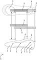
FIG. 7A shows the ballet shoe of FIG. 1 in an unassembled state;
FIG. 7B illustrates an intermediate assembly step of the ballet shoe of FIG. 6A;
FIG. 7C illustrates a further intermediate assembly step of the ballet shoe of FIG. 6A;
figure 8 shows a cross-sectional view of the ballet shoe of figure 1;
FIG. 9A shows side and bottom views of the ballet shoe of FIG. 1, illustrating placement of an embodiment of the support structure;
FIG. 9B illustrates side and bottom views of the ballet shoe of FIG. 1 showing placement of another embodiment of the support structure;
FIG. 9C illustrates the placement of some embodiments of the support structure on the ballet shoe of FIG. 1 in an unassembled state;
FIG. 10A illustrates an exemplary stylistic swatch of a support panel of the ballet shoe of FIG. 1, in a small child size;
figure 10B illustrates an exemplary style sheet for a support panel of the ballet shoe of figure 1 for a large adult size.
Detailed Description
Unless otherwise indicated, the same reference numbers and different reference numbers with the same last two digits are used to indicate the same or similar functions and/or features between the embodiments in the specification and the drawings.
The embodiments described relate to a shoe of a form suitable and/or adapted for a wide range of sports, particularly but not exclusively for use as a dance shoe, yoga shoe, pilates shoe, gym shoe, martial art shoe, climbing shoe or sports shoe. Since dance is one of the most extreme examples of the kinematic joints of the foot, dance is used herein as an exemplary athletic workout without limiting the use of the embodiments described herein.
The described embodiments relate generally to shoes or sandals suitable for use in dance, and in particular, the illustrated embodiments are suitable for use as ballet or jazz shoes. The features and functions of the described embodiments, and in particular the described flexible reinforcing structures, may also be applied to dance sports shoes, kick shoes, modern dance shoes, and other sports specialized shoes. The described embodiments may improve the aesthetic appearance of footwear that is athletic due to foot and ankle flexion, may provide increased support to the athletic foot, and may provide beneficial or therapeutic resistance to the exercising individual.
A typical footwear includes two primary elements: an upper and a sole structure. The upper provides a covering for the foot that securely receives and positions the foot with respect to the sole structure. The sole structure is secured to a lower portion of the upper and is generally positioned between the foot and the ground. In addition to reducing friction with the ground, the sole structure, together with the upper, should ideally provide support and comfort to the sole and arch of the foot.
Dance shoes are designed to complement the wide range of motion of dancers and are therefore typically made of lightweight, sexual materials. Because the design is focused on a very soft upper and sole structure, these structures generally provide little support to the foot. Typically, these shoes allow the user to easily flex the ankle and arch regions of the foot, but do not facilitate support for the ankle and arch.
Furthermore, as noted above, shoes that are allowed to bend and flex will have the side effects of wrinkling, bunching, wrinkling, drooping in the upper and outsole materials, creating undesirable interference from the ideally sought-after regular lines. Dance is a strictly regulated form of art, and any visual interference from the ideal aesthetic framework will adversely affect the overall performance of the dancer. In addition, the wrinkling, bunching, wrinkling, and sagging caused by the flexible shoe can result in the dancer feeling awkward and unsupported, which in turn affects their performance.
When the foot is standing on tiptoe, in the retracted position, the foot (on a straight line from heel to toes) is at most 20% shorter than when standing on neutral position. Muscle contraction, metatarsal contraction, causes the overall shortening of the foot. In conventional canvas ballet shoes, the canvas material shrinks with the foot and then wrinkles, bends, droops, creating an undesirable appearance.
Fig. 1 and 2 illustrate a dance shoe 100 in the form of a sandal, according to some embodiments. Footwear 100 includes an upper 102 and an outsole region 106, upper 102 defining an opening 104 to receive a wearer's foot, outsole region 106 being located beneath the sole of the foot. Outsole region 106, in combination with upper 102, defines a heel portion 110, an arch portion 120, and a forefoot portion 130 of footwear 100. The shoe 100 also includes a reinforcing structure 140 coupled to the upper 102 and the outsole region 106 and extending from about the opening 104 in the upper heel portion 112 of the heel portion 110, around the lower heel portion 114 of the heel portion 110, and through the arch portion 120 in a longitudinal direction of the shoe 100. The longitudinal direction of footwear 100 generally corresponds with the longitudinal direction of a wearer's foot.
The reinforcing structure 140 widens from adjacent the opening 104 to substantially cover the lower rear of the wearer's calcaneus bone and then narrows toward the arch portion 120. Notably, the reinforcing structure 140 is biased to form a concave shape in the arch portion 120 such that the reinforcing structure 140 in the arch portion 120 closely matches the natural curvature of the wearer's arch while substantially maintaining the smooth appearance of the upper 102 in the arch portion 120. The reinforcing structure 140 may also extend slightly or substantially into the forefoot portion 130.
Reinforcing structure 140 is attached to upper 102 and outsole region 106, specifically to upper heel portion 112 of heel portion 110, and travels downward through intermediate heel portion 113, passing through heel/outsole portion 108 around lower heel portion 114. These elements combine to provide structural support for footwear 100 with a smooth exterior finish and to substantially reduce or prevent wrinkling of upper 102, thereby conforming footwear 100 in form. Reinforcing structure 140 may be attached to upper 102 and outsole region 106 with glue or stitching, or a combination of glue and stitching. In some embodiments, the attachment of reinforcing structure 140 to upper 102 and outsole region 106 includes stitching 141 that continues just inboard of the edges of reinforcing structure 140.
According to some alternative embodiments, reinforcing structure 140 may be attached to upper 102 and outsole region 106 by a Thermoplastic Polyurethane (TPU) welding process. This may include applying a TPU film between reinforcing structure 140 and upper 102 and outsole region 106 and bonding reinforcing structure 140 to upper 102 and outsole region 106 using a fusing technique without the use of stitching. In some embodiments, the fusing technique may include using high frequency welding, laser welding, or another method of applying heat to cause bonding. According to some embodiments, the welding may be achieved by a combination of hot and cold pressing.
Embodiments of reinforcing structure 140 include a semi-rigid material having a mass that provides flexibility reinforcement and structural support to the soft and flexible footwear 100 when coupled to embodiments of footwear 100.
In some embodiments, bonding element 105 extends around an upper edge of upper 102 to define opening 104 through which the foot is received in the top of footwear 100. The bonding element 105 may be made of a cotton non-stretch material with a cotton draw tape, a cotton non-stretch material with an elastic draw tape, or an elastic bonding element without a draw tape. Bonding element 105 may be stitched, glued, or otherwise secured to upper 102 and optionally also to upper heel portion 112 of reinforcing structure 140.
Fig. 1 shows a shoe 100 to be positioned with the dancer standing flat. In this position, the foot is in its longest position and a standard dance shoe fits the foot smoothly.
Fig. 2 shows the shoe 100 in the tiptoe position. In this position, the foot muscles contract and the foot can be shortened by up to 20%. Reinforcing structure 140 is shown as a striped area, although in the illustrated embodiment, reinforcing structure 140 is not visible when not seen into footwear 100. Fig. 2 shows how stitches 141 attach reinforcing structure 140 to footwear 100, and also shows that reinforcing structure 140 extends from heel portion 110, through rear outsole 108, and into arch portion 120, to forefoot portion 130. The "cup" shape formed by the reinforcing structure 140 in the heel portion 110 and the flexible arch portion 120 provides a shoe 100 that maintains a visually smooth regular line with minimal wrinkling, bunching, or wrinkling of the fabric even when the foot is standing on its tiptoe position.
With continued reference to FIG. 2, the overall construction of the reinforcing structure 140 will be described in greater detail. Beginning with the coupling 105 atop the heel portion 110, the reinforcing structure 140 advances from the upper heel portion 112 through the middle heel portion 113. In some embodiments of footwear 100, reinforcing structure 140 covers a portion of the rear of the wearer's heel when worn and is at least wide enough to extend around the wearer's achilles tendon and/or ankle bone.
The reinforcing structure 140 continues through the medial heel portion 113 toward the lower heel portion 114, the lower heel portion 114 corresponding with a sole of the wearer's heel. The reinforcing structure 140 becomes wider as it passes through the portions 113, 114 and forms a cup-shape configured to surround the lower rear portion of the calcaneus bone of the wearer. This transition from the Achilles tendon to the sole of the foot and the corresponding gradually increasing width of the reinforcing structure 140 through the heel portion 110 is intended to serve as a gradual increase in the stiffness of the heel portion 110 as the reinforcing structure 140 approaches the sole of the foot. The level of stiffness is selected to provide flexibility, softness, and freedom of movement while still providing support, resistance, and proprioceptive feedback to the wearer. Maintaining the reinforcing structure 140 through the same width of the heel portion 110 will adversely affect the level of support, resistance, and proprioceptive feedback around the heel. In addition, the ability of the reinforcing structure 140 to reduce wrinkles on and around the heel will be compromised.
As the reinforcing structure 140 approaches the arch portion 120, the shape changes to generally mimic the transitional contour of the arch of a human foot. This requires narrowing of the reinforcing structure 140 by the heel-arch transition 160, as it is desirable to avoid excessive use of material in the arch portion 120. In particular, the reinforcing structure 140 includes a heel-arch transition portion 160 that changes from a cup shape around the heel portion 110 to a narrow portion 122 in the arch portion 120. In some embodiments, the narrow portion 122 may be elongated, similar to a strip of material, the narrow portion 122 providing reduced resistance and allowing the wearer's foot to flex more naturally than if it were cup-shaped in the heel portion 110. However, it is desirable that the reinforcing structure 140 remain wide enough in the arch portion 120 to provide support and controlled resistance as this affects the level of tactile feedback or proprioception experienced by the wearer. If the reinforcing structure 140 is too wide in the arch portion 120, it will remain "cup" shaped as seen in the heel portion 110, and this will reduce flexibility through the arch portion 120. In some embodiments, the lateral width of the lower heel portion 114 of the reinforcing structure 140 may be between about 1.8 and 3 times the lateral width through the narrow portion 122 of the arch portion 120.
In some embodiments, footwear 100 also includes a back strap 107. Straps 107 also secure reinforcing structure 140 to upper 102. Strap 107 spans from opening 104 across heel portion 110 to the arch portion, continuing under outsole 108. The back straps 107 may also continue into the arch portion 110, terminating at the front outsole 109. Strap 107 may be made of the same material as upper 102, or it may be made of other stretch or non-stretch materials, woven or non-woven material types, including the same material used for bonding element 105.
Referring again to fig. 1 and 2, footwear 100 may also include a securing device to help maintain the attachment of footwear 100 to the foot of the wearer and/or to provide adjustability of the fit of footwear 100. These securing devices may include an elastic strap attachment 146, the elastic strap attachment 146 including at least one elastic strap coupled to the upper 102 and extending across the opening 104. The at least one strap may be arranged to overlie tarsal bones of a wearer's foot when the footwear 100 is worn, and may be configured to apply tension primarily to the arch portion 120 and to apply minimal or no tension to the heel portion 110. In some embodiments, the elastic band attachment 146 may be comprised of two portions in an "X-shaped" arrangement, or as a single band, and may additionally be adjustable. The two-part "X-shaped" arrangement provides additional connectivity between the heel portion 110, the arch portion 120, and/or the forefoot portion 130 of the shoe 100. In some embodiments, the X-shaped arrangement connects the medial side of the heel portion 110 with the lateral sides of the arch or forefoot portion 120, 130 and connects the lateral sides of the heel portion 110 with the medial sides of the arch or forefoot portion 120, 130. This joins all portions of upper 201 to each other across the top of the foot, in addition to the effect of helping to reduce wrinkling and bunching of the materials used in upper 102. In other embodiments of footwear 100, laces may be used in addition to or in place of straps 146.
In some embodiments, only a single strap may be provided that extends across foot opening 104 defined by upper 102 and is coupled to upper 102 adjacent an upper edge of upper 102, similar to the location of bonding element 105. A single strap may be positioned to substantially coincide with arch portion 120 or heel-arch transition portion 160 between heel portion 110 and arch portion 120.
Referring now to FIG. 3, an exploded view of footwear 100 is shown. The shoe may also include a liner 103, a front insole 138 and a rear insole 118 to enhance comfort for the wearer. As with upper 102, liner 103 may comprise various stretch and non-stretch materials, such as canvas, leather, PU, lycra, mesh, neoprene, cotton. Liner 103 may also include buoyant materials such as foam and its variants and rubber and its variants. Liner 103 may be very light and thin, with a soft feel to provide comfort, while reducing the bulk of footwear 100. Reinforcing structure 140 may be located on the top or under liner 103, or between liner 103 and upper 102. In some embodiments, it may be desirable to conceal reinforcing structure 140, or to place reinforcing structure 140 visible, for example, on the exterior of upper 102.
The shape of the rear insole 118 and the front insole 138 generally match the overall shape of the rear insole 108 and the front insole 109. Rear insole 118 and front insole 138 are attached to one or more of upper 102, liner 103, and reinforcing structure 140, for example, by stitching or by adhesive.
The connection formed by bonding the reinforcing structure 140 to the shoe 100 is important because it means that the shoe 100 is semi-rigid but flexible between the heel portion 110, the outsoles 108, 109 and the arch portion 120. Particularly for lightweight ballet shoes, reinforcing structure 140 provides structure to shoe 100, helps upper 102 maintain its shape and regular lines during movement, and helps the form fit appearance and shape of shoe 100. Reinforcing structure 140 also allows footwear 100 to support the wearer's foot and ankle by retaining the body of semi-rigid material on the foot and thereby provide controlled resistance to muscular activity. The shape and positioning of the reinforcing structure 140 is also important to achieve the desired structural and aesthetic effects. As disclosed herein, the reinforcing structure 140 provides advantages to the wearer such as proprioceptive feedback in some embodiments.
Fig. 4A and 4B illustrate top and bottom views, respectively, of the shoe 100, particularly illustrating the shape and location of the reinforcing structure 140 relative to the shoe 100. For clarity, the belt 146 is not shown. Fig. 4A is a view into shoe 100. Reinforcing structure 140 is visible in fig. 4A, and in this embodiment of footwear 100, reinforcing structure 140 is attached to upper 102 by stitching along or near the edges of reinforcing structure 140. These stitches form a stitch line 141 that generally follows the contour of the reinforcing structure 140. In fig. 4B, which is a view of the bottom of the shoe 100 from the outside, the reinforcing structure 140 is not visible. However, the suture 141 is visible, indicating the position of the reinforcing structure 140. Fig. 4C and 4D are alternative top views of fig. 4A, according to alternative embodiments, and illustrate the positioning of reinforcing structure 140 relative to the remainder of footwear 100, as if upper 102 were transparent.
With continued reference to all figures: fig. 4A, 4B, 4C, and 4D. The reinforcing structure 140 narrows as the reinforcing structure 140 transitions from the heel portion 110 to the arch portion 120 via the heel-arch transition 160. In embodiments where the reinforcing structure 140 extends from the arch portion 120 into the forefoot portion 130, the reinforcing structure 140 includes an arch-forefoot transition 170 that extends to meet the outsole 109.
In some embodiments, the reinforcing structure 140 flares or widens from the narrow portion 122 into a Y-shaped configuration in the arch-forefoot transition 170, with portions of the arch-forefoot transition 170 extending at least partially around the sides of the front outsole 109, as best shown in fig. 4C. In some embodiments of the arch-forefoot transition 170, the reinforcing structure 140 gradually widens to about 1.5 to 3 times the width of the narrowest portion of the reinforcing structure 140. The gradual widening provided by the arch-forefoot transition 170 reduces wrinkling, creasing, and bunching of the surrounding material of the upper 102, and also improves the connection between the forefoot portion 130 and the arch portion 120, which is advantageous in improving the overall torsional stiffness of the footwear 100, or at least reducing undesirable sliding or movement of the wearer's foot and upper 102 relative to the outsole 109 during use.
In some embodiments, the reinforcing structure 140 flares or widens from the narrow portion 122 in the arch-forefoot transition 170 and extends to substantially cover the forefoot portion 130, extending to the edge of the forefoot outsole 109, as best shown in fig. 4D. The reinforcing structure 140 extending over substantially all of the front outsole 109 such that the reinforcing structure extends under the wearer's forefoot and ankle bones may have advantages such as helping to keep the front outsole 109 smooth under the foot and acting as a shock absorber under the wearer's ankle bones.
For a fixed length of the heel and forefoot portions 110, 130, the length of the narrow portion 122 affects the transition in the heel-arch transition 160 and/or the arch-forefoot transition 170. This shortens the length of the transitions 160, 170 if the narrow portion 122 substantially spans the length of the arch region 120, while a shorter narrow portion 122 results in longer transitions 160, 170. Longer transitions 160, 170 allow the width change in these portions to occur more gradually over the length of the foot, and due to the shorter narrow portion 122, the bending stiffness of the arch portion 120 and its ability to provide arch support to the wearer when the wearer's foot is standing on tiptoe may be improved. Further, such a configuration may increase the torsional stiffness of arch portion 120 and, thus, may result in reduced lateral twisting of the wearer's foot and ankle.
Referring now to fig. 5, which illustrates the reinforcing structure 140 in more detail, the reinforcing structure 140 includes a heel portion 142, an arch portion 143, and a forefoot portion 144. Heel portion 142 corresponds with heel portion 110 of footwear 100, arch portion 143 corresponds with arch portion 120 of footwear 100, and forefoot portion 144 corresponds with forefoot portion 130 of footwear 100. In embodiments where the reinforcing structure 140 extends into the forefoot portion 130, the forefoot portion 144 has extensions 145 that extend to either side of the forward outsole 109 in a generally Y-shaped configuration.
The reinforcing structure 140 includes a convex shape in the heel portion 142 as viewed from the lateral side of the shoe to form a cup around the heel of the wearer. From the exterior of the shoe, the reinforcing structure 140 transitions to a concave shape in the arch portion 143 to support the arch of the wearer's foot. In some embodiments, the concave shape of the reinforcing structure 140 in the arch portion 143 extends substantially into the forefoot portion 144. By extending the concave shape substantially into the forefoot portion 144, the forefoot portion 144 of the reinforcing structure 140 is biased to generally align with the sole of the wearer when the wearer stands on their foot, as shown, for example, in fig. 2. This maintains the form-fitting appearance and shape of the shoe 100, and the connection of the shoe 100 and the wearer's foot when they stand on tiptoe. This may also reduce bunching or buckling of shoe material in the forefoot portion 144 and provide the shoe 100 with a smooth and streamlined appearance when the wearer stands on tiptoe. Furthermore, the reinforcing structure 140 is sufficiently flexible such that when the wearer places weight on the forefoot portion 144 (e.g., in a pronation), the concave shape extending into the forefoot portion 144 is able to bend into a convex shape, maintaining the same (or similar) smooth and streamlined appearance when the wearer stands on their foot.
In some embodiments, the reinforcing structure 140 may be biased to transition from a concave shape in the arch portion 143 to a slightly convex shape in the forefoot portion 144 to conform to the shape of the wearer's forefoot. This embodiment of the reinforcing structure 140 has a contoured profile when viewed from the side, as it changes from a convex profile in the heel to a concave profile in the arch and again to a slightly convex profile in the forefoot. The contoured profile changes from a convex profile in the heel to a concave profile in the arch through a first inflection point, the location of which generally corresponds to the heel-arch transition 160. The first inflection point may be substantially coincident with an ankle of the wearer. Similarly, the contoured profile changes from a concave profile in the arch to a slightly convex profile in the forefoot with a second inflection point, the location of which generally corresponds to the arch-forefoot transition 170. The second inflection point may be substantially coincident with an ankle bone of the wearer.
In some embodiments, the reinforcing structure 140 is formed from a plurality of pieces, wherein each of the plurality of pieces is referred to as a support panel 150. Each support panel 150 may have the same size and/or shape and may be made of the same material. Alternatively, different sizes, shapes, and/or materials of the support panel 150 may be combined, adjusting the characteristics of the reinforcing structure 140.
Fig. 5 shows an embodiment of a reinforcing structure 140 comprising two support panels 150, respectively support panel 150A and support panel 150B, which are connected by a stitch line 148. In this embodiment, the support panels 150 are arranged such that one of the panels 150 corresponds to the inside of the wearer's foot and the other of the panels 150 corresponds to the outside of the wearer's foot. The inboard and outboard support panels 150A, 150B may be identical or mirror images of each other. However, in other embodiments of the reinforcing structure 140, the support panels 150 on the inner side may be different from the support panels 150 on the outer side. This may, for example, allow embodiments of panel 150 to accommodate differences between different portions of a wearer's foot, such as differences between the medial and lateral sides of the foot, or differences between the left and right feet thereof.
Fig. 6 shows a panel 150A, which is similar to panel 150B, being a flat piece prior to being joined to form the reinforcing structure 140. In this embodiment, the panels 150A and 150B are at least substantially identical in shape and size. Panel 150A includes a first edge 151A that includes a first heel edge 152A, a first arch edge 153A, a first forefoot edge 154A. When positioned within footwear 100, first edge 151A continues along a central longitudinal axis of outsole region 106. The first heel edge 152A corresponds to the heel portion 142 of the reinforcing structure 140 and is connected to a first arch edge 153A corresponding to the arch portion 143 of the reinforcing structure 140. The first arch edge 153A is connected to a first forefoot edge 154A, the first forefoot edge 154A corresponding to the forefoot portion 144 of the reinforcing structure 140. First forefoot edge 154A may also include an extension edge 155A, which extension edge 155A corresponds to extension 145 of reinforcement structure 140, which extends either side of forefoot outsole 109 in a generally Y-shaped configuration.
The first edge 151A has a wavy profile corresponding to the wavy profile of the reinforcing structure 140 shown in fig. 5. Specifically, first heel edge 152A includes a convex shape and first arch edge 153A includes a concave shape. The first edge 151A transitions between convex and concave shapes via an inflection point, the location of which generally corresponds to the location of the heel-arch transition 160 and may generally coincide with the ankle of the wearer. First forefoot edge 154A may also have a concave shape, and first edge 151A may transition between concave shapes via an inflection point, the location of which generally corresponds to the location of arch-forefoot transition 170, and which may generally conform to the wearer's anklebones.
With arch portion 143, the distance between first edge 151A and second edge 156A remains substantially constant such that first arch edge 153A and second arch edge 158A may be substantially parallel. As first edge 151A and second edge 156A separate, providing greater support under the wearer's forefoot, the distance begins to increase through arch-forefoot transition 170.
Since in this embodiment the panel 150A is at least substantially identical in shape and overall impression to the panel 150B, the panel 150B further comprises a first edge 151B, the first edge 151B comprising a heel edge 152B, a second edge 156B, etc., wherein like reference numerals refer to like parts.
The panels 150, 150A, 150B may be formed from a variety of different materials. Some embodiments include EVA foam. Such materials may also include rubber, such as natural or synthetic rubber (although synthetic rubber is preferred), in combination with EVA foam. The EVA foam and rubber may be provided in approximately equal proportions, or the material may be composed of 40% to 60% EVA, 40% to 60% rubber, and 0% to 20% other materials. In some embodiments, different proportions of EVA and rubber may be used, with one of these components ranging to, for example, 80% or 90%, with the remainder comprising the other components or other materials. In some embodiments, EVA foam may be used without any rubber.
Fig. 7A, 7B, and 7C schematically illustrate some steps of an exemplary manufacturing and assembly process for footwear 100, including the application of reinforcing structures 140 as described with respect to some embodiments of footwear 100. Similar structural principles apply to the different embodiments of footwear 100 described herein. Upper 102 is cut into a flat pattern comprising opposing halves, and liner 103 is then applied thereto. Panel 150A and panel 150B (e.g., as shown in fig. 6) are then attached to upper 102 and liner 103 (not shown) to obtain the piece shown in fig. 7A. In this embodiment, panel 150A and panel 150B are identical and mirror images of each other and are attached to the medial and lateral sides of the upper. Panels 150A, 150B may be attached by gluing or stitching panels 150A, 150B to liner 103 or upper 102, or by a combination of gluing and stitching. Fig. 7A shows panels 150A, 150B attached to upper 102 by stitch lines 141, stitch lines 141 along or adjacent second edges 156A, 156B.
Fig. 7B shows an intermediate step in the assembly process, in which the two panels 150A and 150B are brought towards each other (as indicated by the dashed arrows) to achieve the connection by folding the piece of fig. 7A along the longitudinal axis of the shoe 100. This axis generally corresponds to the elongated axis of the wearer's foot. In particular, panels 150A, 150B are joined along first edges 151A, 151B thereof, and may be joined by stitching, such as by center stitching 148, to form reinforcing structure 140 and footwear 100 as shown in fig. 7C.
In some embodiments, panels 150A and 150B may be further secured along and adjacent to their first edges 151A, 151B by additional stitching with strap 107, both inside of footwear 100 and outside of footwear 100, to arrive at the embodiment shown in fig. 4A and 4B. The outsoles 108, 109, insoles 118, 138 and straps 146 may then be applied. It should be noted that with respect to some embodiments, the steps of the construction process disclosed herein may be performed in a different order; for example, panels 150A and 150B may be assembled separately to upper 102 to form reinforcing structure 140 shown in fig. 5 and then inserted through opening 104 in the manner of a sock liner.
In some embodiments, reinforcing structure 140 is attached to upper 102 by stitching and/or adhesives. Stitching 141 attaches the semi-rigid material from the top of the heel portion, extends down and forward along a line through the side or rear of the shoe, and extends into and through the arch portion. Stitching 141 joins reinforcing structure 140 to one or both of upper 102 and liner 103. The straps 107 are generally along the longitudinal direction of the footwear 100. The straps 107 continue from the top of the heel portion 110 along the centerline of the shoe 100 and into the arch portion 120. Reinforcing structure 140 continues through arch portion 120 and into forefoot portion 130 to join forefoot outsole 109, thereby forming a semi-rigid, yet flexible, support structure for footwear 100.
In embodiments where an adhesive is used in addition to or in lieu of stitching, a suitable adhesive is a polychloroprene-toluene adhesive, such as manufactured by Hongli resin manufacturing Limited, which contains 20% to 25% polychloroprene and 60% to 75% toluene. Polychloroprene-toluene adhesives bond quickly, resist higher temperatures, and can provide strong bonds between materials such as leather and neoprene. Alternatively, a silicon-based adhesive may be used. Silicone adhesives have elasticity over a wide temperature range, which is advantageous if the dancer subjects his footwear to frequent and robust movements.
In the depicted embodiment, when the foot is in motion for bending and flexion, the excess shoe material created by the foot flexion will travel forward and backward to the ends of the shoe 100, leaving a regular line under the arch and around the heel. The presence of the semi-rigid material integrally attached to wrap around the heel and extend through the arch of the foot increases the level of support for the foot and ankle and provides controlled resistance. The reinforcing structure 140 may also provide a proprioceptive effect in which the wearer experiences improved tactile feedback, which may provide benefits such as improved perception of their foot position. Such tactile feedback may help remind the wearer to work their foot against the floor (increasing muscle strength) and/or to put their lower leg in neutral alignment (reducing the likelihood of pronation and/or supination of the foot).
Fig. 8 shows a cross-sectional view of the assembled shoe 100. The contoured profile of the first edges 151A, 151B means that when the concave and convex edges are connected, the reinforcing structure 140 is biased to form concave and convex surfaces in the heel 142, arch 143, and forefoot 144 without external support or structure. In other words, the convex and concave edges provide lateral and longitudinal curvature around the back, bottom, and sides of the heel such that heel portion 110 has a cup-like shape that generally conforms to the contour of the wearer's heel without the need for a mold. Similarly, the convex and concave edges surround the curvature in the lateral and longitudinal directions of the back, bottom, and sides of arch portion 120 such that arch portion 120 is biased to have a concave shape when footwear 100 is assembled by stitching first edges 151A, 151B together. This means that the arch portion 120 generally follows the contours of the dancer's arch when the shoe is worn, without the need for a mold to pre-form the shoe.
In some embodiments, the cumulative effect of incorporating the cup-shape of the heel and arch profile into the geometry of panels 150A, 150B may at least reduce the need for external support structures to achieve such shoe shapes, particularly in arch portion 120, and thus may reduce bulk. A smaller volume shoe may have the advantages of lighter weight, improved foot flexibility, or providing the wearer with an improved "feel" or "connection" to the floor, which may have benefits with respect to dance techniques and performance.
Each panel 150A, 150B may be formed from a single sheet of material. In some embodiments, different pieces and types of materials having different material properties may be used to form, for example, a semi-rigid material through heel portion 110 and arch portion 120. In doing so, this may provide different levels of resistance in different portions of footwear 100, thereby adjusting the level of proprioceptive feedback.
The level of proprioceptive feedback through the arcuate portion 120 can be adjusted by adding additional support or stiffening structure, as shown in fig. 9A and 9B. According to some embodiments, as shown in fig. 9A, a small, thin, elongated flexible plate 180 may extend through arch portion 120 and into heel portion 110 and forefoot portion 130 at the edges without extending through these portions. In other embodiments, the plate 180 extends through the arch portion 120 and the heel portion 110, where it may extend to the opening 104. The purpose of plate 180 is to supplement reinforcing structure 140 with arch portion 120, provide greater resistance to foot flexion and provide additional support to the arch. The amount of resistance and the amount of arch support can be varied by changing the size of the plate 180.
The flexible plate 180 may have a lateral width that is approximately the same as or within about 20% of the width of the semi-rigid material of the reinforcing structure 140 through the arch portion 120. The flexible sheet 180 may be positioned along or slightly offset from a longitudinal direction (e.g., a centerline) of the footwear 100.
The board 180 may comprise a pulp board material, such as "tarragon board" manufactured by tarragon international group, or a similar board material. The thickness of the plate 180 may be about 0.5mm to about 0.8mm, and optionally about 0.6 mm. The plate 180 may be generally rectangular or slightly trapezoidal, or have slightly curved or flared ends.
In some embodiments, a second plate 185 may be used in conjunction with the plate 180. Referring to fig. 9B, in some embodiments, plate 180 and/or plate 185 extend into forefoot portion 110 and may extend below the wearer's anklebones. By extending the panel 180 and/or the panel 185 into the forefoot portion 110, the reinforcement provided by the panel 180, 185 continues into the forefoot portion 110 and is able to follow the contours of the wearer's foot along most of the length of the wearer's foot. In particular, this provides support when the wearer's feet are in a ballet toe stance position.
Some embodiments may use the polychloroprene-toluene adhesive or silicone adhesive described above to couple the second plate 185 to the plate 180. The second plate 185 may be of a similar material as the plate 180, and in some embodiments the second plate 185 spans substantially the length of the arch portion 120 and may extend further into and/or through the heel portion. Such a configuration may provide improved arch support, improved torsional stiffness in arch portion 120, or at least improve the resilience of footwear 100 such that its shape in arch portion 120 lasts longer.
In embodiments where one or both of the plates 180, 185 extend into the forefoot portion 130, the plates 180 and/or 185 follow the contours of the wearer's foot when the wearer stands on his or her foot. When upper 102 and/or liner 103 are connected to plate 180, this causes upper 102 and/or liner 103 to follow the shape of plate 180, plate 185, and the shape of the wearer's foot. Advantageously, this may reduce wrinkling, creasing, bunching, or bending of the upper/liner material in the forefoot portion 130 and around the forefoot outsole 109, particularly when standing on tiptoe, resulting in a more streamlined, aesthetically pleasing appearance of the footwear 100.
As previously mentioned, the semi-rigid material of the reinforcing structure 140 used in embodiments including one or more plates 180, 185 may be the same in terms of its proportions, positioning, construction, and material properties as described with respect to other embodiments of the footwear 100.
Here, the concavity measure in arch portion 120 is represented by arch measurement Q, which is the maximum vertical distance between measurement line 200 (as explained below with reference to fig. 10A and 10B) and first edge 151. The greater the vertical distance, the more concave the arch portion 540. The more concave arch portion 120 provides a tighter fit in at least the arch portion 120, which may provide comfort, support, and/or improved proprioception for the wearer. As previously described, improved support and/or proprioception may provide a wearer with improved awareness of their foot position and technique, e.g., with respect to foot pronation, and thus may help, e.g., prevent injury and/or injury recovery. Further, the improved fit may provide an aesthetic benefit in the appearance of a more streamlined fit, while reducing indentation, bunching, or wrinkling of upper 102, particularly when the wearer's foot is on tiptoe.
In embodiments where the curvilinear profile of arch portion 120 is at least substantially concave, the curvilinear profile may approximate an arc of radius R and R. Where R is determined using a simple algebra once the dimensions Q and Y are known. Specifically, the method comprises the following steps:

fig. 10A shows an embodiment of a panel 150 for a child-sized 7 shoe 100. The distance P is 45mm, S is 24.5mm, T is 28mm, V is 16mm, W is 14.5mm, Q is 5.5mm, X is 32mm, Y is 66mm, and Z is 25 mm. The concave arch portion 540 is an arc with a radius R of 101.75 mm. In some embodiments, the reinforcing material 140 in the arch portion is biased to have a concave shape when the footwear is not worn, wherein Q may be as low as about 3 mm. P, S, W, Q, X, Y, Z, R generally represents the lower end of the range of values for P, S, W, Q, X, Y, Z, R.
Fig. 10B illustrates an embodiment of a panel 150 for an adult sized shoe 100. The distance P is 78mm, S is 47.5mm, T is 41mm, V is 21mm, W is 17mm, Q is 11.5mm, X is 59mm, Y is 133mm, and Z is 39 mm. The concave arch portion 540 is an arc with a radius R of 198 mm. In some embodiments, the reinforcing material 140 in the arch portion is biased to have a concave shape when the footwear is not worn, wherein Q may be up to about 25 mm. P, S, W, Q, X, Y, Z, R roughly represent the upper end of the range of values for P, S, W, Q, X, Y, Z, R.
Some embodiments of the shoe may be made in youth sizes, which typically fall between the largest child shoe size and the smallest adult shoe size.
P, S, T, V, W, Q, X, Y, Z, R is by way of example only and is intended to provide an indication of the proportions of panels 150A, 150B. These values are summarized in the table below.

The shoe material must also be able to bend and flex with the foot's motion to achieve a balance between structure and flexibility. A balance between these variables is required to achieve the desired effect. An example of a material that may accomplish this, which in some embodiments is Ethylene Vinyl Acetate (EVA) foam. EVA foam is available in a wide range of grades, varying in both thickness and density.
Examples of other materials that may achieve acceptable results as a flexible reinforcing material include other foam variants such as, but not limited to, polyurethane foam, polyethylene foam, cross-linked polyethylene foam, high density microcellular foam, and closed cell PVC foam. Such different thickness and density levels of material provide a wide range of options for implementing the described embodiments. The foam has excellent buoyancy properties and provides a good balance between structure, flexibility, and resistance. The foam also provides cushioning properties, further enhancing wearer comfort. Other flexible stiffening materials that may be employed in embodiments include, but are not limited to: felts, non-woven bonded synthetic fibers, counter-balancing materials and fiberboards, sponge rubber, rubber (natural, neoprene, SBR, butanol, nitrite or nitrile rubber, silicone and urethane), cork, flocked fabric and paper (or other cellulose-based materials).
For ballet embodiments, upper 102 and liner 103 together may be about 1mm to about 4mm thick, excluding the outsole or semi-rigid material in reinforcing structure 140. In order to maintain a smooth finish with minimal disruption in footwear 100, a thickness of the semi-rigid material in reinforcing structure 140 ranging from about 2mm to about 4mm is considered suitable. The desired thickness is determined by the type of shoe being constructed. For example, ballet shoes with a delicate soft structure may require a thin 2mm foam. Thicker EVA foam may be required as the shoe design naturally becomes more structured. For example, a jazz shoe may use 3mm EVA foam, while a kick or dance shoe may use 4mm EVA foam.
About 30kg/m at an EVA foam thickness of 2mm to 4mm3To about 60kg/m3Is believed to provide the proper balance of flexibility, support and comfort. Some variation in the thickness and density of the EVA foam may also produce acceptable results. For example, if the EVA foam is kept thin (e.g., 2 mm-3 mm), the density can be raised to 75 to 105kg/m3Or even up to 120kg/m3. In some embodiments, the foam material may include EVA blended or otherwise bonded with a rubber material, such as a synthetic rubber material.
The maximum thickness of the ballet shoe embodiment, e.g., comprising an insole, a lining, a semi-rigid material, an exterior material (which may effectively be part of the upper), and an outsole, preferably does not exceed about 8-10 mm, and is preferably less than about 6 mm.
Various embodiments have been described herein in connection with various different configurations, arrangements, features, and functions of the dance shoe depicted. These embodiments are intended to encompass various combinations of these features, functions, configurations, and arrangements depicted, as may be appropriate for the type of dance shoe in question. For example, while the embodiment of the shoe shown in FIG. 1 shows a ballet shoe having straps arranged in an X-shape, it should be understood that other ballet shoe embodiments described herein may have only a single strap. Likewise, the arrangement of strap 146 with a longitudinally shortened space between its attachment point to upper 102 and a location generally coincident with arch portion 120 and/or heel-arch transition region 160 may be applied to other ballet shoe embodiments described herein. Additionally, while an exploded view has been provided to illustrate the construction of some of the shoes described herein, this is provided by way of example and not limitation, as an illustrative guide to the construction of the embodiments.
The semi-rigid materials used in the heel portions described herein are generally more flexible, softer, and of lower density than standard heel stabilizers, thereby readily allowing the foot to flex without uncomfortably striking the skin or structures of the foot around the heel or arch.
The depicted embodiment also increases the level of foot and ankle support by applying a semi-rigid material to areas of footwear 100 that are intended to support the foot, such as the heel, arch, and outsole areas. This creates a flexible connection between the heel of the shoe 100, the outsole of the shoe 100, and the arch of the shoe 100, providing more structure and body and then more support to the shoe 100, which has a proprioceptive effect. The use of a semi-rigid material provides a form-fitting appearance and shape to footwear 100. This provides a proprioceptive connection for the wearer so that the wearer can increase awareness of their feet, particularly when their feet are engaged with a contact surface such as a stage.
This same semi-rigid material also provides controlled resistance to the foot muscles when undergoing flexion or point movements through the thin flexible connection between the heel, outsole and arch of the shoe 100. This controlled resistance may cause the muscle strength to increase over time. The application of the flexible reinforcing structure 140 around the heel and arch portions may also improve the comfort of the dance shoe, which may increase the confidence or ease of the dance user during the sport.
Note that recitation of ranges of values herein are intended to serve as a shorthand method of referring individually to each separate value falling within the range. Unless otherwise indicated herein, each individual value is incorporated into the specification as if it were individually recited herein.
Although embodiments are described herein in specific detail, it should be understood that such embodiments are described by way of example, and should not be construed to limit or restrict the scope of the application with respect to equivalents.
Throughout this specification the word "comprise", or variations such as "comprises" or "comprising", will be understood to imply the inclusion of a stated element, integer or step, or group of elements, integers or steps, but not the exclusion of any other element, integer or step, or group of elements, integers or steps.
Any discussion of documents, acts, materials, devices, articles or the like which has been included in the present specification is not to be taken as an admission that any or all of these matters form part of the prior art base or were common general knowledge in the field relevant to the present disclosure as it existed before the priority date of each appended claim.
Claims (42)
1. A dance shoe comprising:
an upper defining an opening for receiving a foot;
an outsole region located beneath a sole of the foot and defining, in combination with the upper, a heel portion, an arch portion, and a forefoot portion; and
a reinforcing structure coupled to the upper and the outsole region and including a convex portion extending around a lower portion of the heel portion from proximate the opening in an upper portion of the heel portion and a concave portion passing through the arch portion in a longitudinal direction of the shoe, the reinforcing structure widening from proximate the opening, substantially covering a lower rear portion of a wearer's calcaneus bone, and then narrowing toward the arch portion;
wherein the reinforcing structure is formed by first and second panels corresponding to the medial and lateral sides of the wearer's foot, the first and second panels each comprising a first edge comprising a convex edge and a concave edge, such that when the first edges are connected to each other, the convex and concave edges form the convex and concave portions of the reinforcing structure; and
wherein the concavity in the arch portion biases the reinforcing structure in the arch portion to closely match the curvature of the wearer's arch while substantially maintaining a smooth appearance of the upper in the arch portion.
2. The shoe of claim 1, wherein the concavity in the arch portion includes a vertex that rises between 3mm and 25mm from the heel.
3. The shoe of claim 1, wherein the concavity in the arch portion includes a vertex that rises between 4mm and 20mm from the heel.
4. The shoe of claim 1, wherein the concavity in the arch portion includes a vertex that rises between 4mm and 15mm from the heel.
5. The shoe of claim 1, wherein the concavity in the arch portion includes a vertex that rises between 5mm and 12mm from the heel.
6. The shoe of any of claims 1-5, wherein the first panel and the second panel each comprise a flat.
7. A shoe according to any one of claims 1 to 6 wherein said convex and concave edges comprise a substantially convex edge in said heel portion and a substantially concave edge in said arch portion such that when the pattern is assembled by coupling the two halves along said convex and concave edges by a coupling device, said heel portion forms said convex portion to substantially cover the calcaneus bone and said arch portion forms said concave portion.
8. The shoe of claim 7, wherein the convex and concave edges further comprise a substantially convex edge in the forefoot portion, such that when the pattern is assembled, the forefoot portion forms a convex shape that conforms to the shape of the wearer's forefoot.
9. A shoe according to claim 7 or 8 wherein the coupling device comprises a plurality of stitching to abut the edges of each half with one another.
10. A shoe according to claim 7 or 8 wherein said coupling device comprises adhesive to abut the edges of each half against each other.
11. The shoe of any one of claims 1 to 10, wherein the upper is thin and flexible.
12. The shoe of any of claims 1-11, wherein the reinforcing structure extends through the arch portion and into the forefoot portion.
13. A shoe according to any one of claims 1 to 12, wherein said reinforcing structure comprises a semi-rigid material.
14. The shoe of any of claims 1-13, wherein the reinforcing structure widens slightly as it transitions from the arch portion to the forefoot portion.
15. The shoe of claim 14, wherein the slight widening forms a Y-shaped configuration in the forefoot portion.
The shoe of claim 14, wherein the reinforcing structure extends to substantially cover the forefoot portion.
16. The shoe of any one of claims 1-15, further comprising a strap secured to the upper and extending along a longitudinal centerline of the shoe from the upper of the heel portion to the forefoot portion, the strap coinciding with a central longitudinal seam extending through the outsole to the forefoot portion.
17. A shoe according to any one of claims 1 to 16, wherein said reinforcing structure has a thickness of between 2mm and 4 mm.
18. An item of footwear as claimed in any one of claims 1 to 17, wherein the reinforcing structure comprises a foam material.
19. The shoe of claim 18, wherein the foam material comprises Ethylene Vinyl Acetate (EVA) foam.
20. A shoe according to claim 18 or 19, wherein said foam material consists essentially of EVA foam and rubber.
21. The shoe of claim 17, wherein the foam material comprises about 40% to 60% by weight EVA foam, about 40% to 60% by weight rubber, and 0% to 20% other materials.
22. A shoe according to claim 20 or 21, wherein said rubber is a synthetic rubber.
23. A shoe according to any one of claims 1 to 22, wherein the reinforcing structure is supported by the first plate.
24. The shoe of claim 23, wherein the first plate is thin, flexible, elongated, and extends through the arch portion.
25. A shoe according to claim 23 or 24, wherein said first plate is positioned in a longitudinal direction of the shoe.
26. The shoe of any of claims 23-25, wherein the first plate has a thickness of about 0.5mm to about 0.8 mm.
27. An item of footwear as claimed in any one of claims 23 to 25, wherein the thickness of the first plate is about 0.6mm
28. An article of footwear according to any one of claims 23 to 27, wherein the first plate extends into the forefoot portion to underlie an ankle bone of the wearer.
29. An article of footwear according to any one of claims 23 to 28, wherein the first plate extends through the heel portion.
30. An article of footwear according to any one of claims 23 to 29, wherein the reinforcing structure is further supported by a second panel connected to the first panel.
31. A shoe according to claim 30, wherein said first and second boards are made of a pulp board material.
32. The shoe of any of claims 1-31, wherein the reinforcing structure comprises a material selected from the group consisting of: a non-woven bonded synthetic fiber material; a counterbalance material; a fiberboard; sponge rubber; natural rubber; chloroprene rubber; styrene Butadiene Rubber (SBR); butyl rubber; silicone rubber; nitrile rubber; a urethane rubber; a polyurethane foam; cork wood; a cellulosic material; ethylene-vinyl acetate (EVA) foam; a polyethylene foam; a crosslinked polyethylene foam; a high density microcellular foam; and closed cell polyvinyl chloride foam.
33. The shoe of claim 32, wherein the EVA foam has a density of about 30kg/m3 to about 120kg/m 3.
34. The shoe of any one of claims 1-33, wherein the material of the upper comprises one or more of: leather; polyurethane (PU) leather; canvas; raising a suede surface; cotton; nylon; lycra; mesh and spandex.
35. A shoe according to any one of claims 1 to 34, wherein said shoe is a ballet shoe.
36. The shoe of claim 35, further comprising at least one elastic band coupled to the upper and extending through the opening, the at least one band being arranged to cover tarsal bones of the foot when the shoe is worn and to apply tension primarily to the arch portion and to apply minimal or no tension to the heel portion.
37. A shoe according to any one of claims 1 to 36, wherein said shoe is a split-sole shoe.
38. A method of manufacturing a dance shoe, comprising:
coupling a reinforcing structure to opposing halves of an upper, the reinforcing structure including two portions configured to abut along mating concave edges; and
joining the opposing halves of the upper along the mating concave edges of the reinforcing structure such that the reinforcing structure forms a concave shape corresponding to the arch of the wearer.
39. The method of claim 38, wherein the reinforcing structure is made of a semi-rigid material.
40. A method according to claim 38 or 39, wherein joining the opposite halves of the upper along the matching concave edges of the reinforcing structure forms a shoe having a heel portion, a concave arch portion and a forefoot portion.
41. The method according to any one of claims 38 to 40, further comprising attaching at least one elongate flexible sheet to the shoe along a central longitudinal axis of the shoe.
42. The method of claim 40 or claim 41 as dependent on claim 40, further comprising attaching a forefoot outsole to the forefoot portion and a rearfoot outsole to the heel portion.
Applications Claiming Priority (5)
| Application Number | Priority Date | Filing Date | Title |
|---|---|---|---|
| AU2019902214 | 2019-06-25 | ||
| AU2019902214A AU2019902214A0 (en) | 2019-06-25 | Method and structure for making dance footwear | |
| AU2019903671 | 2019-09-30 | ||
| AU2019903671A AU2019903671A0 (en) | 2019-09-30 | Method and structure for making dance footwear | |
| PCT/AU2020/050638 WO2020257850A1 (en) | 2019-06-25 | 2020-06-24 | Method and structure for making dance footwear |
Publications (1)
| Publication Number | Publication Date |
|---|---|
| CN114286629A true CN114286629A (en) | 2022-04-05 |
Family
ID=74059595
Family Applications (1)
| Application Number | Title | Priority Date | Filing Date |
|---|---|---|---|
| CN202080059971.7A Withdrawn CN114286629A (en) | 2019-06-25 | 2020-06-24 | Method and structure for making dance shoes |
Country Status (2)
| Country | Link |
|---|---|
| CN (1) | CN114286629A (en) |
| WO (1) | WO2020257850A1 (en) |
Citations (6)
| Publication number | Priority date | Publication date | Assignee | Title |
|---|---|---|---|---|
| CN1151850A (en) * | 1995-10-12 | 1997-06-18 | 芭蕾制造商公司 | Dance shoe sole |
| US20060196079A1 (en) * | 2005-03-01 | 2006-09-07 | Ballet Makers, Inc. | Split sole dance shoe having enhanced flexibility and support |
| US20130104420A1 (en) * | 2010-03-24 | 2013-05-02 | Timothy Charles Heathcote | Dance shoes with improved heel and arch sections |
| CN105283090A (en) * | 2012-07-21 | 2016-01-27 | 乔泽特·哈佐里 | dancing shoes |
| CN108968227A (en) * | 2017-06-01 | 2018-12-11 | 维奥尼克集团有限公司 | Footwear and its manufacture |
| CN208403410U (en) * | 2018-06-07 | 2019-01-22 | 北京孝夕阳科技发展有限公司 | Wide pump |
Family Cites Families (4)
| Publication number | Priority date | Publication date | Assignee | Title |
|---|---|---|---|---|
| US2598782A (en) * | 1949-11-04 | 1952-06-03 | George H Gillis | Track shoe with cushioned heelreceiving pocket |
| GB2232057A (en) * | 1989-05-26 | 1990-12-05 | Burlington Int Group | Dancer's shoe |
| GB2245813B (en) * | 1990-07-09 | 1994-08-24 | Dancing Bonzai Co | Ballet shoe |
| GB9819034D0 (en) * | 1998-09-02 | 1998-10-28 | Rem S Srl | Manufacture of article of footwear |
-
2020
- 2020-06-24 WO PCT/AU2020/050638 patent/WO2020257850A1/en not_active Ceased
- 2020-06-24 CN CN202080059971.7A patent/CN114286629A/en not_active Withdrawn
Patent Citations (6)
| Publication number | Priority date | Publication date | Assignee | Title |
|---|---|---|---|---|
| CN1151850A (en) * | 1995-10-12 | 1997-06-18 | 芭蕾制造商公司 | Dance shoe sole |
| US20060196079A1 (en) * | 2005-03-01 | 2006-09-07 | Ballet Makers, Inc. | Split sole dance shoe having enhanced flexibility and support |
| US20130104420A1 (en) * | 2010-03-24 | 2013-05-02 | Timothy Charles Heathcote | Dance shoes with improved heel and arch sections |
| CN105283090A (en) * | 2012-07-21 | 2016-01-27 | 乔泽特·哈佐里 | dancing shoes |
| CN108968227A (en) * | 2017-06-01 | 2018-12-11 | 维奥尼克集团有限公司 | Footwear and its manufacture |
| CN208403410U (en) * | 2018-06-07 | 2019-01-22 | 北京孝夕阳科技发展有限公司 | Wide pump |
Also Published As
| Publication number | Publication date |
|---|---|
| WO2020257850A1 (en) | 2020-12-30 |
Similar Documents
| Publication | Publication Date | Title |
|---|---|---|
| AU2011232308B2 (en) | Dance shoes with improved heel and arch sections | |
| US11918078B2 (en) | Foot support members that provide dynamically transformative properties | |
| JP6505895B2 (en) | shoes | |
| US10709200B2 (en) | Sole structure configured to allow relative heel/forefoot motion | |
| EP1954154B1 (en) | Flexible shank for an article of footwear | |
| JP2020110631A (en) | Soles and shoes | |
| US10251445B2 (en) | Article of footwear with improved arch support | |
| US20030172548A1 (en) | Key hole midsole | |
| TW201737823A (en) | Article of footwear with adaptive fit | |
| US20140059887A1 (en) | Footwear support structures | |
| CN105286190A (en) | Footwear with Counter-Supplementing Strap | |
| US12364308B2 (en) | Golf shoe with reinforcement structure | |
| CN117440763A (en) | Sole structure for footwear with midfoot void and forefoot bladder in reinforced frame | |
| JP2024515116A (en) | Shoes and inserts or layers for shoes | |
| US20130061496A1 (en) | Footwear support structures | |
| WO2020257850A1 (en) | Method and structure for making dance footwear | |
| AU2015271907A1 (en) | Dance shoes with improved heel and arch sections | |
| KR101007606B1 (en) | Women's Shoe Midsole, Sole With Tooth And Shoe For Sole Pressure Dispersion | |
| JP6501237B1 (en) | insole | |
| HK40104246A (en) | Shoe and inserts or layers for a shoe | |
| KR20110011885U (en) | heel setting part for pressure distribution of insole in a shoe for women insole having the same and shoe for women havig the insole | |
| WO2013036716A1 (en) | Footwear support structures | |
| KR20120003735A (en) | shoes |
Legal Events
| Date | Code | Title | Description |
|---|---|---|---|
| PB01 | Publication | ||
| PB01 | Publication | ||
| SE01 | Entry into force of request for substantive examination | ||
| SE01 | Entry into force of request for substantive examination | ||
| WW01 | Invention patent application withdrawn after publication | ||
| WW01 | Invention patent application withdrawn after publication |
Application publication date: 20220405 |