CN114271601A - Literature is studied and repaired with supplementary reading device - Google Patents
Literature is studied and repaired with supplementary reading device Download PDFInfo
- Publication number
- CN114271601A CN114271601A CN202111643041.9A CN202111643041A CN114271601A CN 114271601 A CN114271601 A CN 114271601A CN 202111643041 A CN202111643041 A CN 202111643041A CN 114271601 A CN114271601 A CN 114271601A
- Authority
- CN
- China
- Prior art keywords
- plate
- fixedly connected
- reading
- rotating
- placing seat
- Prior art date
- Legal status (The legal status is an assumption and is not a legal conclusion. Google has not performed a legal analysis and makes no representation as to the accuracy of the status listed.)
- Pending
Links
Images




Landscapes
- Toys (AREA)
Abstract
The application discloses a reading device for literature research and repair, which comprises a placing seat, a rotating plate, a rotating shaft, a reading plate, a height adjusting mechanism, an angle adjusting mechanism and a clamping mechanism, wherein the rotating plate is arranged on the placing seat; the surface of the top side of the placing seat is fixedly connected with a rotating plate, the side surface of the rotating plate is fixedly connected with a rotating shaft, and the surface of the rotating shaft is sleeved with a reading plate; the height adjusting mechanism comprises a supporting plate, a fixing plate, a base and a hydraulic cylinder, the supporting plate is fixedly connected to the bottom surface of the placing base, the fixing plate is attached to the side surface of the supporting plate, the base is fixedly connected to the bottom surface of the fixing plate, the hydraulic cylinder is fixedly connected to the top surface of the base, and the output end of the hydraulic cylinder is fixedly connected to the bottom surface of the supporting plate. This kind of literature is studied and repaired with supplementary reading device novel in design, under the effect of the mechanism of increaseing through setting up, be convenient for carry out altitude mixture control to placing the seat through pneumatic cylinder drive backup pad, satisfy the user of different height demands and read the use.
Description
Technical Field
The application relates to the technical field of literature research and repair, in particular to an auxiliary reading device for literature research and repair.
Background
Literature, which is a way and means for expressing objective world and subjective understanding by using spoken language or characters as media; when the characters are not only used for recording (history books, news reports, scientific papers, and the like) but also endowed with other ideas and emotions and have artistic beauty, the characters can be called as literature art and belong to language art; poetry, prose, novel, drama and novel, script, allegian, fairy tale and other different genres are important expression forms of literature; literature shows internal emotion in different forms, namely, genres, and reproduces social life in a certain period and a certain region. As disciplinary categories, including chinese language and literature, foreign language and literature, and news dissemination; literature is one of the discipline categories belonging to the human discipline, which is related to philosophy, religion, law, politics and drives the upper layers of social buildings.
There are a lot of problems in reading device use of study research and repair at present, if some reading devices of current are not convenient for altitude mixture control, can not satisfy different height workers' demand, and be not convenient for carry out the centre gripping to the data of reading and place, influence the use of reading data. Therefore, an auxiliary viewing device for literature research and repair is proposed to solve the above problems.
Disclosure of Invention
The reading device comprises a reading device body, a reading device body and a reading device body, wherein the reading device body is provided with a reading device body, and the reading device body is provided with a reading device body.
According to one aspect of the application, an auxiliary reading device for literature research and repair is provided, which comprises a placing seat, a rotating plate, a rotating shaft, a reading plate, a height adjusting mechanism, an angle adjusting mechanism and a clamping mechanism; the surface of the top side of the placing seat is fixedly connected with a rotating plate, the side surface of the rotating plate is fixedly connected with a rotating shaft, and the surface of the rotating shaft is sleeved with a reading plate;
the height adjusting mechanism comprises a supporting plate, a fixing plate, a base and a hydraulic cylinder, the supporting plate is fixedly connected to the bottom surface of the placing base, the fixing plate is attached to the side surface of the supporting plate, the base is fixedly connected to the bottom surface of the fixing plate, the hydraulic cylinder is fixedly connected to the top surface of the base, and the output end of the hydraulic cylinder is fixedly connected to the bottom surface of the supporting plate.
Further, the number of the supporting plates is four, and the four supporting plates are positioned at four corner positions of the bottom side surface of the placing seat.
Furthermore, a moving groove is formed in the side surface of the fixed plate, a sliding block is connected to the inner cavity of the moving groove in a sliding mode, the overlooking cross section of the sliding block and the moving groove is of a T-shaped structure, and the sliding block is fixedly connected with the side surface of the bottom end of the supporting plate.
Further, place seat left end top fixedly connected with gooseneck, gooseneck top fixedly connected with light.
Further, the angle adjusting mechanism comprises a connecting seat, a servo motor, a threaded column, a moving block, a first rotating frame, a second rotating frame and an adjusting plate, the connecting seat is fixedly connected to the surface of the top of the placing seat, the servo motor is fixedly mounted on the surface of the side of the connecting seat, the output end of the servo motor is connected with the threaded column, the moving block is sleeved on the surface of the threaded column in a threaded manner, the surface of the top of the moving block is fixedly connected with the first rotating frame, the top of the first rotating frame is rotatably connected with the second rotating frame through the adjusting plate, and the second rotating frame is fixedly connected with the bottom surface of the reading plate.
Further, the number of the threaded columns is two, and the two threaded columns are arranged in parallel.
Furthermore, a first rotating groove is formed in the surface of the top side of the first rotating frame, a first rotating shaft is fixedly connected to the inner wall of the first rotating groove, and one end of an adjusting plate is sleeved on the surface of the first rotating shaft.
Furthermore, a second rotating groove is formed in the bottom side surface of the second rotating frame, a second rotating shaft is fixedly connected to the inner wall of the second rotating groove, and the other end of the adjusting plate is sleeved on the surface of the second rotating shaft.
Furthermore, the clamping mechanism comprises a supporting frame, an electric push rod, a pressing plate and an auxiliary plate, the supporting frame is fixedly connected to the side surface of the reading plate, the electric push rod is fixedly connected to the side surface of the top of the reading plate, the pressing plate is fixedly connected to the output end of the electric push rod, and the auxiliary plate is fixedly connected to the side surface of the pressing plate.
Furthermore, the number of the pressing plates is two, the two pressing plates are arranged in parallel, and the pressing plates are fixedly connected through an auxiliary plate.
Through the above-mentioned embodiment of this application, fixture and heightening mechanism have been adopted, it is not convenient for altitude mixture control to have solved some current reading devices, can not satisfy different height workers' demand, and be not convenient for carry out the centre gripping to the data of reading and place, the problem of the use of influence reading data, be convenient for carry out altitude mixture control to placing the seat through pneumatic cylinder drive backup pad, the user that satisfies different height demands reads the use, and convenient to operate, the electric putter of being convenient for promotes the clamp plate and stabilizes the centre gripping at the reading plate surface to the data of reading, the data of improvement reading are stably placed, the person of facilitating the use reads the operation.
Drawings
In order to more clearly illustrate the embodiments of the present application or the technical solutions in the prior art, the drawings needed to be used in the description of the embodiments or the prior art will be briefly introduced below, and it is obvious that the drawings in the following description are only some embodiments of the present application, and it is obvious for those skilled in the art that other drawings can be obtained according to the drawings without inventive exercise.
FIG. 1 is a schematic overall perspective view of an embodiment of the present application;
FIG. 2 is a schematic cross-sectional side view of an embodiment of the present application;
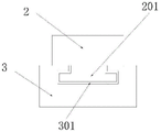
FIG. 3 is a schematic top view illustrating a connection structure between a fixing plate and a supporting plate according to an embodiment of the present disclosure;
FIG. 4 is a schematic structural view of a threaded post and a moving block according to an embodiment of the present application;
FIG. 5 is a schematic view of a right side connection structure of an adjustment plate according to an embodiment of the present application;
fig. 6 is a schematic view of a connection structure of a right side of a viewing plate and a rotating plate according to an embodiment of the present application.
In the figure: 1. a placing seat; 2. a support plate; 201. a slider; 3. a fixing plate; 301. a moving groove; 4. a base; 5. a hydraulic cylinder; 6. a gooseneck; 7. an illuminating lamp; 8. a rotating plate; 9. a rotating shaft; 10. a reading board; 11. a connecting seat; 12. a servo motor; 13. a threaded post; 14. a moving block; 15. a support frame; 16. an electric push rod; 17. pressing a plate; 18. an auxiliary plate; 19. a first rotating frame; 20. an adjusting plate; 21. and a second rotating frame.
Detailed Description
In order to make the technical solutions better understood by those skilled in the art, the technical solutions in the embodiments of the present application will be clearly and completely described below with reference to the drawings in the embodiments of the present application, and it is obvious that the described embodiments are only partial embodiments of the present application, but not all embodiments. All other embodiments, which can be derived by a person skilled in the art from the embodiments given herein without making any creative effort, shall fall within the protection scope of the present application.
It should be noted that the terms "first," "second," and the like in the description and claims of this application and in the drawings described above are used for distinguishing between similar elements and not necessarily for describing a particular sequential or chronological order. It should be understood that the data so used may be interchanged under appropriate circumstances such that embodiments of the application described herein may be used. Furthermore, the terms "comprises," "comprising," and "having," and any variations thereof, are intended to cover a non-exclusive inclusion, such that a process, method, system, article, or apparatus that comprises a list of steps or elements is not necessarily limited to those steps or elements expressly listed, but may include other steps or elements not expressly listed or inherent to such process, method, article, or apparatus.
In this application, the terms "upper", "lower", "left", "right", "front", "rear", "top", "bottom", "inner", "outer", "middle", "vertical", "horizontal", "lateral", "longitudinal", and the like indicate orientations or positional relationships based on the orientations or positional relationships shown in the drawings. These terms are used primarily to better describe the present application and its embodiments, and are not used to limit the indicated devices, elements or components to a particular orientation or to be constructed and operated in a particular orientation.
Moreover, some of the above terms may be used to indicate other meanings besides the orientation or positional relationship, for example, the term "on" may also be used to indicate some kind of attachment or connection relationship in some cases. The specific meaning of these terms in this application will be understood by those of ordinary skill in the art as appropriate.
Furthermore, the terms "mounted," "disposed," "provided," "connected," and "sleeved" are to be construed broadly. For example, it may be a fixed connection, a removable connection, or a unitary construction; can be a mechanical connection, or an electrical connection; may be directly connected, or indirectly connected through intervening media, or may be in internal communication between two devices, elements or components. The specific meaning of the above terms in the present application can be understood by those of ordinary skill in the art as appropriate.
It should be noted that the embodiments and features of the embodiments in the present application may be combined with each other without conflict. The present application will be described in detail below with reference to the embodiments with reference to the attached drawings.
The auxiliary viewing device of the present embodiment can be applied to various servo motors, for example, the following servo motor having a good dustproof effect is provided in the present embodiment, and the auxiliary viewing device of the present embodiment can be used to place the following servo motor.
A servo motor with good dustproof effect comprises a machine body, wherein a radiating groove is formed in the machine body, a rear end cover is fixedly connected to one side of the machine body, a power supply connector is fixedly connected to one side of the rear end cover, a feedback connector is fixedly connected to one side, close to the power supply connector, of the rear end cover, a front end cover is fixedly connected to one side, far away from the rear end cover, of the machine body, a through hole is formed in the front end cover, a bearing cover fixing block is fixedly connected to one side, far away from the machine body, of the front end cover, a bearing cover is fixedly connected to the inside of the bearing cover fixing block, a clamping groove is formed in the bearing cover, a sealing cover is movably connected to the bearing cover through the clamping groove, a clamping block is fixedly connected to the sealing cover, an output shaft is arranged inside of the machine body, a flat key is fixedly connected to one side, far away from the machine body, of the output shaft, and an embedded block is fixedly connected to one side of the sealing cover, one side of the embedded block, which is far away from the sealing cover, is fixedly connected with a brush head.
Optionally, the shape and size of the clamping groove are matched with the shape and size of the clamping block, the clamping block is movably connected inside the clamping groove, and the sealing cover is movably connected with the bearing cover through the clamping groove and the clamping block.
Optionally, the sealing cover is in a fan shape, the included angle of the fan shape of the sealing cover is ninety degrees, and the maximum diameter of the sealing cover is larger than that of the bearing cover fixing block.
Optionally, the brush head is made of a fiber material, the brush head is made of an ultra-fine polymer fiber material, and the fixture block is a magnet.
Optionally, a gap exists between the output shaft and the bearing cover, the width of the embedded block is the same as that of the gap, and the width of the brush head is the same as that of the gap.
Optionally, the depth of the clamping groove is smaller than the thickness of the bearing cover, and the thickness of the sealing cover is smaller than the thickness of the bearing cover.
Optionally, the shape and size of the rear end cover are matched with the shape and size of the machine body, the number of the through holes is four, and the four through holes are circumferentially arrayed on the front end cover.
Optionally, the number of the clamping grooves is a plurality, the clamping grooves are circumferentially arrayed on one side, away from the machine body, of the bearing cover, two clamping blocks are arranged on the sealing cover, and the distribution positions of the clamping blocks are matched with the distribution positions of the clamping grooves.
Of course, the present embodiment can also be used for placing servo motors with other structures. Here, a description is not repeated, and the following describes an auxiliary viewing apparatus according to an embodiment of the present application.
Referring to fig. 1-6, an auxiliary reading device for literature research and repair includes a placing seat 1, a rotating plate 8, a rotating shaft 9, a reading plate 10, a height adjusting mechanism, an angle adjusting mechanism and a clamping mechanism; the top surface of the placing seat 1 is fixedly connected with a rotating plate 8, the side surface of the rotating plate 8 is fixedly connected with a rotating shaft 9, and the surface of the rotating shaft 9 is sleeved with a reading board 10;
the height adjusting mechanism comprises a supporting plate 2, a fixing plate 3, a base 4 and a hydraulic cylinder 5, wherein the supporting plate 2 is fixedly connected to the bottom side surface of the placing seat 1, the fixing plate 3 is attached to the side surface of the supporting plate 2, the base 4 is fixedly connected to the bottom side surface of the fixing plate 3, the hydraulic cylinder 5 is fixedly connected to the top side surface of the base 4, and the output end of the hydraulic cylinder 5 is fixedly connected to the bottom side surface of the supporting plate 2.
The number of the supporting plates 2 is four, and the four supporting plates 2 are positioned at four corner positions of the bottom surface of the placing seat 1, so that the placing seat 1 can be stably supported by the supporting plates 2; a moving groove 301 is formed in the side surface of the fixed plate 3, a sliding block 201 is connected to the inner cavity of the moving groove 301 in a sliding mode, the top cross section of the sliding block 201 and the moving groove 301 is of a T-shaped structure, and the sliding block 201 is fixedly connected with the side surface of the bottom end of the supporting plate 2 so that the supporting plate 2 can move conveniently; a gooseneck 6 is fixedly connected to the top side of the left end of the placing seat 1, and an illuminating lamp 7 is fixedly connected to the top end of the gooseneck 6, so that illumination is facilitated; the angle adjusting mechanism comprises a connecting seat 11, a servo motor 12, a threaded column 13, a moving block 14, a first rotating frame 19, a second rotating frame 21 and an adjusting plate 20, the connecting seat 11 is fixedly connected to the surface of the top side of the placing seat 1, the servo motor 12 is fixedly installed on the side surface of the connecting seat 11, the output end of the servo motor 12 is connected with the threaded column 13, the moving block 14 is sleeved on the surface of the threaded column 13 in a threaded manner, the first rotating frame 19 is fixedly connected to the surface of the top side of the moving block 14, the top side of the first rotating frame 19 is rotatably connected with the second rotating frame 21 through the adjusting plate 20, and the second rotating frame 21 is fixedly connected with the surface of the bottom side of the reading plate 10, so that the angle of the reading plate 10 can be adjusted conveniently; the number of the threaded columns 13 is two, and the two threaded columns 13 are arranged in parallel, so that the threaded columns 13 can be conveniently used; a first rotating groove is formed in the top surface of the first rotating frame 19, a first rotating shaft is fixedly connected to the inner wall of the first rotating groove, one end of an adjusting plate 20 is sleeved on the surface of the first rotating shaft, a second rotating groove is formed in the bottom surface of the second rotating frame 21, a second rotating shaft is fixedly connected to the inner wall of the second rotating groove, and the other end of the adjusting plate 20 is sleeved on the surface of the second rotating shaft, so that the adjusting plate 20 can rotate conveniently; the clamping mechanism comprises a supporting frame 15, an electric push rod 16, a pressing plate 17 and an auxiliary plate 18, wherein the supporting frame 15 is fixedly connected to the side surface of the reading plate 10, the electric push rod 16 is fixedly connected to the top surface of the reading plate 10, the pressing plate 17 is fixedly connected to the output end of the electric push rod 16, and the auxiliary plate 18 is fixedly connected to the side surface of the pressing plate 17, so that the operation is convenient; the number of the pressing plates 17 is two, the two pressing plates 17 are arranged in parallel, and the pressing plates 17 are fixedly connected through the auxiliary plate 18, so that the pressing plates 17 can be conveniently used.
When the utility model is used, electrical components appearing in the application are externally connected with a power supply and a control switch when in use, a hydraulic cylinder 5 is started, the hydraulic cylinder 5 pushes a fixedly connected support plate 2 to move, the support plate 2 drives a fixedly connected slide block 201 to move along a moving groove 301, the support plate 2 pushes a fixedly connected placing seat 1 to perform height adjustment, so that users with different height requirements can conveniently read and use, meanwhile, a servo motor 12 is started, the servo motor 12 drives a threaded column 13 to rotate, the threaded column 13 drives a surface threaded sleeve connection moving block 14 to move, the moving block 14 moves a first rotating frame 19, the first rotating frame 19 pushes a rotatably connected adjusting plate 20 to adjust the height of a second rotating frame 21, the second rotating frame 21 pushes a reading plate 10 to rotate, the reading plate 10 rotates around the surface of a rotating shaft 9, so that the reading plate 10 can conveniently perform angle adjustment, and the reading plate 10 can conveniently perform angle adjustment, meanwhile, the electric push rod 16 is started, the electric push rod 16 pushes the fixedly connected pressing plate 17 to move, the pressing plate 17 further clamps the read data, the storage stability of the read data is improved, and the use requirements of workers are met.
The application has the advantages that:
1. this kind of literature is studied and repaired with supplementary reading device novel in design, simple structure, under the effect of the mechanism of increaseing through setting up, be convenient for carry out the altitude mixture control to placing seat 1 through pneumatic cylinder 5 drive backup pad 2, satisfy the user of different height demands and read the use, the operation of being convenient for.
2. When the angle adjusting device is used, the inclination angle of the reading board 10 can be conveniently adjusted under the action of the arranged angle adjusting mechanism, the reading board 10 after being adjusted can be conveniently and stably placed, the placing stability of the reading board 10 is improved, the use requirement of workers is met, and the operation is convenient.
3. When the reading device is used, under the action of the arranged clamping mechanism, the electric push rod 16 can push the pressing plate 17 to stably clamp the read data on the surface of the reading plate 10, so that the stable storage of the read data is improved, a user can conveniently read the data, the practical value is high, and the reading device is suitable for popularization and use.
It is well within the skill of those in the art to implement, without undue experimentation, the present application is not directed to software and process improvements, as they relate to circuits and electronic components and modules.
The above description is only a preferred embodiment of the present application and is not intended to limit the present application, and various modifications and changes may be made by those skilled in the art. Any modification, equivalent replacement, improvement and the like made within the spirit and principle of the present application shall be included in the protection scope of the present application.
Claims (10)
1. The utility model provides a literature is studied and repaiied with supplementary reading device which characterized in that: comprises a placing seat (1), a rotating plate (8), a rotating shaft (9), a reading plate (10), a heightening mechanism, an angle adjusting mechanism and a clamping mechanism; wherein the surface of the top side of the placing seat (1) is fixedly connected with a rotating plate (8), the side surface of the rotating plate (8) is fixedly connected with a rotating shaft (9), and the surface of the rotating shaft (9) is sleeved with a reading board (10);
heightening mechanism includes backup pad (2), fixed plate (3), base (4) and pneumatic cylinder (5), backup pad (2) fixed connection is placing seat (1) bottom side surface, backup pad (2) side surface laminating has fixed plate (3), fixed plate (3) bottom side fixed surface is connected with base (4), base (4) top side fixed surface is connected with pneumatic cylinder (5), pneumatic cylinder (5) output and backup pad (2) bottom side fixed surface are connected.
2. The reading aid for literature research and study according to claim 1, wherein: the number of the supporting plates (2) is four, and the four supporting plates (2) are positioned at four corner positions of the bottom side surface of the placing seat (1).
3. The reading aid for literature research and study according to claim 1, wherein: the side surface of the fixed plate (3) is provided with a moving groove (301), the inner cavity of the moving groove (301) is connected with a sliding block (201) in a sliding mode, the overlooking cross section of the sliding block (201) and the moving groove (301) is of a T-shaped structure, and the sliding block (201) is fixedly connected with the side surface of the bottom end of the supporting plate (2).
4. The reading aid for literature research and study according to claim 1, wherein: the placing seat is characterized in that a gooseneck (6) is fixedly connected to the top side of the left end of the placing seat (1), and an illuminating lamp (7) is fixedly connected to the top end of the gooseneck (6).
5. The reading aid for literature research and study according to claim 1, wherein: the angle adjusting mechanism comprises a connecting seat (11), a servo motor (12), a threaded column (13), a moving block (14), a first rotating frame (19), a second rotating frame (21) and an adjusting plate (20), wherein the connecting seat (11) is fixedly connected to the top surface of a placing seat (1), the servo motor (12) is fixedly mounted on the side surface of the connecting seat (11), the threaded column (13) is connected to the output end of the servo motor (12), the moving block (14) is sleeved on the surface of the threaded column (13), the first rotating frame (19) is fixedly connected to the top surface of the moving block (14), the first rotating frame (19) is rotatably connected with the second rotating frame (21) through the adjusting plate (20), and the second rotating frame (21) is fixedly connected with the bottom surface of a reading plate (10).
6. The reading aid for literature research and study according to claim 1, wherein: the number of the threaded columns (13) is two, and the two threaded columns (13) are arranged in parallel.
7. The reading aid for literature research and study according to claim 1, wherein: first swivelling chute has been seted up to first rotating frame (19) top side surface, first swivelling chute inner wall fixedly connected with first rotation axis, regulating plate (20) one end has been cup jointed on first rotation axis surface.
8. The reading aid for literature research and study according to claim 1, wherein: and a second rotating groove is formed in the bottom side surface of the second rotating frame (21), a second rotating shaft is fixedly connected to the inner wall of the second rotating groove, and the other end of the adjusting plate (20) is sleeved on the surface of the second rotating shaft.
9. The reading aid for literature research and study according to claim 1, wherein: the clamping mechanism comprises a supporting frame (15), an electric push rod (16), a pressing plate (17) and an auxiliary plate (18), wherein the supporting frame (15) is fixedly connected to the side surface of the reading plate (10), the electric push rod (16) is fixedly connected to the top side surface of the reading plate (10), the pressing plate (17) is fixedly connected to the output end of the electric push rod (16), and the auxiliary plate (18) is fixedly connected to the side surface of the pressing plate (17).
10. The reading aid for literature research and study according to claim 1, wherein: the number of the pressing plates (17) is two, the two pressing plates (17) are placed in parallel, and the pressing plates (17) are fixedly connected through an auxiliary plate (18).
Priority Applications (1)
| Application Number | Priority Date | Filing Date | Title |
|---|---|---|---|
| CN202111643041.9A CN114271601A (en) | 2021-12-29 | 2021-12-29 | Literature is studied and repaired with supplementary reading device |
Applications Claiming Priority (1)
| Application Number | Priority Date | Filing Date | Title |
|---|---|---|---|
| CN202111643041.9A CN114271601A (en) | 2021-12-29 | 2021-12-29 | Literature is studied and repaired with supplementary reading device |
Publications (1)
| Publication Number | Publication Date |
|---|---|
| CN114271601A true CN114271601A (en) | 2022-04-05 |
Family
ID=80878117
Family Applications (1)
| Application Number | Title | Priority Date | Filing Date |
|---|---|---|---|
| CN202111643041.9A Pending CN114271601A (en) | 2021-12-29 | 2021-12-29 | Literature is studied and repaired with supplementary reading device |
Country Status (1)
| Country | Link |
|---|---|
| CN (1) | CN114271601A (en) |
Citations (12)
| Publication number | Priority date | Publication date | Assignee | Title |
|---|---|---|---|---|
| CN108703536A (en) * | 2018-05-18 | 2018-10-26 | 曹会鹃 | A kind of dressing table with intelligence auxiliary cosmetic function |
| CN108783946A (en) * | 2018-06-28 | 2018-11-13 | 湖南城市学院 | A kind of vocational education teaching desk |
| CN209315143U (en) * | 2018-12-21 | 2019-08-30 | 曲阜师范大学 | A new type of library reading table |
| CN209807469U (en) * | 2019-03-20 | 2019-12-20 | 马义元 | Book end convenient to press from both sides tightly |
| CN111568040A (en) * | 2020-05-10 | 2020-08-25 | 王莹莹 | Desk convenient to read |
| CN211902139U (en) * | 2020-03-18 | 2020-11-10 | 胡小军 | Projector for dance teaching |
| CN213247496U (en) * | 2020-08-12 | 2021-05-25 | 江苏新尚家具制造有限公司 | Height-adjustable intelligent desk |
| CN213587856U (en) * | 2020-09-03 | 2021-07-02 | 董伟锋 | Drawing reading device for construction engineering management |
| CN213664211U (en) * | 2020-10-30 | 2021-07-13 | 淮北师范大学 | Landscape design is with multi-functional portable drawing device |
| CN214179547U (en) * | 2020-09-15 | 2021-09-14 | 湖州万顺奇艺家具有限公司 | Desk convenient to remove and place |
| CN214580091U (en) * | 2020-05-22 | 2021-11-02 | 黎健敏 | Analogue means that municipal pipeline engineering planning was used |
| CN215125386U (en) * | 2021-03-03 | 2021-12-14 | 陕西理工大学 | A Mechatronics Tilt Reading Table |
-
2021
- 2021-12-29 CN CN202111643041.9A patent/CN114271601A/en active Pending
Patent Citations (12)
| Publication number | Priority date | Publication date | Assignee | Title |
|---|---|---|---|---|
| CN108703536A (en) * | 2018-05-18 | 2018-10-26 | 曹会鹃 | A kind of dressing table with intelligence auxiliary cosmetic function |
| CN108783946A (en) * | 2018-06-28 | 2018-11-13 | 湖南城市学院 | A kind of vocational education teaching desk |
| CN209315143U (en) * | 2018-12-21 | 2019-08-30 | 曲阜师范大学 | A new type of library reading table |
| CN209807469U (en) * | 2019-03-20 | 2019-12-20 | 马义元 | Book end convenient to press from both sides tightly |
| CN211902139U (en) * | 2020-03-18 | 2020-11-10 | 胡小军 | Projector for dance teaching |
| CN111568040A (en) * | 2020-05-10 | 2020-08-25 | 王莹莹 | Desk convenient to read |
| CN214580091U (en) * | 2020-05-22 | 2021-11-02 | 黎健敏 | Analogue means that municipal pipeline engineering planning was used |
| CN213247496U (en) * | 2020-08-12 | 2021-05-25 | 江苏新尚家具制造有限公司 | Height-adjustable intelligent desk |
| CN213587856U (en) * | 2020-09-03 | 2021-07-02 | 董伟锋 | Drawing reading device for construction engineering management |
| CN214179547U (en) * | 2020-09-15 | 2021-09-14 | 湖州万顺奇艺家具有限公司 | Desk convenient to remove and place |
| CN213664211U (en) * | 2020-10-30 | 2021-07-13 | 淮北师范大学 | Landscape design is with multi-functional portable drawing device |
| CN215125386U (en) * | 2021-03-03 | 2021-12-14 | 陕西理工大学 | A Mechatronics Tilt Reading Table |
Similar Documents
| Publication | Publication Date | Title |
|---|---|---|
| US8001674B2 (en) | Automatic disassembly machine | |
| CN210324644U (en) | Information management multimedia teaching device | |
| CN206115929U (en) | Ideological and political education publicity board | |
| CN216820226U (en) | Flexible printed circuit board cutting mechanism suitable for different specifications | |
| CN214414397U (en) | Indoor design drawing workstation | |
| CN213094030U (en) | Assembling device for amorphous silicon stator assembly of motor | |
| CN212995247U (en) | A drawing frame for architectural design | |
| CN213614054U (en) | Cylinder die for high-pressure casting | |
| CN222867173U (en) | Portable mosaic structure's fine arts teaching aid | |
| CN210875906U (en) | Support frame for spraying notebook computer shell | |
| CN223569040U (en) | Can be fast assembled manikin | |
| CN222600642U (en) | Three-dimensional magnetic field generating device | |
| CN221592231U (en) | A teaching auxiliary device for online education | |
| CN219843641U (en) | Mobile phone stabilizer suitable for mobile phone video fortune mirror | |
| CN221388612U (en) | Stamping platform of projector shell | |
| CN222085531U (en) | A height-adjustable animation work display device | |
| CN223522221U (en) | Building power equipment installation adjusting device | |
| CN209983731U (en) | Art design workstation | |
| CN213757175U (en) | Drawing device for advertisement design and manufacture | |
| CN216926404U (en) | Camera module pressure test equipment | |
| CN213673705U (en) | Fixing clamp for lettering equipment | |
| CN222397546U (en) | A modular partitioned filing cabinet | |
| CN217642187U (en) | Waterproof assembly based on electric appliance cabinet | |
| CN224224506U (en) | Efficient bending and forming device for extra-thick acrylic plate | |
| CN222094991U (en) | Laser marking machine with adjusting structure |
Legal Events
| Date | Code | Title | Description |
|---|---|---|---|
| PB01 | Publication | ||
| PB01 | Publication | ||
| SE01 | Entry into force of request for substantive examination | ||
| SE01 | Entry into force of request for substantive examination | ||
| RJ01 | Rejection of invention patent application after publication | ||
| RJ01 | Rejection of invention patent application after publication |
Application publication date: 20220405 |