CN114261878A - Lifting hook assembly with automatic adjusting mechanism for hoisting machinery - Google Patents
Lifting hook assembly with automatic adjusting mechanism for hoisting machinery Download PDFInfo
- Publication number
- CN114261878A CN114261878A CN202210002629.4A CN202210002629A CN114261878A CN 114261878 A CN114261878 A CN 114261878A CN 202210002629 A CN202210002629 A CN 202210002629A CN 114261878 A CN114261878 A CN 114261878A
- Authority
- CN
- China
- Prior art keywords
- fixedly connected
- screw rod
- frame
- groove
- reciprocating screw
- Prior art date
- Legal status (The legal status is an assumption and is not a legal conclusion. Google has not performed a legal analysis and makes no representation as to the accuracy of the status listed.)
- Withdrawn
Links
- 230000007246 mechanism Effects 0.000 title claims abstract description 37
- 238000013016 damping Methods 0.000 claims description 32
- 230000035939 shock Effects 0.000 claims description 17
- 230000001681 protective effect Effects 0.000 claims description 7
- 230000005389 magnetism Effects 0.000 claims description 5
- 238000007789 sealing Methods 0.000 claims description 3
- 238000000926 separation method Methods 0.000 claims description 3
- 238000000034 method Methods 0.000 description 21
- 229910000831 Steel Inorganic materials 0.000 description 8
- 239000010959 steel Substances 0.000 description 8
- 239000000463 material Substances 0.000 description 6
- 230000000694 effects Effects 0.000 description 4
- 238000006073 displacement reaction Methods 0.000 description 3
- 238000005299 abrasion Methods 0.000 description 2
- 230000006978 adaptation Effects 0.000 description 2
- 238000010030 laminating Methods 0.000 description 2
- 241000220317 Rosa Species 0.000 description 1
- 230000003044 adaptive effect Effects 0.000 description 1
- 230000009286 beneficial effect Effects 0.000 description 1
- 239000002360 explosive Substances 0.000 description 1
- 239000012943 hotmelt Substances 0.000 description 1
- 238000009776 industrial production Methods 0.000 description 1
- 230000001788 irregular Effects 0.000 description 1
- 239000002245 particle Substances 0.000 description 1
- 230000000630 rising effect Effects 0.000 description 1
Images



Landscapes
- Load-Engaging Elements For Cranes (AREA)
Abstract
The invention relates to the technical field of lifting hooks of hoisting machinery, in particular to a lifting hook assembly with an automatic adjusting mechanism and a first adjusting groove for the hoisting machinery, wherein a second adjusting groove is formed in the other side of the top of a lifting frame, a first reciprocating screw rod is arranged in the first adjusting groove, a second reciprocating screw rod is arranged in the second adjusting groove, a first driving motor is arranged at one end of the first reciprocating screw rod, and a second driving motor is arranged at one end of the second reciprocating screw rod. According to the invention, through the arrangement of the undercarriage, the first adjusting groove, the second adjusting groove, the first reciprocating screw rod, the second reciprocating screw rod, the first driving motor and the second driving motor, the whole equipment can be quickly and stably adjusted when in use.
Description
Technical Field
The invention relates to the technical field of lifting hooks of hoisting machinery, in particular to a lifting hook assembly with an automatic adjusting mechanism for the hoisting machinery.
Background
The crane is a mechanical device which is lifted and lowered or lifted and moved by a lifting hook or other lifting appliances in an intermittent and repeated working mode, is indispensable equipment for modern industrial production, and is widely applied to the operations of lifting, transporting, loading and unloading various materials, installing objects and the like. The hoisting machinery often has the characteristics of large load range, high operation strength, many varieties of hoisted weights, irregular shapes, intermittent work and the like, the states of the hoisted weights comprise different shapes such as sizes, lengths, particles and the like, and varieties such as hot-melt states, flammable and explosive dangerous objects and the like, and when the hoisting machinery carries materials and hoists operation, the hoisting machinery sometimes needs to move in different directions to operate simultaneously, the operation environment is variable, the hoisting process is complex, the technical difficulty is higher, and the risk factors are more. Therefore, the hoisting machinery selects a proper working mechanism and uses a proper lifting appliance device, the labor intensity of operators can be reduced, the working efficiency and the precision are improved, the falling of a lifted object and the damage of the lifted object are prevented, and the operation safety of the operators and the hoisting machinery is effectively guaranteed.
The hoisting mechanism, the running mechanism, the luffing mechanism and the rotating mechanism of the hoisting machine are generally called four major mechanisms for hoisting operation. The hoisting mechanism is a mechanism for realizing vertical lifting of materials, is an indispensable part of any crane, and is the most main and basic mechanism of the crane. The running mechanism is a mechanism for realizing horizontal movement and material handling through the running of a large crane trolley and a lifting appliance, and has the characteristics of trackless running and rail running. The luffing mechanism is a special working mechanism of the jib crane, and the luffing mechanism changes the operation amplitude and the hoisting operation by changing the length and the elevation angle of the jib. The rotating mechanism rotates around the vertical axis of the crane through the arm support to convey materials in the annular space. The hoisting machine realizes material handling and hoisting in place by the single movement of one mechanism or the combined movement of multiple mechanisms, wherein a lifting hook serving as a main form of a lifting appliance and a lifting rope are indispensable to the operation exerted in the operation process.
At present, the hoist is at the in-service use in-process, because there is not better adjusting device between lifting hook and the lifting rope, leads to the unable automatic adjustment of the hookup location that rises and falls of lifting rope, and the pulling force that the lifting hook rose and falls can not remain at the optimum position all the time, and the lifting hook can't realize with operating device's stable adaptation operation, influences the stability and the operation accuracy nature of hoisting machinery at the handling in-process. In severe cases, the position of the hoisted heavy object may shift, get unhooked or even overturn, which affects the working efficiency and safety of the operation.
Disclosure of Invention
The invention aims to provide a lifting hook assembly with an automatic adjusting mechanism for a lifting machine, and aims to solve the problems that the lifting connection position of a lifting rope cannot be automatically adjusted, the lifting tension of the lifting hook cannot be always kept at the optimal position, the lifting hook cannot realize stable adaptive operation with a working mechanism, the stability and the operation accuracy of the lifting machine in the lifting process are influenced, and the daily lifting operation efficiency and the use safety are not facilitated in the conventional lifting machine provided in the background art because a better adjusting device is not arranged between the lifting hook and the lifting rope.
In order to achieve the purpose, the invention provides the following technical scheme: a hook assembly with an automatic adjustment mechanism for a lifting machine, comprising:
the lifting frame comprises a lifting frame, wherein a first adjusting groove is formed in one side of the top of the lifting frame, a second adjusting groove is formed in the other side of the top of the lifting frame, a first reciprocating screw rod is arranged in the first adjusting groove, a second reciprocating screw rod is arranged in the second adjusting groove, a first driving motor is arranged at one end of the first reciprocating screw rod, a second driving motor is arranged at one end of the second reciprocating screw rod, a first bearing seat is arranged at the other side of the first reciprocating screw rod, a second bearing seat is arranged at the other end of the second reciprocating screw rod, a first rotating sleeve is arranged on the surface of the first reciprocating screw rod, a second rotating groove is arranged on the surface of the second reciprocating screw rod, a movable ring is arranged on the outer surface of the first rotating sleeve, an outer sleeve shaft is arranged on the outer surface of the movable ring, and a binding frame is fixedly connected to the top of the outer sleeve shaft, the surface of the binding frame is provided with a binding groove, and the inner wall of the binding groove is uniformly and fixedly connected with a separation binding ring;
the undercarriage, the inside fixedly connected with control frame of undercarriage, the top of control frame is provided with control panel, control panel's output passes through wire and first driving motor's input electric connection, control panel's output passes through wire and second driving motor's input electric connection, the one end swing joint of control frame has the damping pivot, one side of control frame has the apron through damping pivot swing joint, the fixed surface of apron is connected with the sealing washer, the surface of apron is provided with first magnetism and inhales the circle, the surface of control frame is provided with the second magnetism and inhales the circle, the joint groove has been seted up to one side of control frame.
Preferably, the inside in joint groove has connected gradually first fixture block and second fixture block from a left side to the right side, the first shock attenuation board of one side fixedly connected with of first fixture block, the second shock attenuation board of one side fixedly connected with of second fixture block, the inside of first shock attenuation board and second shock attenuation board evenly is provided with damping spring.
Preferably, the bottom of the undercarriage is fixedly connected with an underframe, the bottom of the underframe is provided with a movable groove, and the inside of the movable groove is movably connected with a rotating seat.
Preferably, a shaft rod is arranged inside the rotating seat, and one end of the shaft rod is fixedly connected with a limiting head.
Preferably, the bottom of the rotating seat is fixedly connected with a connecting block, and the bottom of the connecting block is fixedly connected with a lifting hook body.
Preferably, the inner surface of the rotating seat is provided with a first damping ring, and the outer surface of the rotating seat is provided with a second damping ring.
Preferably, both ends of the undercarriage are provided with movable shafts, and the surfaces of the movable shafts are provided with telescopic rods.
Preferably, the top end of the telescopic rod is fixedly connected with a wire fixing frame, and a wire fixing clamping ring is arranged on the surface of the wire fixing frame.
Preferably, one side of the inner wall of the undercarriage is fixedly connected with a first limiting frame, the other side of the inner wall of the undercarriage is fixedly connected with a second limiting frame, and the inner walls of the first limiting frame and the second limiting frame are provided with protective soft rubber pads.
Preferably, the two ends of the bottom of the undercarriage are fixedly connected with supporting bottom plates, and supporting foot seats are arranged at the bottoms of the supporting bottom plates.
Compared with the prior art, the invention has the beneficial effects that:
1. the lifting hook component with the automatic adjusting mechanism for the hoisting machinery can be used for quickly and stably adjusting and operating the whole equipment when in use through the arranged undercarriage, the first adjusting groove, the second adjusting groove, the first reciprocating screw rod, the second reciprocating screw rod, the first driving motor, the second driving motor, the first bearing seat, the second bearing seat, the first rotating sleeve, the second rotating groove, the movable ring, the outer sleeve shaft and the binding frame, in the actual use process, a worker firstly installs a lifting steel wire rope of the hoisting machinery in the binding groove of the binding frame, and stably binds the lifting steel wire rope through the separated binding ring in the binding groove to avoid the abrasion phenomenon, at the moment, the control operation of the first driving motor and the second driving motor in the control frame can be carried out through a control panel at the top of the control frame to respectively drive the first reciprocating screw rod or the second reciprocating screw rod to rotate, first reciprocal lead screw and the reciprocal lead screw rotation in-process of second, the first cover and the second rotation groove of rotating on its surface carry out the displacement operation respectively, drive the quick regulation of wire rope that rises and falls, first rotation cover is in the removal in-process, the binding frame of activity ring surface can keep the binding frame in the state of erectting all the time, improve holistic stability, when treating that first rotation cover and second rotation groove remove to the position with hoisting machinery looks adaptation, the lifting hook body through the chassis bottom connects the hoist and mount operation this moment, the lifting hook body is along with the undercarriage in-process that rises and falls, can remain stable vertical state all the time under the effect of axostylus axostyle and rotation seat, the first damping circle and the stable laminating of axostylus axostyle of activity inslot portion, the laminating of second damping circle and activity inslot portion simultaneously, improve holistic hoist and mount stability, the practicality of equipment design has been embodied.
2. The lifting hook component with the automatic adjusting mechanism for the lifting machinery further improves the adjustment stability of the whole equipment through a control frame, a clamping groove, a first clamping block, a second clamping block, a first damping plate, a second damping plate, a damping spring, a movable shaft, a telescopic rod, a wire fixing frame, a wire fixing clamping ring, a supporting bottom plate and a supporting foot seat, the whole equipment can stably support the ground through the supporting bottom plate and the supporting foot seat at the bottom in the daily use process, at the moment, in the adjusting process of a first driving motor and a second driving motor in the lifting gear, a first limiting frame and a second limiting frame on two sides of the inner wall of the lifting gear can stably limit the adjusted first rotating sleeve and the second rotating groove through a protective soft rubber pad on the inner wall, and simultaneously ensures that the adjusted first rotating sleeve and the adjusted second rotating groove can be always in a stable state, the stability of hoist and mount in-process is improved, the telescopic link at undercarriage both ends can carry out quick rotation operation through the loose axle simultaneously, and the solidus frame of its one end is played the stable circle of the holistic wire rope that rises and falls of hoist and mount undercarriage through first spacing, and the telescopic link can carry out stable length adjustment operation simultaneously, and then realizes the stable spacing operation to the wire rope that rises and falls, improves the stability of the whole hoist and mount process that carries out greatly, has embodied equipment design's comprehensiveness.
Drawings
FIG. 1 is a perspective view of the structure of the present invention;
FIG. 2 is a schematic view of the first and second reciprocating screw configurations of the present invention in a separated view;
FIG. 3 is a schematic view of the first and second spacing structures of the present invention;
FIG. 4 is a general schematic view of the hook body structure of the present invention;
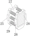
FIG. 5 is a schematic view of the first and second damping plates of the present invention in a perspective view;
FIG. 6 is an enlarged view of the structure at A in FIG. 1 according to the present invention.
In the figure: 1. a landing gear; 2. a first adjustment groove; 3. a second adjustment groove; 4. a first reciprocating screw rod; 5. a second reciprocating screw rod; 6. a first drive motor; 7. a second drive motor; 8. a first bearing housing; 9. a second bearing housing; 10. a first rotating sleeve; 11. a second rotating groove; 12. a movable ring; 13. an outer sleeve shaft; 14. a binding frame; 15. binding the fixing groove; 16. separating the binding rings; 17. a control frame; 18. a control panel; 19. a damping rotating shaft; 20. a cover plate; 21. a seal ring; 22. a first magnetic attraction ring; 23. a second magnetic attraction ring; 24. a clamping groove; 25. a first clamping block; 26. a second fixture block; 27. a first damper plate; 28. a second damper plate; 29. a damping spring; 30. a chassis; 31. a movable groove; 32. a rotating seat; 33. a shaft lever; 34. a limiting head; 35. connecting blocks; 36. a hook body; 37. a first damping ring; 38. a second damping ring; 39. a movable shaft; 40. a telescopic rod; 41. a wire fixing frame; 42. a wire fixing snap ring; 43. a first limit bracket; 44. a second limiting frame; 45. a protective soft rubber cushion; 46. a support base plate; 47. a supporting foot seat.
Detailed Description
The technical solutions in the embodiments of the present invention will be clearly and completely described below with reference to the drawings in the embodiments of the present invention, and it is obvious that the described embodiments are only a part of the embodiments of the present invention, and not all of the embodiments. All other embodiments, which can be derived by a person skilled in the art from the embodiments given herein without making any creative effort, shall fall within the protection scope of the present invention.
Referring to fig. 1-6, an embodiment of the present invention is shown:
the utility model provides a lifting hook subassembly that has automatic guiding mechanism for hoisting machinery, the first reciprocal lead screw 4, the reciprocal lead screw 5 of second, first driving motor 6, second driving motor 7, first bearing frame 8, second bearing frame 9, control panel 18, damping pivot 19, first magnetism suction ring 22, second magnetism suction ring 23, damping spring 29, loose axle 39, telescopic link 40 and protection soft cushion 45 that use in this application are the product that can directly purchase on the market, and its principle and connected mode are the prior art that technical personnel in this field are familiar, include:
a first adjusting groove 2 is formed in one side of the top of the undercarriage 1, a second adjusting groove 3 is formed in the other side of the top of the undercarriage 1, a first reciprocating screw rod 4 is arranged in the first adjusting groove 2, a second reciprocating screw rod 5 is arranged in the second adjusting groove 3, a first driving motor 6 is arranged at one end of the first reciprocating screw rod 4, a second driving motor 7 is arranged at one end of the second reciprocating screw rod 5, a first bearing seat 8 is arranged on the other side of the first reciprocating screw rod 4, a second bearing seat 9 is arranged at the other end of the second reciprocating screw rod 5, a first rotating sleeve 10 is arranged on the surface of the first reciprocating screw rod 4, a second rotating groove 11 is arranged on the surface of the second reciprocating screw rod 5, a movable ring 12 is arranged on the outer surface of the first rotating sleeve 10, an outer sleeve shaft 13 is arranged on the outer surface of the movable ring 12, and a binding frame 14 is fixedly connected to the top of the outer sleeve shaft 13, the surface of the binding frame 14 is provided with a binding groove 15, the inner wall of the binding groove 15 is uniformly and fixedly connected with a separation binding ring 16, the bottom of the undercarriage 1 is fixedly connected with an underframe 30, the bottom of the underframe 30 is provided with a movable groove 31, the interior of the movable groove 31 is movably connected with a rotating seat 32, the interior of the rotating seat 32 is provided with a shaft rod 33, one end of the shaft rod 33 is fixedly connected with a limiting head 34, the bottom of the rotating seat 32 is fixedly connected with a connecting block 35, the bottom of the connecting block 35 is fixedly connected with a lifting hook body 36, the inner surface of the rotating seat 32 is provided with a first damping ring 37, the outer surface of the rotating seat 32 is provided with a second damping ring 38, the two ends of the undercarriage 1 are respectively provided with a movable shaft 39, the surface of the movable shaft 39 is provided with a telescopic rod 40, the top end of the telescopic rod 40 is fixedly connected with a wire fixing frame 41, the surface of the wire fixing frame 41 is provided with a wire fixing clamping ring 42, one side of the inner wall of the undercarriage 1 is fixedly connected with a first limiting frame 43, the other side of the inner wall of the landing gear 1 is fixedly connected with a second limiting frame 44, the inner walls of the first limiting frame 43 and the second limiting frame 44 are provided with a protective soft rubber cushion 45, two ends of the bottom of the landing gear 1 are fixedly connected with supporting bottom plates 46, the bottom of the supporting bottom plate 46 is provided with a supporting foot seat 47, the first driving motor 6 and the second driving motor 7 are controlled to operate so as to respectively drive the first reciprocating screw rod 4 or the second reciprocating screw rod 5 to rotate, in the rotating process of the first reciprocating screw rod 4 and the second reciprocating screw rod 5, the first rotating sleeve 10 and the second rotating groove 11 on the surface of the first rotating sleeve 10 respectively carry out displacement operation so as to drive the steel wire rope to adjust rapidly, in the moving process of the first rotating sleeve 10, the binding frame 14 on the outer surface of the movable ring 12 can always keep the binding frame 14 in a vertical state, the integral stability is improved, the first limiting frame 43 and the second limiting frame 44 on two sides of the inner wall of the landing gear 1 can pass through the protective soft rubber cushion 45 on the inner wall, performing stable limiting operation on the adjusted first rotating sleeve 10 and the adjusted second rotating groove 11, and simultaneously ensuring that the adjusted first rotating sleeve 10 and the adjusted second rotating groove 11 can be always in a stable state;
a control frame 17, a control frame 17 is fixedly connected inside the landing gear 1, a control panel 18 is arranged on the top of the control frame 17, an output end of the control panel 18 is electrically connected with an input end of a first driving motor 6 through a lead, an output end of the control panel 18 is electrically connected with an input end of a second driving motor 7 through a lead, one end of the control frame 17 is movably connected with a damping rotating shaft 19, one side of the control frame 17 is movably connected with a cover plate 20 through the damping rotating shaft 19, the surface of the cover plate 20 is fixedly connected with a sealing ring 21, the surface of the cover plate 20 is provided with a first magnetic attraction ring 22, the surface of the control frame 17 is provided with a second magnetic attraction ring 23, one side of the control frame 17 is provided with a clamping groove 24, the inside of the clamping groove 24 is sequentially connected with a first clamping block 25 and a second clamping block 26 from left to right, one side of the first clamping block 25 is fixedly connected with a first damping plate 27, and one side of the second clamping block 26 is fixedly connected with a second damping plate 28, the inside of first shock attenuation board 27 and second shock attenuation board 28 evenly is provided with damping spring 29, damping spring 29 can carry out stable shock attenuation operation through first shock attenuation board 27 and second shock attenuation board 28 respectively first driving motor 6 and the second driving motor 7 of the inside of control frame 17, and the shock attenuation in-process, the first fixture block 25 and the second fixture block 26 of first shock attenuation board 27 and second shock attenuation board 28 both sides can carry out stable removal operation along joint groove 24, improve holistic shock attenuation stability, help the whole more stable completion hoist and mount operation of equipment.
The working principle is as follows: when in use, a user firstly installs the lifting steel wire rope of the hoisting machine in the binding groove 15 of the binding frame 14, and stably binds the lifting steel wire rope through the separating binding ring 16 in the binding groove 15 to avoid abrasion phenomena, at the moment, the control operation of the first driving motor 6 and the second driving motor 7 in the control frame 17 can be carried out through the control panel 18 at the top of the control frame 17 to respectively drive the first reciprocating screw rod 4 or the second reciprocating screw rod 5 to rotate, the first rotating sleeve 10 and the second rotating groove 11 on the surface of the first reciprocating screw rod 4 and the second reciprocating screw rod 5 respectively carry out displacement operation in the rotating process to drive the lifting steel wire rope to be rapidly adjusted, the binding frame 14 on the outer surface of the movable ring 12 can always keep the binding frame 14 in a vertical state in the moving process of the first rotating sleeve 10, and the integral stability is improved, when the first rotating sleeve 10 and the second rotating groove 11 move to the position matched with the hoisting machinery, the lifting operation is carried out through the hook body 36 at the bottom of the underframe 30, the hook body 36 can always keep a stable vertical state under the action of the shaft lever 33 and the rotating seat 32 in the rising and falling processes along with the undercarriage 1, the first damping ring 37 in the movable groove 31 is stably attached to the shaft lever 33, meanwhile, the second damping ring 38 is attached to the inside of the movable groove 31, the overall lifting stability is improved, in the daily use process, the whole equipment can stably support the ground through the supporting base plate 46 and the supporting foot seat 47 at the bottom, at the moment, the first driving motor 6 and the second driving motor 7 are adjusted in the undercarriage 1, the first limiting frame 43 and the second limiting frame 44 at two sides of the inner wall of the undercarriage 1 can pass through the protective soft rubber pad 45 at the inner wall, the stable limiting operation is performed on the adjusted first rotating sleeve 10 and the adjusted second rotating groove 11, and meanwhile, the adjusted first rotating sleeve 10 and the adjusted second rotating groove 11 can be always in a stable state, so that the stability in the hoisting process is improved, meanwhile, the telescopic rods 40 at two ends of the undercarriage 1 can perform rapid rotating operation through the movable shaft 39, the wire fixing frame 41 at one end stably encircles the whole lifting steel wire rope of the hoisting undercarriage 1 through the first limiting frame 43, and meanwhile, the telescopic rods 40 can perform stable length adjusting operation, so that the stable limiting operation on the lifting steel wire rope is realized.
It will be evident to those skilled in the art that the invention is not limited to the details of the foregoing illustrative embodiments, and that the present invention may be embodied in other specific forms without departing from the spirit or essential attributes thereof. The present embodiments are therefore to be considered in all respects as illustrative and not restrictive, the scope of the invention being indicated by the appended claims rather than by the foregoing description, and all changes which come within the meaning and range of equivalency of the claims are therefore intended to be embraced therein. Any reference sign in a claim should not be construed as limiting the claim concerned.
Claims (10)
1. A hook assembly with an automatic adjustment mechanism for a lifting machine, comprising:
the undercarriage (1), one side at the top of the undercarriage (1) is provided with a first adjusting groove (2), the other side at the top of the undercarriage (1) is provided with a second adjusting groove (3), a first reciprocating screw rod (4) is arranged in the first adjusting groove (2), a second reciprocating screw rod (5) is arranged in the second adjusting groove (3), one end of the first reciprocating screw rod (4) is provided with a first driving motor (6), one end of the second reciprocating screw rod (5) is provided with a second driving motor (7), the other side of the first reciprocating screw rod (4) is provided with a first bearing seat (8), the other end of the second reciprocating screw rod (5) is provided with a second bearing seat (9), the surface of the first reciprocating screw rod (4) is provided with a first rotating sleeve (10), the surface of the second reciprocating screw rod (5) is provided with a second rotating groove (11), a movable ring (12) is arranged on the outer surface of the first rotating sleeve (10), an outer sleeve shaft (13) is arranged on the outer surface of the movable ring (12), a binding frame (14) is fixedly connected to the top of the outer sleeve shaft (13), a binding groove (15) is formed in the surface of the binding frame (14), and a separation binding ring (16) is uniformly and fixedly connected to the inner wall of the binding groove (15);
a control frame (17), the interior of the undercarriage (1) is fixedly connected with the control frame (17), the top of the control frame (17) is provided with a control panel (18), the output end of the control panel (18) is electrically connected with the input end of the first driving motor (6) through a lead, the output end of the control panel (18) is electrically connected with the input end of the second driving motor (7) through a lead, one end of the control frame (17) is movably connected with a damping rotating shaft (19), one side of the control frame (17) is movably connected with a cover plate (20) through the damping rotating shaft (19), a sealing ring (21) is fixedly connected to the surface of the cover plate (20), a first magnetic attraction ring (22) is arranged on the surface of the cover plate (20), the surface of control frame (17) is provided with second magnetism and inhales circle (23), joint groove (24) have been seted up to one side of control frame (17).
2. The hook assembly with an automatic adjusting mechanism for a lifting machine of claim 1, wherein: the inside in joint groove (24) has connected gradually first fixture block (25) and second fixture block (26) from a left side to the right side, the first shock attenuation board (27) of one side fixedly connected with of first fixture block (25), one side fixedly connected with second shock attenuation board (28) of second fixture block (26), the inside of first shock attenuation board (27) and second shock attenuation board (28) evenly is provided with damping spring (29).
3. The hook assembly with an automatic adjusting mechanism for a lifting machine of claim 1, wherein: the bottom of the undercarriage (1) is fixedly connected with an underframe (30), a movable groove (31) is formed in the bottom of the underframe (30), and a rotating seat (32) is movably connected inside the movable groove (31).
4. The assembly of claim 3, wherein the hook assembly comprises an automatic adjustment mechanism, and wherein: a shaft rod (33) is arranged inside the rotating seat (32), and one end of the shaft rod (33) is fixedly connected with a limiting head (34).
5. The assembly of claim 3, wherein the hook assembly comprises an automatic adjustment mechanism, and wherein: the bottom fixedly connected with connecting block (35) of rotating seat (32), the bottom fixedly connected with lifting hook body (36) of connecting block (35).
6. The assembly of claim 3, wherein the hook assembly comprises an automatic adjustment mechanism, and wherein: the inner surface of the rotating seat (32) is provided with a first damping ring (37), and the outer surface of the rotating seat (32) is provided with a second damping ring (38).
7. The hook assembly with an automatic adjusting mechanism for a lifting machine of claim 1, wherein: both ends of undercarriage (1) all are provided with loose axle (39), the surface of loose axle (39) is provided with telescopic link (40).
8. The assembly of claim 7, wherein the hook assembly comprises an automatic adjustment mechanism, and wherein: the top end of the telescopic rod (40) is fixedly connected with a wire fixing frame (41), and a wire fixing clamping ring (42) is arranged on the surface of the wire fixing frame (41).
9. The hook assembly with an automatic adjusting mechanism for a lifting machine of claim 1, wherein: the landing gear is characterized in that a first limiting frame (43) is fixedly connected to one side of the inner wall of the landing gear (1), a second limiting frame (44) is fixedly connected to the other side of the inner wall of the landing gear (1), and protective soft rubber pads (45) are arranged on the inner walls of the first limiting frame (43) and the second limiting frame (44).
10. The hook assembly with an automatic adjusting mechanism for a lifting machine of claim 1, wherein: the landing gear is characterized in that two ends of the bottom of the landing gear (1) are fixedly connected with supporting bottom plates (46), and supporting foot seats (47) are arranged at the bottoms of the supporting bottom plates (46).
Priority Applications (1)
| Application Number | Priority Date | Filing Date | Title |
|---|---|---|---|
| CN202210002629.4A CN114261878A (en) | 2022-01-04 | 2022-01-04 | Lifting hook assembly with automatic adjusting mechanism for hoisting machinery |
Applications Claiming Priority (1)
| Application Number | Priority Date | Filing Date | Title |
|---|---|---|---|
| CN202210002629.4A CN114261878A (en) | 2022-01-04 | 2022-01-04 | Lifting hook assembly with automatic adjusting mechanism for hoisting machinery |
Publications (1)
| Publication Number | Publication Date |
|---|---|
| CN114261878A true CN114261878A (en) | 2022-04-01 |
Family
ID=80832333
Family Applications (1)
| Application Number | Title | Priority Date | Filing Date |
|---|---|---|---|
| CN202210002629.4A Withdrawn CN114261878A (en) | 2022-01-04 | 2022-01-04 | Lifting hook assembly with automatic adjusting mechanism for hoisting machinery |
Country Status (1)
| Country | Link |
|---|---|
| CN (1) | CN114261878A (en) |
Cited By (1)
| Publication number | Priority date | Publication date | Assignee | Title |
|---|---|---|---|---|
| CN115095165A (en) * | 2022-06-16 | 2022-09-23 | 浙江国进建设有限公司 | Installation device for high-altitude structure body in factory building construction |
-
2022
- 2022-01-04 CN CN202210002629.4A patent/CN114261878A/en not_active Withdrawn
Cited By (1)
| Publication number | Priority date | Publication date | Assignee | Title |
|---|---|---|---|---|
| CN115095165A (en) * | 2022-06-16 | 2022-09-23 | 浙江国进建设有限公司 | Installation device for high-altitude structure body in factory building construction |
Similar Documents
| Publication | Publication Date | Title |
|---|---|---|
| KR20220166686A (en) | Mobile type lifter | |
| CN109573828A (en) | Broad-adjustable all-around mobile formula portal frame | |
| CN209601918U (en) | A kind of suspender of adjustable angle | |
| CN214653149U (en) | Movable type hoisting operation vehicle | |
| CN209276037U (en) | A kind of Multifunctional hoisting device | |
| CN105347166B (en) | A kind of hanging apparatus | |
| RU144273U1 (en) | SELF-PROPELLED MULTIFUNCTIONAL MANIPULATOR | |
| CN213231167U (en) | Self-rotating crane sling | |
| CN219075728U (en) | Mechanical arm | |
| CN103253602B (en) | The elevated super lifting device of crawler vehicle voluntarily and hoisting crane | |
| CN202481909U (en) | Wire coil lifting device | |
| CN215946556U (en) | Automatic heavy object hoisting and carrying device | |
| CN201619967U (en) | Hoisting equipment | |
| CN207957600U (en) | A kind of novel metallurgical crane hoisting mechanism | |
| CN203624832U (en) | Grab bucket convenient to move | |
| CN212269185U (en) | Hoisting device with variable hoisting diameter | |
| CN218785942U (en) | Battery replacing equipment | |
| CN219469491U (en) | Anti-offset device of trolley | |
| CN104192736A (en) | Tower crane with variable triangular hoisting rope | |
| CN214933860U (en) | Automatic conveying device for counterweight box body | |
| CN108015751A (en) | One kind crawl lifting boosting manipulator | |
| CN211712452U (en) | A new type of tunnel gantry crane | |
| CN219603124U (en) | Hanging basket operation accessory integrated with hoisting mechanism | |
| CN208249739U (en) | A kind of horizontal injection press Microhoist | |
| CN115477248B (en) | A device for carrying heavy objects at high altitudes |
Legal Events
| Date | Code | Title | Description |
|---|---|---|---|
| PB01 | Publication | ||
| PB01 | Publication | ||
| SE01 | Entry into force of request for substantive examination | ||
| SE01 | Entry into force of request for substantive examination | ||
| WW01 | Invention patent application withdrawn after publication | ||
| WW01 | Invention patent application withdrawn after publication |
Application publication date: 20220401 |