CN114251062A - Novel automatic calandria system of rig - Google Patents
Novel automatic calandria system of rig Download PDFInfo
- Publication number
- CN114251062A CN114251062A CN202010998389.9A CN202010998389A CN114251062A CN 114251062 A CN114251062 A CN 114251062A CN 202010998389 A CN202010998389 A CN 202010998389A CN 114251062 A CN114251062 A CN 114251062A
- Authority
- CN
- China
- Prior art keywords
- pipe
- automatic pipe
- bridge crane
- platform
- pulley
- Prior art date
- Legal status (The legal status is an assumption and is not a legal conclusion. Google has not performed a legal analysis and makes no representation as to the accuracy of the status listed.)
- Pending
Links
- XEEYBQQBJWHFJM-UHFFFAOYSA-N Iron Chemical compound [Fe] XEEYBQQBJWHFJM-UHFFFAOYSA-N 0.000 claims abstract description 22
- 238000005553 drilling Methods 0.000 claims abstract description 19
- 210000000707 wrist Anatomy 0.000 claims abstract description 16
- 229910052742 iron Inorganic materials 0.000 claims abstract description 11
- 230000002146 bilateral effect Effects 0.000 claims abstract description 6
- 210000000078 claw Anatomy 0.000 claims description 13
- 230000007246 mechanism Effects 0.000 claims description 9
- 230000009471 action Effects 0.000 claims description 5
- 230000036544 posture Effects 0.000 claims description 5
- 238000013519 translation Methods 0.000 claims description 4
- 238000001514 detection method Methods 0.000 claims description 3
- 230000010354 integration Effects 0.000 claims description 3
- 238000000034 method Methods 0.000 description 5
- 230000008569 process Effects 0.000 description 3
- 230000009286 beneficial effect Effects 0.000 description 2
- 239000000969 carrier Substances 0.000 description 2
- 239000003638 chemical reducing agent Substances 0.000 description 2
- 238000010586 diagram Methods 0.000 description 2
- 229910000831 Steel Inorganic materials 0.000 description 1
- 238000013461 design Methods 0.000 description 1
- 238000007599 discharging Methods 0.000 description 1
- 230000000694 effects Effects 0.000 description 1
- 238000012423 maintenance Methods 0.000 description 1
- 238000012986 modification Methods 0.000 description 1
- 230000004048 modification Effects 0.000 description 1
- 238000005457 optimization Methods 0.000 description 1
- 238000012545 processing Methods 0.000 description 1
- 238000012827 research and development Methods 0.000 description 1
- 239000010959 steel Substances 0.000 description 1
- 230000001360 synchronised effect Effects 0.000 description 1
- XLYOFNOQVPJJNP-UHFFFAOYSA-N water Substances O XLYOFNOQVPJJNP-UHFFFAOYSA-N 0.000 description 1
Images





Classifications
-
- E—FIXED CONSTRUCTIONS
- E21—EARTH OR ROCK DRILLING; MINING
- E21B—EARTH OR ROCK DRILLING; OBTAINING OIL, GAS, WATER, SOLUBLE OR MELTABLE MATERIALS OR A SLURRY OF MINERALS FROM WELLS
- E21B19/00—Handling rods, casings, tubes or the like outside the borehole, e.g. in the derrick; Apparatus for feeding the rods or cables
- E21B19/14—Racks, ramps, troughs or bins, for holding the lengths of rod singly or connected; Handling between storage place and borehole
Landscapes
- Engineering & Computer Science (AREA)
- Life Sciences & Earth Sciences (AREA)
- Geology (AREA)
- Mining & Mineral Resources (AREA)
- Mechanical Engineering (AREA)
- Physics & Mathematics (AREA)
- Environmental & Geological Engineering (AREA)
- Fluid Mechanics (AREA)
- General Life Sciences & Earth Sciences (AREA)
- Geochemistry & Mineralogy (AREA)
- Earth Drilling (AREA)
Abstract
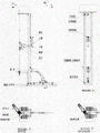
The invention discloses a novel automatic pipe arranging system of a drilling machine, which can be applied to an offshore drilling platform or a land drilling machine. The system comprises an automatic pipe grabbing machine, an iron roughneck, a bridge crane, a rat hole and an automatic pipe arrangement control system, and is positioned outside a derrick on the ground or above a large platform. The function of the device is to connect a single horizontal drill rod into three drill rods, and vertically arrange the three drill rods in a derrick stand box in sequence. The automatic pipe grabbing machine comprises a bilateral upright post slide rail support frame, a pulley, an upper arm, a lower arm, a rotary wrist and a gripper; the upper end of the double-side upright post sliding rail support frame is connected with a derrick racking platform, the lower end of the double-side upright post sliding rail support frame is fixedly connected with the ground or a large platform, and the hand grip can extend to the ground or the large platform to directly grip the pipe without a catwalk to convey the pipe. The pipe arranging work can be independently completed by matching the bridge crane with the automatic pipe grabbing machine, the tripping operation is not influenced, and the manual operation is not needed. The system greatly improves the safety of drilling operation, improves the production efficiency and reduces the labor cost.
Description
Technical Field
The present invention relates to a pipe handling system for use in marine or land oil drilling or exploration operations.
Background
The pipe arranging operation is that a single drill rod horizontally placed from a water inlet is rotated to be in a vertical state, then the drill rods are connected into three pipes and vertically arranged in a stand box to be taken when the drill rods are taken down, and the pipe arranging operation is an important link of the operation of the drilling and repairing machine. The calandria of traditional rig all is manual operation, and the derrick worker need stand and operate on the racking platform that is higher than the rig floor twenty several meters, and the danger coefficient is high, and operational environment is abominable, and automatic pipe processing system has certain research and development and application in recent years, but efficiency also needs to be promoted, and the scheme has the space of further optimization. The operation flow is that the automatic catwalk is used for sending the drill rods to the lower part of the elevator, then the elevator is used for lifting the drill rods, the rat hole is matched with an iron driller to connect the drill rods into three from a single one, then the drill floor mechanical arm is used for discharging the lower ends of the drill rods to be in place, and then the two-layer platform mechanical arm is used for holding the drill rods to enter the finger beam. The equipment that mutually supports is many, and the step is loaded down with trivial details, and is efficient.
As in chinese patent application No.: CN201910220582.7, inventive name: a full-hydraulic deep well drilling machine. The automatic pipe arrangement needs the cooperation of an automatic catwalk, an automatic pipe arrangement machine, an iron roughneck, a top drive and the like. The automatic catwalk machine realizes the conveying of drilling tools from the ground to the drill floor, the operation of connecting and detaching the stand roots needs top drive matching, independent pipe arrangement cannot be realized, the system is complex, and the operation efficiency is low.
As in chinese patent application No.: CN201320540562.6, inventive name: a novel automatic pipe grabbing manipulator. The manipulator is arranged below the second-layer platform, and is limited in that the finger beam structure can only move front and back and can not move left and right, so that the arm needs to be folded and can be long enough to cover all the stands in the rectangular finger beam, and if the stands need to be enlarged, the manipulator needs to be redesigned; and the pipe cannot be lifted without the lifting function, the drill rod row is required to be placed into the stand and is matched with a drill floor mechanical arm to be operated in two steps, and the efficiency is low.
The automatic pipe arranging system disclosed by the invention does not need manual operation, catwalks or top drives, can realize independent full-automatic off-line connection and disconnection operations, does not influence the starting and the drilling, reduces the required equipment, simplifies the operation steps, is suitable for the stands with different sizes, and does not need to modify the design even if the size of the stand box is increased.
Disclosure of Invention
The invention aims to realize the grabbing and rotating of the drill rods, the connection and the disconnection of three drill rods, the full-automatic operation of the pipe arrangement can be realized while the drill rods are arranged in the stand box, the pipe arrangement can be carried out independently, and the pipe arrangement work can be finished more efficiently and safely without depending on an elevator and a catwalk.
In order to realize the functions, the invention provides an automatic pipe arranging system, which comprises: the automatic pipe grabbing machine comprises an automatic pipe grabbing machine for grabbing and rotating a drill rod, an iron roughneck matched with the automatic pipe grabbing machine to be buckled and unbuckled, a bridge crane for pipe arrangement, a rat hole and an automatic pipe arrangement control system, wherein the system is arranged at the front side outside a derrick, the automatic pipe grabbing machine is arranged on the ground or above a large platform and extends upwards to be connected with a racking platform structure, the bridge crane is connected and fixed above the racking platform, the rat hole is fixed under a drilling platform, a temporary storage position is arranged on one side of the rat hole and used for storing two sections of drill rods in the three processes of disassembly and assembly, and the iron roughneck can move on the drilling platform independently and can move between rat hole mouths to be buckled and unbuckled of the drill rods.
The automatic pipe grabbing machine is completely arranged on the outer side of the derrick and consists of a bilateral upright post slide rail support frame, a pulley, an upper arm, a lower arm, a rotary wrist and a gripper; the upper end of the double-side upright post sliding rail support frame is connected with a derrick racking platform, the lower end of the double-side upright post sliding rail support frame is fixedly connected with the ground or a large platform, and the hand grip can extend to the ground or the large platform to directly grip the pipe without a catwalk to convey the pipe.
The automatic pipe grabbing machine is characterized in that a box-type wrist rotating structure is adopted between a lower arm and a gripper, the structure is hinged with the lower arm and connected with the gripper through a rotating shaft, and the gripper is driven by a hydraulic cylinder to realize wrist rotating action when the gripper vertically postures pipes, so that the pipes are moved to a temporary storage position through a rat hole.
The pulley of the automatic pipe grabbing machine slides up and down along the sliding ranges of the sliding rail support frames of the upright posts at the two sides to the ground or the large platform to the second-layer platform; the amplitude of the upper swing arm and the lower swing arm is 90 degrees; the amplitude of the left-right wrist turning can be adjusted according to the temporary storage position.
The automatic pipe grabbing machine has the beneficial effects that: the slide rail structure of the automatic pipe grabbing machine extends to the second-layer platform from the ground, so that the automatic pipe grabbing machine has an up-and-down lifting function with enough stroke, and the functions of grabbing pipes and lifting by an elevator are replaced, so that the system can complete independent pipe grabbing and arranging operation without the cooperation of the elevator, and the operation efficiency is improved; the automatic pipe grabbing machine can be lowered to the ground below a drill floor, and the upper arm and the lower arm are long enough to reach a single horizontal drill rod on the ground, so that the drill rod is conveyed to the position above the drill floor without a ramp structure, and the drill rod is axially conveyed to the position below an elevator without an automatic catwalk machine, ramp and automatic catwalk equipment are omitted, the arrangement of a drilling machine is simplified, the pipe arranging operation process is simplified, and the operation efficiency is further improved; the automatic pipe grabbing machine has the advantages that the horizontal plane wrist rotating function is added besides the longitudinal plane arm folding function, so that the automatic pipe grabbing machine has the function of moving a drill rod from a rat hole to a temporary storage position in the three connecting and disconnecting processes, other auxiliary equipment is not required to be added, and the arrangement of a drill floor is simplified;
the bridge crane is arranged above the finger beam of the second-layer platform, is fixed on a derrick and comprises a front slideway beam, a rear slideway beam, a left slideway beam and a right slideway beam which are hung on the front slideway beam and the rear slideway beam, a pulley hung on the left slideway beam and the right slideway beam, a rotary structure which can rotate by 360 degrees, a lifting mechanism driven by a hydraulic cylinder and a claw;
the bridge crane structure has the beneficial effects that: because the support and the slideway of the bridge crane are arranged above the finger beam, the bridge crane can realize front and back sliding and left and right sliding without depending on or being limited by the finger beam structure, and does not need a folding arm structure, and the bridge crane can be suitable for the setback boxes with different sizes. Compared with a two-layer platform pipe arranging machine which is installed on a stand box and adopts a folding arm mode, the size of the bridge crane structure does not need to be changed except for the length of a slide way no matter how large the stand box is. Because the bridge crane has the pipe lifting function, the pipe arranging work can be independently finished without the help of a drill floor manipulator, and can be finished in one step without two-step operation of a racking platform manipulator and the drill floor manipulator, and the working efficiency is greatly improved compared with the scheme of a racking arm type manipulator and the drill floor manipulator of a racking platform.
The system automatic pipe grabbing machine and the bridge crane equipment are provided with instrument detection devices for pressure, temperature, position and the like, and acquired instrument signals and input and output signals of a hydraulic station enter the driller control system through the data acquisition unit and are integrally displayed and operated by the driller control chair.
The integrated control system of the automatic pipe arranging system has the advantages that: the integration of calandria control and remote operation are realized, and the automation and intelligence degree of the system is improved.
Drawings
FIG. 1 is a schematic diagram of a book abstract and a general scheme of an automatic pipe arrangement system
FIG. 2 is an automatic pipe grabbing machine
FIG. 3 is a bridge crane
FIG. 4 operation step 1 of connecting three working pipes
FIG. 5 operation step 2 of connecting three working pipes
FIG. 6 operation step 3 of connecting three working pipes
FIG. 7 operation step 4 of connecting three working pipes
FIG. 8 operation step 5 for connecting three working pipes
Detailed Description
The present invention will be further described with reference to the following specific examples and drawings, but the scope of the present invention should not be limited thereto.
Fig. 1 shows the main constitution and the specific scheme of the present embodiment; fig. 2 and 3 show an automatic pipe grabbing machine and a bridge crane which are key novel equipment of the system, except that a rat hole and an iron driller which are also included in the system belong to conventional universal equipment of a drilling machine, are not subjected to novel modification and are not repeated in detail; fig. 4 to 8 are operation step diagrams of the three-root procedure according to the present embodiment.
As shown in fig. 1, the automatic pipe arranging system comprises an automatic pipe grabbing machine, an iron roughneck, a bridge crane, a rat hole and an automatic pipe arranging control system, and the system can be applied to different derrick forms, including compact derricks such as K-type derricks and self-lifting derricks; the automatic pipe grabbing machine is positioned on a central plane of a wellhead of a drilling platform surface, and has the main functions of directly grabbing a horizontal single drill rod from the ground, putting the horizontal single drill rod into a rat hole after the horizontal single drill rod rotates to be in a vertical state, and delivering the three drill rods to a bridge crane after being matched and jointed by an iron roughneck; the bridge crane is positioned above the racking platform, fixed on the derrick and suitable for the derrick with the front opening, and has the main functions that after the three connecting rods are completed, the automatic pipe grabbing machine delivers the connected drill rods to the bridge crane, and the bridge crane sequentially puts the drill rods into the vertical box finger beams.
As shown in fig. 2, the mechanical part of the automatic pipe grabbing machine mainly comprises a bilateral slide rail supporting structure, a lifting system, an arm folding mechanism, a wrist rotating mechanism and claws, and seven actions of lifting, upper arm folding, lower arm folding, wrist vertical rotating, wrist horizontal rotating, two-claw interval adjusting and two-claw synchronous opening and closing are realized.
1) The double-side sliding rail supporting structure of the automatic pipe grabbing machine adopts a double-truss structure, and can also adopt a form that a double-side square pipe or an I-shaped steel structure is connected with a support. The height of the bilateral slide rail supporting structure extends to the bottom of the racking platform from the drilling platform surface or the ground, and two vertical slide rails are arranged on two sides of the bilateral slide rail supporting structure. Providing support for the device and a track that slides up and down.
2) The lifting system of the automatic pipe grabbing machine is a driving system for the pipe grabbing machine to slide up and down and comprises a lifting winch, a guide wheel, a fixed pulley and a movable pulley. The hydraulic lifting winch is installed at the bottom of the tower frame, the guide wheel and the fixed pulley are installed at the top of the tower frame, the two movable pulleys are installed on the pulley, and the dead line point is fixed at the top of the tower frame.
3) The drill rod arm folding mechanism realizes rotation of a drill rod from a horizontal posture to a vertical posture in a vertical plane and mainly comprises three joints, namely an upper arm, a lower arm and a wrist which are driven by a hydraulic cylinder. The rotation angle in the vertical plane of the drill rod is 90 degrees.
4) The claw wrist rotating mechanism is of a box-type structure, is hinged with the lower arm, is connected with the gripper through a rotating shaft, and is driven by a hydraulic cylinder to realize wrist rotating action when the gripper vertically postures the pipes. The method has the effects that two connected drill rods are stored to the temporary storage position, after the third drill rod is placed in the rat hole, the pipe at the temporary storage position is placed at the rat hole, and finally the connection of the three drill rods is realized. I.e. rotation in the horizontal plane of the wrist is achieved.
As shown in fig. 3, the mechanical part of the bridge crane mainly comprises a slideway beam, a pulley, a swing mechanism and a claw, and realizes that: the front and back translation, the left and right translation, the rotation, the lifting of the claw and the opening and closing of the claw are carried out for 5 actions;
1) the slide way beam consists of a front slide way beam, a rear slide way beam, a left slide way beam and a right slide way beam. The front and back slide way beams are connected with the derrick, and the hydraulic motor and the speed reducer drive gear racks on two sides to move back and forth. The left and right slideway beams are provided with roller carriers, the slideway carriers are arranged below the left and right slideway beams, and the upper and lower structures are connected by bolts.
2) The pulley is of a box-type structure and is provided with horizontal roller lateral rollers, and a hydraulic motor in the box body drives gear racks to realize the left and right movement of the pulley on the left and right slide rails; a rotary bearing is arranged below the pulley, and a rotary driving motor and a speed reducer are arranged in the rotary bearing.
3) The swing mechanism is in a box-type structure, and a hydraulic cylinder is arranged on the side surface and connected with the claw supporting structure, so that the claw can be lifted up and down.
4) The head of the claw is provided with two groups of claws, one group of claws is responsible for drawing the centering pipe in, and the other group of claws is responsible for tightly holding the pipe.
The system is characterized in that the automatic pipe grabbing machine and the bridge crane are driven by hydraulic pressure, the hydraulic station is arranged on a drill floor, instrument detection devices of pressure, temperature and position and the like are arranged on the equipment, and acquired instrument signals and input and output signals of the hydraulic station enter the driller control system through the data acquisition unit and are integrally displayed and operated by the driller control chair, so that the integration of pipe arrangement control and remote operation are realized. Manual operations or maintenance are performed at a hydraulic control station mounted on the derrick.
The operation steps of the system when three operations are connected are as follows:
(1) firstly, as shown in fig. 4, the automatic pipe grabbing machine grabs a first drill pipe from the ground or a large platform and rotates the first drill pipe to be vertically placed in a mousehole;
(2) secondly, as shown in fig. 5, the automatic pipe grabbing machine grabs a second drill pipe from the ground or a large platform, places the second drill pipe on the first drill pipe at the rat hole, and connects the two drill pipes by an iron roughneck in a matching way;
(3) thirdly, as shown in fig. 6, placing the two connected drill rods at a temporary storage position on the side surface by using an automatic pipe grabbing machine;
(4) fourthly, as shown in fig. 7, the automatic pipe grabbing machine grabs a third drill rod from the ground or a large platform and places the third drill rod at the rat hole position, then places two pipes placed at the temporary storage position on the third drill rod, and connects the three drill rods by an iron roughneck in a matching manner;
(5) fifthly, as shown in fig. 8, the automatic pipe grabbing machine is lifted to deliver the three connected drill rods to the bridge crane, the bridge crane is clamped by the drill rods, and the automatic pipe grabbing machine is loosened; the bridge crane lifts the three connected drill rods to a certain height; the bridge crane moves left and right and back and forth by rotation, and the drill rods are sequentially arranged in the finger beam of the second-layer platform.
Claims (5)
1. The utility model provides a novel automatic calandria system of rig, is including the automatic pipe grabbing machine that is used for snatching the pipe and puts into the rat hole perpendicularly, the iron roughneck that is used for going up the break-out, the bridge crane that is used for the calandria, rat hole and automatic calandria control system, characterized by: the automatic pipe grabbing machine is completely arranged on the outer side of the derrick and consists of a bilateral upright post slide rail support frame, a pulley, an upper arm, a lower arm, a rotary wrist and a gripper; the upper end of the double-side upright post sliding rail support frame is connected with a derrick racking platform, the lower end of the double-side upright post sliding rail support frame is fixedly connected with the ground or a large platform, and the hand grip can extend to the ground or the large platform to directly grip the pipe without a catwalk to convey the pipe.
2. The novel automatic pipe arranging system for the drilling machine as claimed in claim 1, wherein: the lifting system of the automatic pipe grabbing machine comprises a lifting hydraulic winch, a guide wheel, a fixed pulley and a movable pulley; the hydraulic lifting winch is arranged at the bottom of the tower frame, the guide wheel and the fixed pulley are arranged at the top of the tower frame, and the two movable pulleys are arranged on the pulley and drive the pipe grabbing machine to realize the lifting function; the vertical stroke is from the ground to the racking platform, the elevator is not needed to be matched, independent pipe arrangement can be realized, and the tripping operation is not influenced.
3. The novel automatic pipe arranging system for the drilling machine as claimed in claim 1, wherein: the automatic pipe grabbing machine is characterized in that a box-type wrist rotating structure is adopted between a lower arm and a gripper, the structure is hinged with the lower arm and connected with the gripper through a rotating shaft, and the gripper is driven by a hydraulic cylinder to realize wrist rotating action when the gripper vertically postures pipes, so that the pipes are moved to a temporary storage position through a rat hole.
4. The novel automatic pipe arranging system for the drilling machine as claimed in claim 1, wherein: the bridge crane is arranged above the racking platform, a front slide beam and a rear slide beam of the bridge crane are fixed on the derrick, a left slide beam and a right slide beam are hung under the front slide beam and the rear slide beam, a pulley is hung under the left slide beam and the right slide beam, a rotary structure rotating for 360 degrees is hung under the pulley, and a lifting mechanism driven by a hydraulic cylinder is fixed on the rotary mechanism; therefore, the bridge crane has the functions of front-back translation, left-right translation, 360-degree rotation, lifting and claw opening and closing.
5. The novel automatic pipe arranging system for the drilling machine as claimed in claim 1, wherein: the system automatic pipe grabbing machine and the bridge crane equipment are provided with instrument detection devices for pressure, temperature, position and the like, acquired instrument signals and input and output signals of a hydraulic station enter the driller control system through the data acquisition unit, and are integrally displayed and operated by the driller control chair, so that pipe arrangement control integration and remote operation are realized.
Priority Applications (1)
| Application Number | Priority Date | Filing Date | Title |
|---|---|---|---|
| CN202010998389.9A CN114251062A (en) | 2020-09-22 | 2020-09-22 | Novel automatic calandria system of rig |
Applications Claiming Priority (1)
| Application Number | Priority Date | Filing Date | Title |
|---|---|---|---|
| CN202010998389.9A CN114251062A (en) | 2020-09-22 | 2020-09-22 | Novel automatic calandria system of rig |
Publications (1)
| Publication Number | Publication Date |
|---|---|
| CN114251062A true CN114251062A (en) | 2022-03-29 |
Family
ID=80789222
Family Applications (1)
| Application Number | Title | Priority Date | Filing Date |
|---|---|---|---|
| CN202010998389.9A Pending CN114251062A (en) | 2020-09-22 | 2020-09-22 | Novel automatic calandria system of rig |
Country Status (1)
| Country | Link |
|---|---|
| CN (1) | CN114251062A (en) |
Cited By (2)
| Publication number | Priority date | Publication date | Assignee | Title |
|---|---|---|---|---|
| CN115450576A (en) * | 2022-09-16 | 2022-12-09 | 北京科技大学 | Continuous drilling device for detecting deep stress field of coal seam |
| CN116752908A (en) * | 2023-05-06 | 2023-09-15 | 北京捷杰西石油设备有限公司 | A double-track mechanical pipe grasping and pipe arrangement device installed on the second floor of a land drilling rig |
Citations (9)
| Publication number | Priority date | Publication date | Assignee | Title |
|---|---|---|---|---|
| US4042123A (en) * | 1975-02-06 | 1977-08-16 | Sheldon Loren B | Automated pipe handling system |
| CN101812977A (en) * | 2009-02-25 | 2010-08-25 | 北京Tsc海洋石油装备有限公司 | Drilling platform pipe racking system and method |
| CN104594829A (en) * | 2014-12-04 | 2015-05-06 | 宝鸡石油机械有限责任公司 | Automatic derrick device suitable for double-wellhead pipe arrangement operation and method |
| GB201507038D0 (en) * | 2014-05-02 | 2015-06-10 | Drillmec Spa | Automatized drilling rig at high efficiency and security for drilling wells for hydrocarbon extraction |
| CN105275415A (en) * | 2015-11-16 | 2016-01-27 | 宝鸡石油机械有限责任公司 | Full-automatic continuous drilling rig |
| CN105672874A (en) * | 2016-02-05 | 2016-06-15 | 四川宏华石油设备有限公司 | Automatic drilling machine |
| US20180238127A1 (en) * | 2016-04-29 | 2018-08-23 | Schlumberger Technology Corporation | High trip rate drilling rig |
| CN208650814U (en) * | 2018-07-09 | 2019-03-26 | 北京威力清矿山控制技术有限公司 | A kind of Operating Pressure well head plays down tube and fortune pipe automation operating system and its device |
| CN111119736A (en) * | 2019-12-02 | 2020-05-08 | 四川宏华石油设备有限公司 | Drilling machine |
-
2020
- 2020-09-22 CN CN202010998389.9A patent/CN114251062A/en active Pending
Patent Citations (9)
| Publication number | Priority date | Publication date | Assignee | Title |
|---|---|---|---|---|
| US4042123A (en) * | 1975-02-06 | 1977-08-16 | Sheldon Loren B | Automated pipe handling system |
| CN101812977A (en) * | 2009-02-25 | 2010-08-25 | 北京Tsc海洋石油装备有限公司 | Drilling platform pipe racking system and method |
| GB201507038D0 (en) * | 2014-05-02 | 2015-06-10 | Drillmec Spa | Automatized drilling rig at high efficiency and security for drilling wells for hydrocarbon extraction |
| CN104594829A (en) * | 2014-12-04 | 2015-05-06 | 宝鸡石油机械有限责任公司 | Automatic derrick device suitable for double-wellhead pipe arrangement operation and method |
| CN105275415A (en) * | 2015-11-16 | 2016-01-27 | 宝鸡石油机械有限责任公司 | Full-automatic continuous drilling rig |
| CN105672874A (en) * | 2016-02-05 | 2016-06-15 | 四川宏华石油设备有限公司 | Automatic drilling machine |
| US20180238127A1 (en) * | 2016-04-29 | 2018-08-23 | Schlumberger Technology Corporation | High trip rate drilling rig |
| CN208650814U (en) * | 2018-07-09 | 2019-03-26 | 北京威力清矿山控制技术有限公司 | A kind of Operating Pressure well head plays down tube and fortune pipe automation operating system and its device |
| CN111119736A (en) * | 2019-12-02 | 2020-05-08 | 四川宏华石油设备有限公司 | Drilling machine |
Cited By (3)
| Publication number | Priority date | Publication date | Assignee | Title |
|---|---|---|---|---|
| CN115450576A (en) * | 2022-09-16 | 2022-12-09 | 北京科技大学 | Continuous drilling device for detecting deep stress field of coal seam |
| CN115450576B (en) * | 2022-09-16 | 2023-07-25 | 北京科技大学 | A continuous drilling device for detecting deep stress field in coal seam |
| CN116752908A (en) * | 2023-05-06 | 2023-09-15 | 北京捷杰西石油设备有限公司 | A double-track mechanical pipe grasping and pipe arrangement device installed on the second floor of a land drilling rig |
Similar Documents
| Publication | Publication Date | Title |
|---|---|---|
| CN110043203B (en) | Automatic drilling machine and method for carrying out tubular column transportation by using same | |
| CN111852332B (en) | Automatic rod adding drilling machine with drill rod box | |
| CN101812977B (en) | Drilling platform pipe racking system and method | |
| CN111594073B (en) | Land off-line operation drilling machine | |
| CA2362866A1 (en) | Drilling machine and method for sinking a well | |
| CN112343525B (en) | Compact type efficient operation drilling machine and method | |
| WO2013116440A2 (en) | Drilling-pipe handling apparatus and method | |
| CN111119736B (en) | Drilling machine | |
| CN111594074B (en) | Petroleum drilling machine drill rod elevator and drilling tool loading method thereof | |
| CN112343524B (en) | Efficient operation drilling machine and method | |
| CN116065979B (en) | A drilling rig pipe string automatic processing system | |
| CN112096273B (en) | Efficient operation drilling machine and method | |
| CN213039223U (en) | Land drilling machine capable of off-line operation | |
| CN114382426B (en) | Drilling and repairing machine and continuous tripping method thereof | |
| CN115949353B (en) | Workover system and method with vertical guide lateral lifting follow-up manipulator | |
| CN218347348U (en) | Automatic processing system for drilling machine tubular column | |
| CN218117717U (en) | Drilling platform automatic feeding and unloading drill pipe device | |
| CN113669017B (en) | Land continuous tripping drilling machine and continuous tripping operation method | |
| CN102536140A (en) | Automatic discharge mechanical movement mechanism for two-layer bench drill column three-joint unit of drilling machine and discharge method for automatic discharge mechanical movement mechanism | |
| CN115434650A (en) | Automatic processing system for drilling machine pipe column and working method of automatic processing system | |
| CN112096274B (en) | Efficient operation drilling machine and method | |
| CN201598992U (en) | Conveying mechanism for elevation of drill pipes for oil drilling | |
| CN113585987A (en) | Novel drill rod elevator and drilling tool loading method thereof | |
| CN109944558B (en) | Automatic hoisting operation platform for drilling oil pipe | |
| CN211287573U (en) | Automatic drilling machine |
Legal Events
| Date | Code | Title | Description |
|---|---|---|---|
| PB01 | Publication | ||
| PB01 | Publication | ||
| SE01 | Entry into force of request for substantive examination | ||
| SE01 | Entry into force of request for substantive examination | ||
| WD01 | Invention patent application deemed withdrawn after publication | ||
| WD01 | Invention patent application deemed withdrawn after publication |
Application publication date: 20220329 |