Anti-seismic erection device for installation of building electromechanical cables
Technical Field
The invention relates to the technical field of cable laying, in particular to an earthquake-resistant erection device for mounting electromechanical cables of a building.
Background
At present, when the staff is installing and erectting the cable to building machinery, adopt the form of high altitude transmission to erect usually, however the support arm on its both sides of general cable erection device lacks good bearing structure, when having the heavy object to drop to the support arm on the construction site, causes rupture phenomenon to the support arm easily, and then makes the cable take place to drop, causes the potential safety hazard to the constructor of below.
Traditional cable erection device is when erectting the operation to the cable, and the support arm of both sides adopts fixed form to install usually for the cable of erectting on it can only erect at the same level with the cable support arm, when the staff will adjust the angle of erection of cable because the needs of operating mode, thereby can't realize the regulation operation that corresponds, the staff of not being convenient for carries out the construction operation.
The fixed knot to the cable constructs to adopt fixed iron ring or adopts the screw thread nail to install usually on general cable erection device for the staff is dismantling comparatively loaded down with trivial details with the process of installation the cable, and can't be applicable to the cable of different diameters size specifications, has reduced the device's practicality, and the staff's of being not convenient for use, consequently need go on and optimize it.
Disclosure of Invention
The invention aims to provide an earthquake-proof erection device for installing electromechanical cables of a building, which aims to solve the problems in the background technology.
In order to achieve the purpose, the invention provides the following technical scheme:
an earthquake-proof erection device for mounting an electromechanical cable of a building comprises a cable support post, a pair of supporting arms are rotatably mounted at the left side and the right side of the upper end of the cable support post, a telescopic supporting rod which is in supporting connection with the lower end of the supporting arm is arranged on the outer wall of the lower end of the cable support post, a plurality of groups of jacks for the penetration and insertion of cables are arranged on the supporting arm, a clamping block for clamping the cables is transversely installed in each jack in a sliding manner, the end part of the supporting arm extends into the inner cavity of the cable support column, and the end part of the supporting arm is provided with a gear, a rack meshed and connected with the gear is arranged in the inner cavity of the cable strut, the height of the lower end of the rack is adjusted through the lifting column, a pair of pull ropes connected with the telescopic supporting rods is arranged in an inner cavity of the lower end of the cable support column, the lower end of each pull rope is connected with an adjusting column, a lifting groove with a clamping groove is formed in the front end of the cable support column, and a clamping pin inserted in the clamping groove is arranged on the adjusting column.
Preferably, the upper end inner chamber of cable pillar sets up to the lift inner chamber, the front end outer wall of cable pillar be provided with lift post electric connection's control panel, the lift post is vertical to be installed in the lift inner chamber, the upper end fixed connection of lift post and gear engagement's rack.
Preferably, a pressing groove penetrating through the front and the back is formed in the position, located on one side of the insertion hole, of the supporting arm, a sliding cross beam sliding transversely is inserted between the pressing groove and the insertion hole, a clamping block located in the insertion hole is arranged at one end of the sliding cross beam, and a limiting plate located in the pressing groove is arranged at the other end of the sliding cross beam.
Preferably, a buffer base plate is arranged on the inner wall, opposite to the clamping block, of the jack, a second spring is transversely sleeved on the sliding cross beam, and two ends of the second spring are pressed between the limiting plate and the inner wall of the pressing groove.
Preferably, a long circular open slot is arranged between the jack and the pressure slot, the open slot is communicated with the sliding beam, and a push handle extending to the outer side of the open slot is arranged on the sliding beam.
Preferably, all be provided with the free bearing on support arm and the cable pillar, telescopic bracing piece includes first branch and second branch, the tip of first branch and second branch all is provided with the sleeve pipe, and first branch and second branch pass through the sleeve pipe and rotate and install on the free bearing, and the one end relative of first branch and second branch slides each other and pegs graft.
Preferably, the end of the second support rod is provided with a slot, the front and rear inner walls of the slot are provided with penetrating elongated slots which penetrate through each other, the first support rod is inserted into the slot in a sliding manner, the end of the first support rod is provided with an extension rod which is installed in the penetrating elongated slots in a sliding manner, and the extension rod is fastened on the outer wall of the second support rod through a nut.
Preferably, the outer wall of the cable support is provided with a fixed pipe fixedly installed by screws, a pull rod is inserted in the fixed pipe in a sliding mode, one end of the pull rod extends to the outer side of the fixed pipe and is connected with the second supporting rod through a pull rope, the other side of the pull rod is transversely pressed on the outer wall of the cable support through a spring, one end of the pull rod, located in the fixed pipe, is connected with the adjusting column through the pull rope, and the pull rope vertically and downwardly extends into the lifting groove through a steering wheel.
Preferably, the end part of the pull rope is fixedly connected with the adjusting column, the lower end of the adjusting column is provided with a support, the bayonet lock is inserted on the support in a transverse sliding mode, the two ends of the bayonet lock are respectively provided with a baffle, the outer wall of the bayonet lock is provided with a first spring which is transversely sleeved, the first spring is sleeved on the outer wall of the bayonet lock close to one side of the clamping groove, and the first spring is pressed between the support and the baffle.
Compared with the prior art, the invention has the beneficial effects that:
1. according to the invention, the angle of the supporting arm can be conveniently adjusted by arranging the gear and the rack to be meshed, and the angle of the supporting arm can be accurately adjusted by matching with the driving lifting of the pull rope, so that the angle of the supporting arm is matched with the laying of a cable, and the cable is prevented from being pulled;
2. according to the invention, the support rod is telescopically inserted, so that the length of the support rod is adapted to the angle adjustment of the support arm, the support of the support arm is further improved, and the support arm is prevented from being broken due to field impact.
Drawings
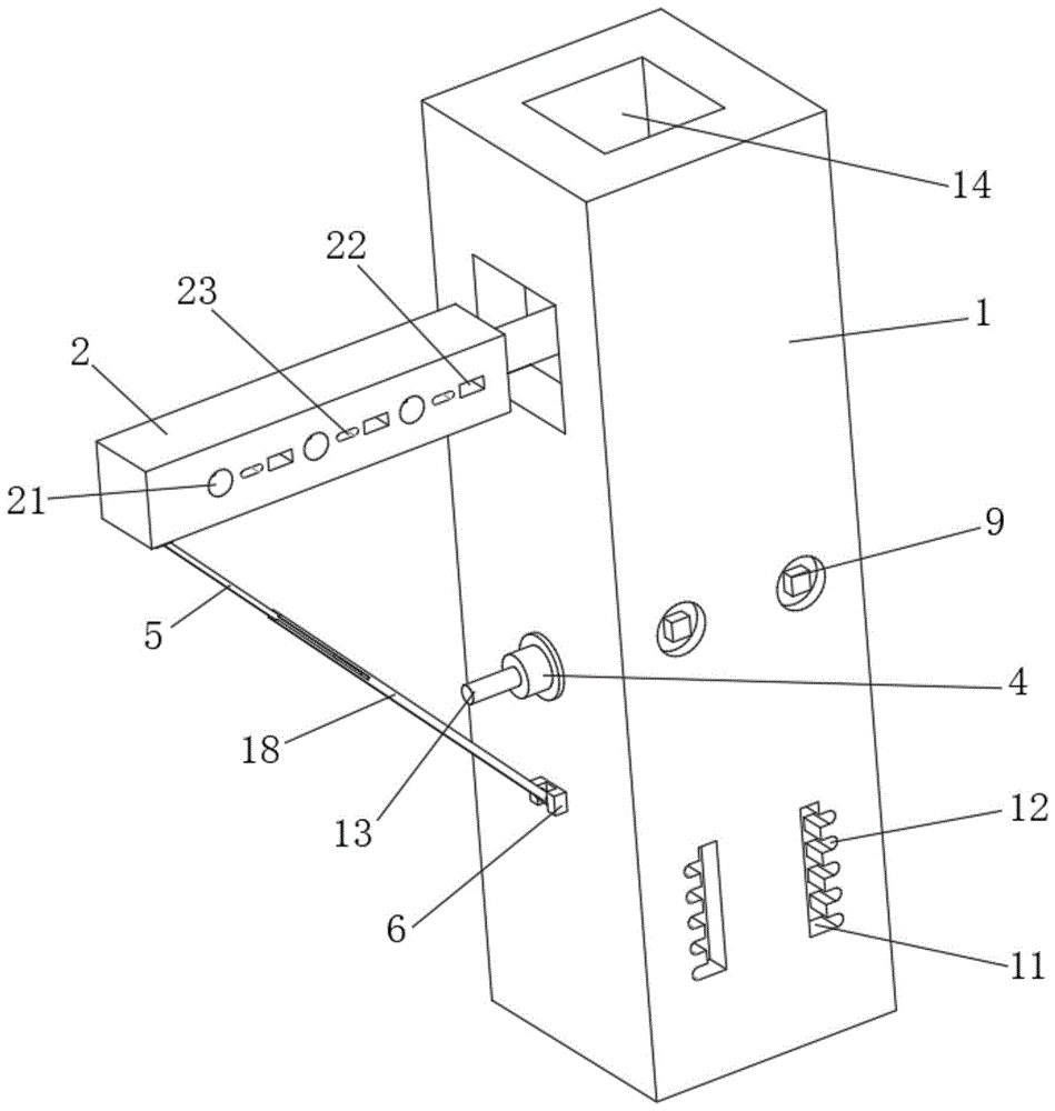
FIG. 1 is a schematic structural view of the present invention;
FIG. 2 is a front view of the present invention;
FIG. 3 is a schematic perspective view of the present invention;
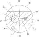
FIG. 4 is an enlarged view of the structure at B in FIG. 1;
FIG. 5 is an enlarged view of the structure at A in FIG. 1;
fig. 6 is a perspective view of a second bar according to the present invention.
In the figure: 1. a cable support; 2. a support arm; 3. a cable; 4. a fixed tube; 5. a first support bar; 6. hinging seat; 7. an extension rod; 8. pulling a rope; 9. a control panel; 10. a bayonet lock; 11. a lifting groove; 12. a card slot; 13. a pull rod; 14. a lifting inner cavity; 15. a rack; 16. a gear; 17. a lifting column; 18. a second support bar; 19. a steering wheel; 20. an adjustment column; 21. a jack; 22. pressing a groove; 23. an open slot; 24. a sleeve; 25. a slot; 26. the long groove is penetrated; 27. a first spring; 28. a baffle plate; 29. a support; 30. a push handle; 31. a clamping block; 32. a sliding beam; 33. a second spring; 34. a limiting plate; 35. cushion plate.
Detailed Description
The technical solutions in the embodiments of the present invention will be clearly and completely described below with reference to the drawings in the embodiments of the present invention, and it is obvious that the described embodiments are only a part of the embodiments of the present invention, and not all of the embodiments. All other embodiments, which can be derived by a person skilled in the art from the embodiments given herein without making any creative effort, shall fall within the protection scope of the present invention.
Referring to fig. 1 to 6, the present invention provides a technical solution:
an earthquake-proof erection device for mounting electromechanical cables of a building comprises a cable support post 1, a pair of support arms 2 are rotatably mounted on the left and right sides of the upper end of the cable support post 1, the end part of each support arm 2 extends into an inner cavity of the cable support post 1, a gear 16 is arranged at the end part of each support arm 2, a rack 15 meshed with the gear 16 is arranged in the inner cavity of the cable support post 1, the lower end of the rack 15 is adjusted in height through a lifting column 17, the inner cavity of the upper end of the cable support post 1 is provided with a lifting inner cavity 14, the outer wall of the front end of the cable support post 1 is provided with a control panel 9 electrically connected with the lifting column 17, the lifting column 17 is vertically mounted in the lifting inner cavity 14, the upper end of the lifting column 17 is fixedly connected with the rack 15 meshed with the gear 16, the telescopic height of the lifting column 17 is controlled through the control panel 9, the length of the rack 15 meshed with the gear 16 is adjusted, and the lateral rotation angle of the support arms 2 is roughly adjusted, after adjustment, the supporting arm 2 can rotate relatively in the gap between adjacent teeth.
The lower extreme outer wall of cable strut 1 is provided with the telescopic bracing piece of being connected with support arm 2 lower extreme support, all be provided with free bearing 6 on support arm 2 and the cable strut 1, telescopic bracing piece includes first branch 5 and second branch 18, the tip of first branch 5 and second branch 18 all is provided with sleeve pipe 24, first branch 5 and second branch 18 rotate through sleeve pipe 24 and install on free bearing 6, the one end mutual slip grafting that first branch 5 and second branch 18 are relative, cooperation through free bearing 6 and sleeve pipe 24, realize the rotary type installation of first branch 5 and second branch 18.
The end part of the second support rod 18 is provided with a slot 25, the front inner wall and the rear inner wall of the slot 25 are provided with through elongated slots 26 which are mutually penetrated, the first support rod 5 is slidably inserted in the slot 25, the end part of the first support rod 5 is provided with an extension rod 7 which is slidably installed in the through elongated slots 26, the extension rod 7 is fastened on the outer wall of the second support rod 18 through a nut, the first support rod 5 is slidably inserted in the slot 25, the length of the support rod is further adapted under the driving of the gear 16, and the fastening of the length is realized through the extension rod 7 after the coarse adjustment is finished.
The outer wall of cable pillar 1 is provided with the fixed pipe 4 of screw-up installation, it has pull rod 13 to slide in the fixed pipe 4 and peg graft, the one end of pull rod 13 extends to the outside of fixed pipe 4 and connects second branch 18 through stay cord 8, the opposite side of pull rod 13 passes through the horizontal pressfitting of spring at the outer wall of cable pillar 1, pull rod 13 is arranged in the one end of fixed pipe 4 and passes through stay cord 8 and connect regulation post 20, stay cord 8 passes through the vertical downwardly extending to lift groove 11 of directive wheel 19, be provided with a pair of stay cord 8 of connecting telescopic bracing piece in the lower extreme inner chamber of cable pillar 1, the lower extreme of stay cord 8 is connected with regulation post 20, cooperation through stay cord 8 and pull rod 13, realize being connected of second branch 18 and regulation post 20, and then reach the traction to second branch 18 through the altitude mixture control to regulation post 20.
The front end of the cable strut 1 is provided with a lifting groove 11 with a clamping groove 12, the adjusting column 20 is provided with a bayonet 10 inserted in the clamping groove 12, the end part of the pull rope 8 is fixedly connected with the adjusting column 20, the lower end of the adjusting column 20 is provided with a bracket 29, the bayonet 10 is inserted on the bracket 29 in a transverse sliding manner, two ends of the bayonet 10 are provided with baffle plates 28, the outer wall of the bayonet 10 is provided with a first spring 27 which is transversely sleeved, the first spring 27 is sleeved on the outer wall of the bayonet 10 close to one side of the clamping groove 12, the first spring 27 is pressed between the bracket 29 and the baffle plate 28, the fixed-length supporting rod is transversely pulled through the adjustment of the adjusting column 20 in the lifting groove 11, the pull rod 13 extrudes the spring in the fixed tube 4, the fixed-length supporting rod is further driven to transversely rotate, the supporting arm 2 is accurately adjusted in a small angle, after the adjustment is completed, the bayonet 10 is inserted in the clamping groove 12, a height fixation of the adjusting column 20 is achieved.
Be provided with the multiunit of linear distribution on the support arm 2 and be used for cable 3 to run through jack 21 of pegging graft, horizontal slidable mounting has the grip block 31 of centre gripping cable 3 in the jack 21, the position that lies in jack 21 one side on the support arm 2 is provided with the indent 22 that runs through from beginning to end, it has horizontal slip's sliding beam 32 to peg graft between indent 22 and the jack 21, sliding beam 32's one end is provided with the grip block 31 that lies in jack 21, sliding beam 32's the other end is provided with the limiting plate 34 that lies in indent 22, utilize jack 21 to realize cable 3's the grafting that runs through, drive grip block 31 pressfitting cable 3 through sliding beam 32, reach fastening cable 3's purpose.
The inner wall of the jack 21 opposite to the clamping block 31 is provided with a buffer cushion plate 35, the sliding beam 32 is sleeved with a second spring 33 in the transverse direction, two ends of the second spring 33 are pressed between the inner walls of the limiting plate 34 and the pressing groove 22, an oblong opening groove 23 is arranged between the jack 21 and the pressing groove 22, the opening groove 23 is communicated with the sliding beam 32, the sliding beam 32 is provided with a push handle 30 extending to the outer side of the opening groove 23, the second spring 33 is extruded by the aid of transverse sliding of the push handle 30 in the opening groove 23, the cable 3 smoothly penetrates through the jack 21, the push handle 30 is loosened, and under the reset elastic force of the second spring 33, the cable 3 is tightly clamped between the clamping block 31 and the buffer cushion plate 35.
The working principle is as follows: at first, through the flexible height of control panel 9 control lift post 17, and then reach the length of adjusting rack 15 meshing on gear 16, reach the coarse adjustment to 2 side direction turned angle of support arm, after the regulation, support arm 2 can be in the relative rotation in the clearance between adjacent tooth, cooperation through free bearing 6 and sleeve pipe 24, realize the rotary type installation of first branch 5 and second branch 18, peg graft through the slip of first branch 5 in slot 25, and then make under the gear 16 drive, realize the adaptation of support bar length, realize the fastening of length through extension rod 7 after the coarse adjustment is accomplished.
Through the cooperation of stay cord 8 and pull rod 13, realize being connected of second branch 18 and regulation post 20, and then reach the drawing to second branch 18 through the altitude mixture control to regulation post 20, realize transversely drawing the fixed length bracing piece through the regulation of regulation post 20 height in lift groove 11, make pull rod 13 extrude the spring in the fixed pipe 4, and then drive the bracing piece transverse rotation of fixed length, realize carrying out the accurate regulation of small angle to support arm 2, adjust the completion back, through bayonet lock 10 and 12 grafting of draw-in groove, realize the height-fixing to regulation post 20.
Utilize jack 21 to realize the grafting that runs through of cable 3, drive grip block 31 pressfitting cable 3 through sliding beam 32, reach the purpose of fastening cable 3, utilize the horizontal slip of push handle 30 in open slot 23, realize the extrusion to second spring 33 for cable 3 is smooth to run through jack 21, then loosens push handle 30, under the elasticity that resets of second spring 33, makes cable 3 fastening centre gripping between grip block 31 and buffer pad 35.
The lifting column 17 is an electric telescopic device commonly used in the field and will not be described in detail.
Although embodiments of the present invention have been shown and described, it will be appreciated by those skilled in the art that changes, modifications, substitutions and alterations can be made in these embodiments without departing from the principles and spirit of the invention, the scope of which is defined in the appended claims and their equivalents.