CN114191225B - A device for treating burns and scalds in general surgery - Google Patents
A device for treating burns and scalds in general surgery Download PDFInfo
- Publication number
- CN114191225B CN114191225B CN202210084256.XA CN202210084256A CN114191225B CN 114191225 B CN114191225 B CN 114191225B CN 202210084256 A CN202210084256 A CN 202210084256A CN 114191225 B CN114191225 B CN 114191225B
- Authority
- CN
- China
- Prior art keywords
- patient
- groove
- plate
- sliding
- support plate
- Prior art date
- Legal status (The legal status is an assumption and is not a legal conclusion. Google has not performed a legal analysis and makes no representation as to the accuracy of the status listed.)
- Expired - Fee Related
Links
Images

Classifications
-
- A—HUMAN NECESSITIES
- A61—MEDICAL OR VETERINARY SCIENCE; HYGIENE
- A61G—TRANSPORT, PERSONAL CONVEYANCES OR ACCOMMODATION SPECIALLY ADAPTED FOR PATIENTS OR DISABLED PERSONS; OPERATING TABLES OR CHAIRS; CHAIRS FOR DENTISTRY; FUNERAL DEVICES
- A61G13/00—Operating tables; Auxiliary appliances therefor
- A61G13/10—Parts, details or accessories
- A61G13/12—Rests specially adapted therefor; Arrangements of patient-supporting surfaces
- A61G13/1205—Rests specially adapted therefor; Arrangements of patient-supporting surfaces for specific parts of the body
- A61G13/121—Head or neck
-
- A—HUMAN NECESSITIES
- A61—MEDICAL OR VETERINARY SCIENCE; HYGIENE
- A61G—TRANSPORT, PERSONAL CONVEYANCES OR ACCOMMODATION SPECIALLY ADAPTED FOR PATIENTS OR DISABLED PERSONS; OPERATING TABLES OR CHAIRS; CHAIRS FOR DENTISTRY; FUNERAL DEVICES
- A61G13/00—Operating tables; Auxiliary appliances therefor
- A61G13/10—Parts, details or accessories
- A61G13/12—Rests specially adapted therefor; Arrangements of patient-supporting surfaces
- A61G13/1205—Rests specially adapted therefor; Arrangements of patient-supporting surfaces for specific parts of the body
- A61G13/1245—Knees, upper or lower legs
-
- A—HUMAN NECESSITIES
- A61—MEDICAL OR VETERINARY SCIENCE; HYGIENE
- A61M—DEVICES FOR INTRODUCING MEDIA INTO, OR ONTO, THE BODY; DEVICES FOR TRANSDUCING BODY MEDIA OR FOR TAKING MEDIA FROM THE BODY; DEVICES FOR PRODUCING OR ENDING SLEEP OR STUPOR
- A61M3/00—Medical syringes, e.g. enemata; Irrigators
- A61M3/02—Enemata; Irrigators
Landscapes
- Health & Medical Sciences (AREA)
- Engineering & Computer Science (AREA)
- Biomedical Technology (AREA)
- Life Sciences & Earth Sciences (AREA)
- Animal Behavior & Ethology (AREA)
- General Health & Medical Sciences (AREA)
- Public Health (AREA)
- Veterinary Medicine (AREA)
- Anesthesiology (AREA)
- Heart & Thoracic Surgery (AREA)
- Hematology (AREA)
- Neurosurgery (AREA)
- Otolaryngology (AREA)
- Accommodation For Nursing Or Treatment Tables (AREA)
Abstract
本发明涉及医疗器械技术领域,且公开了一种普外科烧烫伤治疗装置,包括支撑板、以及固定安装在支撑板用以清洗的清理机构,所述支撑板的左右两侧均设置有加长支撑板长度的加长机构;所述加长机构包括与支撑板铰接的连接轴。该普外科烧烫伤治疗装置,通过在使用时,将病人放置在支撑板上,通过控制连接板向上转动,在转动过程中可以对患者头部的角度进行改变,可以根据不同患者的舒适度进行调整,提高患者就医时的体验感,在连接板向上转动时,配合连接绳和导向轮的作用,可以带动盖合板在开口的内部滑动,从而在调整患者头部角度时,随着头部角度的抬高,可以适当通过盖合板调整开口的大小,来实现减小患者皮肤与支撑板接触的面积。
The invention relates to the technical field of medical devices, and discloses a burn and scald treatment device for general surgery, which includes a support plate and a cleaning mechanism fixedly installed on the support plate for cleaning, and the left and right sides of the support plate are provided with extended supports An extension mechanism for the length of the board; the extension mechanism includes a connecting shaft hinged to the support board. The device for treating burns and scalds in general surgery can change the angle of the patient's head during the rotation process by placing the patient on the support plate and controlling the upward rotation of the connecting plate, which can be adjusted according to the comfort of different patients. Adjustment to improve the experience of patients when they go to the doctor. When the connecting plate is turned upwards, with the function of the connecting rope and the guide wheel, it can drive the cover to slide inside the opening, so that when the patient’s head angle is adjusted, it will follow the angle of the head. The size of the opening can be appropriately adjusted through the cover plate to reduce the contact area between the patient's skin and the support plate.
Description
技术领域technical field
本发明涉及医疗器械技术领域,具体为一种普外科烧烫伤治疗装置。The invention relates to the technical field of medical devices, in particular to a device for treating burns and scalds in general surgery.
背景技术Background technique
普外科是以手术为主要方法治疗肝脏、胆道、胰腺等其他疾病的临床学科,是外科系统最大的专科,目前烧烫伤患者也在普外科进行治疗,在对大面积烧烫伤患者进行治疗时,对患者皮肤与治疗装置接触面积要求非常高,如果患者皮肤大面积与治疗装置接触,则导致清洗工作不方便进行。General surgery is a clinical discipline that treats liver, biliary tract, pancreas and other diseases with surgery as the main method. It is the largest specialty in the surgical system. Currently, burn patients are also treated in general surgery. When treating patients with large area burns, The requirement for the contact area between the patient's skin and the treatment device is very high. If the patient's skin is in contact with the treatment device in a large area, the cleaning work will be inconvenient.
所以针对上述提出的问题,现在急需一种在医护人员对烧烫伤患者进行治疗时,可以改变患者皮肤与治疗装置的接触面积,并且不会给患者带来不适感,从而给医护人员带来方便,方便对患者进行伤口清洗和涂药。Therefore, for the above-mentioned problems, there is an urgent need for a medical device that can change the contact area between the patient's skin and the treatment device when the medical staff treats the burn patient, and will not bring discomfort to the patient, thereby bringing convenience to the medical staff. , It is convenient to clean the wound and apply medicine to the patient.
发明内容Contents of the invention
针对现有技术的不足,本发明提供了一种普外科烧烫伤治疗装置,具备给医护人员带来方便,节省清洗时间,给患者减轻反复翻身带来的疼痛等优点。Aiming at the deficiencies of the prior art, the present invention provides a device for treating burns and scalds in general surgery, which has the advantages of bringing convenience to medical staff, saving cleaning time, and reducing pain caused by repeated turning over for patients.
为实现上述给医护人员带来方便,节省清洗时间,给患者减轻反复翻身带来的疼痛等目的,本发明提供如下技术方案:一种普外科烧烫伤治疗装置,包括支撑板、以及固定安装在支撑板用以清洗的清理机构,所述支撑板的左右两侧均设置有加长支撑板长度的加长机构;In order to achieve the above purposes of bringing convenience to medical staff, saving cleaning time, and reducing pain caused by repeated turning over for patients, the present invention provides the following technical solutions: a burn treatment device for general surgery, including a support plate, and fixedly installed on The support plate is used as a cleaning mechanism for cleaning, and the left and right sides of the support plate are provided with lengthening mechanisms to lengthen the length of the support plate;
所述加长机构包括与支撑板铰接的连接轴,所述连接轴上转动连接有上下转动的连接板,所述连接板的前后两侧均铰接有对称分布的连接杆,所述设备本体上开设有与连接杆相对的四组滑动槽,所述滑动槽的内部滑动连接有滑动块,所述滑动块与连接杆铰接;The lengthening mechanism includes a connecting shaft hinged to the support plate, a connecting plate that rotates up and down is connected to the connecting shaft, and symmetrically distributed connecting rods are hinged on the front and rear sides of the connecting plate. There are four sets of sliding grooves opposite to the connecting rod, the inside of the sliding groove is slidably connected with a sliding block, and the sliding block is hinged to the connecting rod;
所述支撑板的右侧上端设置有减小患者皮肤接触面积的开口,所述支撑板的下方且在开口的左侧转动连接有导向轮,所述开口的内部滑动连接有盖合板,所述盖合板的面积与开口相对应,所述导向轮上线连接有将盖合板与连接板联合的连接绳,在使用时,将病人放置在支撑板上,通过控制连接板向上转动,在转动过程中可以对患者头部的角度进行改变,可以根据不同患者的舒适度进行调整,提高患者就医时的体验感,在连接板向上转动时,配合连接绳和导向轮的作用,可以带动盖合板在开口的内部滑动,从而在调整患者头部角度时,随着头部角度的抬高,可以适当通过盖合板调整开口的大小,来实现减小患者皮肤与支撑板接触的面积。The upper right side of the support plate is provided with an opening to reduce the patient’s skin contact area, a guide wheel is connected to the bottom of the support plate and rotated on the left side of the opening, and a cover plate is slidably connected to the inside of the opening. The area of the cover plate corresponds to the opening, and the upper line of the guide wheel is connected with a connecting rope that combines the cover plate and the connecting plate. When in use, the patient is placed on the support plate, and the connecting plate is controlled to rotate upwards. The angle of the patient's head can be changed, and it can be adjusted according to the comfort of different patients to improve the patient's experience when seeing a doctor. When the connecting plate is turned upwards, with the function of the connecting rope and the guide wheel, it can drive the cover plate in the opening Therefore, when adjusting the angle of the patient's head, as the angle of the head rises, the size of the opening can be appropriately adjusted through the cover plate to reduce the contact area between the patient's skin and the support plate.
进一步,所述滑动块的内部滑动连接有与连接杆铰接调整机构;Further, the inside of the sliding block is slidably connected with a hinged adjustment mechanism with the connecting rod;
所述调整机构包括在滑动块上滑动且用于定位的连接块,所述连接块的上方铰接有对称分布的两个导杆,两个所述导杆的相背面上均铰接有限位杆,所述滑动槽的内部固定安装有与限位杆相对应的限位齿牙,通过连接板在连接轴上转动时,会配合连接杆带动滑动块在滑动槽的内部滑动,在连接板向上转动时,滑动槽内部的滑动块会向上滑动,因为限位齿牙与限位杆的设计,限位杆在限位齿牙上很容易向上滑动,然后在调整好连接板的角度时,此时可以限位杆插入到限位齿牙之间,可以对滑动块的位置进行固定,从而保证了连接板的角度固定,方便为患者提供更加舒适的就医姿势,在不需要时加长机构时,可以通过医护人员向下按压连接板,连接板配合连接杆给连接块施加压力,连接块在滑动块的内部向下滑动,从而可以配合两个导杆带动限位杆向内缩回,与限位齿牙脱离,从而可以将加长机构收起,在不使用时,节省了空间。The adjustment mechanism includes a connecting block that slides on the sliding block and is used for positioning. Two guide rods symmetrically distributed are hinged above the connecting block, and limit rods are hinged on the opposite sides of the two guide rods. The interior of the sliding groove is fixedly equipped with limiting teeth corresponding to the limiting rod. When the connecting plate rotates on the connecting shaft, the connecting rod will drive the sliding block to slide inside the sliding groove and rotate upward on the connecting plate. , the sliding block inside the sliding groove will slide upwards, because of the design of the limit teeth and the limit rod, the limit rod can easily slide upward on the limit teeth, and then when the angle of the connecting plate is adjusted, at this time The limit rod can be inserted between the limit teeth, and the position of the sliding block can be fixed, thus ensuring the fixed angle of the connecting plate, which is convenient for providing patients with a more comfortable medical posture. When the mechanism is not needed, it can be extended. When the medical personnel press down on the connecting plate, the connecting plate cooperates with the connecting rod to exert pressure on the connecting block, and the connecting block slides downward inside the sliding block, so that the two guide rods can drive the limit rod to retract inwards, and the limit rod can be retracted inwardly with the limit The teeth are disengaged, so that the extension mechanism can be put away, saving space when not in use.
进一步,所述滑动块的下方与滑动槽之间设置有用于复位的第一弹簧,所述连接块与滑动块的内部之间设置有第二弹簧,两个所述限位杆的相对面上设置有第三弹簧,各个弹簧的设计,帮助与其连接的机构快速复位。Further, a first spring for reset is provided between the bottom of the sliding block and the sliding groove, a second spring is provided between the connecting block and the inside of the sliding block, and the two opposing surfaces of the limit rods A third spring is provided, and the design of each spring helps the mechanism connected to it to reset quickly.
进一步,所述开口的内壁上开设有盖合板滑动的导向槽,所述盖合板的两侧设置有在导向槽内部滑动的定位杆,所述支撑板在开口的左侧开设有供盖合板插入的隐藏槽,所述盖合板的左侧与隐藏槽之间固定安装有第四弹簧,通过在盖合板向隐藏槽处滑动时,开口逐渐被打开,定位杆和导向槽的设计,可以更加方便盖合板在隐藏槽的内部滑动。Further, the inner wall of the opening is provided with a guide groove for the sliding of the cover plate, positioning rods sliding inside the guide groove are provided on both sides of the cover plate, and the support plate is opened on the left side of the opening for the insertion of the cover plate. A fourth spring is fixedly installed between the left side of the cover plate and the hidden groove. When the cover plate slides to the hidden groove, the opening is gradually opened, and the design of the positioning rod and the guide groove can be more convenient. The flap slides inside the concealed slot.
进一步,所述盖合板的左侧固定安装有一组牵引杆,所述隐藏槽的左侧开设有一组连接槽,所述连接槽的内部在靠近牵引杆的端面上滑动连接有移动块,所述移动块与牵引杆同步在连接槽的内部运动,所述连接槽的内部固定安装导向框,所述导向框的内部滑动连接有抵触块,所述抵触块与移动块之间铰接有抵触杆,所述抵触块的上方固定安装有伸出杆,两个所述伸出杆之间设置有抬身患者下半身的支撑架。Further, a set of drawbars is fixedly installed on the left side of the cover plate, and a set of connection grooves are opened on the left side of the hidden groove, and a moving block is slidably connected to the end surface of the connection grooves close to the drawbars. The moving block and the draw bar move synchronously inside the connecting groove, the inside of the connecting groove is fixedly installed with a guide frame, the inside of the guide frame is slidably connected with a conflicting block, and a conflicting rod is hinged between the conflicting block and the moving block, An extension rod is fixedly installed above the collision block, and a support frame for lifting the patient's lower body is arranged between the two extension rods.
进一步,两个导向框的相对面上设置有与支撑板下方固定连接的固定框,所述固定框的内部滑动连接有与抵触块同步运动的挤压板,所述固定框内部且在挤压板的上方固定安装有向内吸气的连接囊,所述连接囊外接有制冷组件。Further, a fixed frame fixedly connected to the bottom of the support plate is provided on the opposite surface of the two guide frames, and an extrusion plate that moves synchronously with the conflicting block is slidably connected inside the fixed frame. A connection bag that inhales air inwardly is fixedly installed above the plate, and the connection bag is externally connected with a refrigeration assembly.
进一步,所述连接槽的上方开设有贯穿于支撑板的贯穿槽,所述贯穿槽的槽宽小于连接槽的宽度,所述伸出杆可以通过贯穿槽延伸至支撑板的上方与支撑架连接,所述连接囊与支撑架之间连接有橡胶软管,所述支撑架在与人体皮肤接触的端面上设置有橡胶垫,所述橡胶垫为透气设计。Further, above the connection groove, there is a through groove through the support plate, the groove width of the through groove is smaller than the width of the connection groove, and the extension rod can extend to the top of the support plate through the through groove and connect with the support frame A rubber hose is connected between the connecting bag and the support frame, and a rubber pad is provided on the end surface of the support frame in contact with human skin, and the rubber pad is designed to be breathable.
进一步,所述支撑板的上方固定安装有清洗架,所述清洗架上滑动连接有出水箱,所述出水箱的前端固定安装有滑动杆,所述滑动杆上滑动连接有清洗框。Further, a cleaning frame is fixedly installed above the support plate, a water outlet box is slidably connected to the cleaning frame, a sliding rod is fixedly installed at the front end of the water outlet box, and a cleaning frame is slidably connected to the sliding rod.
进一步,所述支撑板的下方设置有用于支撑的四组支撑腿,所述滑动槽开设在支撑腿的内部,所述支撑板右侧的加长机构用于承载患者头部,所述支撑板左侧的加长机构用于承载患者腿部。Further, four sets of support legs are provided under the support plate for support, the sliding grooves are set inside the support legs, the extension mechanism on the right side of the support plate is used to carry the patient’s head, and the left side of the support plate The side extensions are used to support the patient's legs.
与现有技术相比,本发明提供了一种普外科烧烫伤治疗装置,具备以下有益效果:Compared with the prior art, the present invention provides a device for treating burns and scalds in general surgery, which has the following beneficial effects:
1、该普外科烧烫伤治疗装置,通过在使用时,将病人放置在支撑板上,通过控制连接板向上转动,在转动过程中可以对患者头部的角度进行改变,可以根据不同患者的舒适度进行调整,提高患者就医时的体验感,在连接板向上转动时,配合连接绳和导向轮的作用,可以带动盖合板在开口的内部滑动,从而在调整患者头部角度时,随着头部角度的抬高,可以适当通过盖合板调整开口的大小,来实现减小患者皮肤与支撑板接触的面积。1. The device for treating burns and scalds in general surgery can change the angle of the patient's head during the rotation process by placing the patient on the support plate and controlling the upward rotation of the connecting plate, which can be adjusted according to the comfort of different patients. Adjust the degree to improve the patient's experience when going to the doctor. When the connecting plate rotates upwards, with the function of the connecting rope and the guide wheel, it can drive the cover to slide inside the opening, so that when adjusting the angle of the patient's head, it will follow the direction of the head. To increase the angle of the head, the size of the opening can be appropriately adjusted through the cover plate to reduce the contact area between the patient's skin and the support plate.
2、该普外科烧烫伤治疗装置,通过限位杆与限位齿牙之间连接关系的设计,在限位杆向上移动时,很容易移动,在滑动块移动到滑动槽的上方时,向下滑动变得很困难,从而可以对连接板的角度进行固定,调整患者就医姿势,满足患者不同要求,同时在医护人员向下按压连接板时,连接块在滑动块的内部向下滑动,从而可以配合两个导杆带动限位杆向内缩回,与限位齿牙脱离,从而可以将加长机构收起,在不使用时,节省了空间。2. The burn and scald treatment device for general surgery, through the design of the connection relationship between the limit rod and the limit teeth, when the limit rod moves upward, it is easy to move, and when the sliding block moves to the top of the sliding groove, it moves toward the It becomes very difficult to slide down, so that the angle of the connecting plate can be fixed, and the patient’s posture can be adjusted to meet the different requirements of patients. At the same time, when the medical staff presses the connecting plate downward, the connecting block slides down inside the sliding block, thereby The two guide rods can be used to drive the limit rod to retract inwardly and disengage from the limit teeth, so that the extension mechanism can be put away, saving space when not in use.
3、该普外科烧烫伤治疗装置,通过盖合板在隐藏槽的内部滑动时,带动牵引杆在推动移动块在连接槽的内部向左侧滑动,在此过程中,配合抵触杆带动抵触块在导向框的内部向下滑动,从而再配合上伸出杆的作用,带动支撑板上方的支撑架向下降低高度,从而在抬升患者上半身的过程中,可以同时配合将患者下半身进行降低高度,避免人体与支撑板着力点变小时,会给患者带来不舒适感。3. The device for treating burns and scalds in general surgery, when the cover plate slides inside the hidden groove, drives the traction bar to push the moving block to slide to the left inside the connecting groove. The inside of the guide frame slides downwards, and then cooperates with the function of the upper extension rod to drive the support frame above the support plate to lower its height downwards, so that in the process of lifting the upper body of the patient, it can cooperate with lowering the lower body of the patient at the same time to avoid The smaller the force point of the human body and the support plate will bring discomfort to the patient.
附图说明Description of drawings
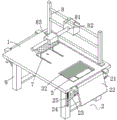
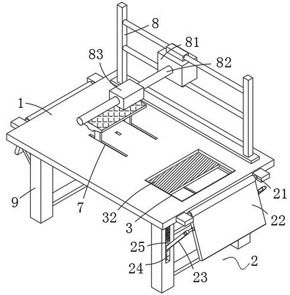
图1为本发明结构整体示意图;Fig. 1 is the overall schematic diagram of the structure of the present invention;
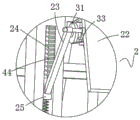
图2为本发明加长机构与调整机构连接示意图;Fig. 2 is a schematic diagram of the connection between the extension mechanism and the adjustment mechanism of the present invention;
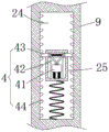
图3为本发明调整机构剖视图;Fig. 3 is a sectional view of the adjustment mechanism of the present invention;
图4为本发明支撑板结构仰视图;Fig. 4 is a bottom view of the support plate structure of the present invention;
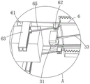
图5为本发明图4中A结构放大示意图;Fig. 5 is the enlarged schematic diagram of structure A in Fig. 4 of the present invention;
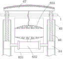
图6为本发明固定框结构剖视图;Fig. 6 is a sectional view of the fixed frame structure of the present invention;
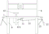
图7为本发明整体正视示意图。Fig. 7 is a schematic front view of the whole of the present invention.
图中:1、支撑板;2、加长机构;21、连接轴;22、连接板;23、连接杆;24、滑动槽;25、滑动块;3、开口;31、导向轮;32、盖合板;33、连接绳;4、调整机构;41、连接块;42、导杆;43、限位杆;44、限位齿牙; 6、牵引杆;61、连接槽;62、移动块;63、导向框;631、固定框;632、挤压板;633、连接囊;64、抵触块;65、抵触杆;66、伸出杆;67、支撑架;7、贯穿槽;8、清洗架;81、出水箱;82、滑动杆;83、清洗框;9、支撑腿。In the figure: 1, support plate; 2, extension mechanism; 21, connecting shaft; 22, connecting plate; 23, connecting rod; 24, sliding groove; 25, sliding block; 3, opening; 31, guide wheel; 32, cover Plywood; 33, connecting rope; 4, adjustment mechanism; 41, connecting block; 42, guide rod; 43, limit rod; 44, limit tooth; 6, draw bar; 61, connecting groove; 62, moving block; 63. Guide frame; 631. Fixed frame; 632. Squeeze plate; 633. Connecting bag; 64. Interference block; 65. Interference rod; 66. Extension rod; 67. Support frame; 7. Through groove; 8. Cleaning Frame; 81, water outlet tank; 82, slide bar; 83, cleaning frame; 9, support leg.
具体实施方式Detailed ways
下面将结合本发明实施例中的附图,对本发明实施例中的技术方案进行清楚、完整地描述,显然,所描述的实施例仅仅是本发明一部分实施例,而不是全部的实施例。基于本发明中的实施例,本领域普通技术人员在没有做出创造性劳动前提下所获得的所有其他实施例,都属于本发明保护的范围。The following will clearly and completely describe the technical solutions in the embodiments of the present invention with reference to the accompanying drawings in the embodiments of the present invention. Obviously, the described embodiments are only some, not all, embodiments of the present invention. Based on the embodiments of the present invention, all other embodiments obtained by persons of ordinary skill in the art without making creative efforts belong to the protection scope of the present invention.
如图1和2,本发明提供了一种普外科烧烫伤治疗装置,包括支撑板1、以及固定安装在支撑板1用以清洗的清理机构,支撑板1的左右两侧均设置有加长支撑板长度的加长机构2;As shown in Figures 1 and 2, the present invention provides a general surgery burn and scald treatment device, including a
加长机构2包括与支撑板1铰接的连接轴21,连接轴21上转动连接有上下转动的连接板22,连接板22的前后两侧均铰接有对称分布的连接杆23,设备本体1上开设有与连接杆23相对的四组滑动槽24,滑动槽24的内部滑动连接有滑动块25,滑动块25与连接杆23铰接;The
支撑板1的右侧上端设置有减小患者皮肤接触面积的开口3,支撑板1的下方且在开口3的左侧转动连接有导向轮31,开口3的内部滑动连接有盖合板32,盖合板32的面积与开口3相对应,导向轮31上线连接有将盖合板32与连接板22联合的连接绳33。The upper right side of the
本发明实施例在使用时,将病人放置在支撑板1上,通过控制连接板22向上转动,在转动过程中可以对患者头部的角度进行改变,可以根据不同患者的舒适度进行调整,提高患者就医时的体验感,在连接板22向上转动时,配合连接绳33和导向轮31的作用,可以带动盖合板32在开口3的内部滑动,从而在调整患者头部角度时,随着头部角度的抬高,可以适当通过盖合板32调整开口3的大小,来实现减小患者皮肤与支撑板1接触的面积,通过人体构造分析可知,在背部抬升角度越高时,其腰间部分受力就会变小,这样在增加开口3的面积时,就不会给患者腰部因为受力点减小而带来的损伤。When the embodiment of the present invention is in use, the patient is placed on the
如图2和3,本发明实施例滑动块25的内部滑动连接有与连接杆23铰接调整机构4;调整机构4包括在滑动块25上滑动且用于定位的连接块41,连接块41的上方铰接有对称分布的两个导杆42,两个导杆42的相背面上均铰接有限位杆43,滑动槽24的内部固定安装有与限位杆43相对应的限位齿牙44。As Fig. 2 and 3, the
通过连接板22在连接轴21上转动时,会配合连接杆23带动滑动块25在滑动槽24的内部滑动,在连接板22向上转动时,滑动槽24内部的滑动块25会向上滑动,因为限位齿牙44与限位杆43的设计,限位杆43在限位齿牙44上很容易向上滑动,然后在调整好连接板22的角度时,此时可以限位杆43插入到限位齿牙44之间,可以对滑动块25的位置进行固定,从而保证了连接板22的角度固定,方便为患者提供更加舒适的就医姿势,在不需要时加长机构2时,可以通过医护人员向下按压连接板22,连接板22配合连接杆23给连接块41施加压力,连接块41在滑动块25的内部向下滑动,从而可以配合两个导杆42带动限位杆43向内缩回,与限位齿牙44脱离,从而可以将加长机构2收起,在不使用时,节省了空间。When the connecting
如图3,本发明实施例滑动块25的下方与滑动槽24之间设置有用于复位的第一弹簧,连接块41与滑动块25的内部之间设置有第二弹簧,两个限位杆43的相对面上设置有第三弹簧,各个弹簧的设计,帮助与其连接的机构快速复位。As shown in Fig. 3, a first spring for resetting is provided between the bottom of the sliding
如图4至6,本发明实施例开口3的内壁上开设有盖合板32滑动的导向槽,盖合板32的两侧设置有在导向槽内部滑动的定位杆,支撑板1在开口3的左侧开设有供盖合板32插入的隐藏槽,盖合板32的左侧与隐藏槽之间固定安装有第四弹簧,通过在盖合板32向隐藏槽处滑动时,开口3逐渐被打开,定位杆和导向槽的设计,可以更加方便盖合板32在隐藏槽的内部滑动。As shown in Figures 4 to 6, the inner wall of the
盖合板32的左侧固定安装有一组牵引杆6,隐藏槽的左侧开设有一组连接槽61,连接槽61的内部在靠近牵引杆6的端面上滑动连接有移动块62,移动块62与牵引杆6同步在连接槽61的内部运动,连接槽61的内部固定安装导向框63,两个导向框63的相对面上设置有与支撑板1下方固定连接的固定框631,固定框631的内部滑动连接有与抵触块64同步运动的挤压板632,固定框631内部且在挤压板632的上方固定安装有向内吸气的连接囊633,连接囊633外接有制冷组件,导向框63的内部滑动连接有抵触块64,抵触块64与移动块62之间铰接有抵触杆65,抵触块64的上方固定安装有伸出杆66,两个伸出杆66之间设置有抬身患者下半身的支撑架67,连接槽61的上方开设有贯穿于支撑板1的贯穿槽7,贯穿槽7的槽宽小于连接槽61的宽度,伸出杆66可以通过贯穿槽7延伸至支撑板1的上方与支撑架67连接,连接囊633与支撑架67之间连接有橡胶软管,支撑架67在与人体皮肤接触的端面上设置有橡胶垫,橡胶垫为透气设计。A group of
通过盖合板32在隐藏槽的内部滑动时,带动牵引杆6在推动移动块62在连接槽61的内部向左侧滑动,在此过程中,配合抵触杆65带动抵触块64在导向框63的内部向下滑动,从而再配合上伸出杆66的作用,带动支撑板1上方的支撑架67向下降低高度,从而在抬升患者上半身的过程中,可以同时配合将患者下半身进行降低高度,避免人体与支撑板1着力点变小时,会给患者带来不舒适感,而且在擦药过程中,可以先擦拭下半身,待下半身擦拭完毕之后,通过调节加长机构2将患者上半身抬起,这样在减小患者上半身与支撑板1接触面积时,为擦拭药水提供方便,同时也会将患者下半身高度进行降低,避免给患者带来不适感。When the
在调节支撑架67高度降低时,配合上抵触块64带动挤压板632在固定框631的内部向下运动,从而可以带动连接囊633向下扩大面积,从而配合上支撑架67透气功能和橡胶软管的作用,在擦拭完药水之后可以将患者烧烫伤部分的热量进行吸走,减缓患者疼痛。When the height of the
如图1至7,本发明实施例支撑板1的上方固定安装有清洗架8,清洗架8上滑动连接有出水箱81,出水箱81的前端固定安装有滑动杆82,滑动杆82上滑动连接有清洗框83,支撑板1的下方设置有用于支撑的四组支撑腿9,滑动槽24开设在支撑腿9的内部,支撑板1右侧的加长机构2用于承载患者头部,支撑板1左侧的加长机构2用于承载患者腿部。As shown in Figures 1 to 7, a
通过设置清洗架8和出水箱81、以及滑动杆82和清洗框83,可以为患者清洗提供方便,可以通过调整清洗框83在滑动杆82上滑动,来方便对不同烧烫伤部分进行处理,支撑腿9的设计,可以方便医护人员对患者进行操作。By arranging the
工作原理:在使用时,将病人放置在支撑板1上,通过控制连接板22向上转动,在转动过程中可以对患者头部的角度进行改变,可以根据不同患者的舒适度进行调整,提高患者就医时的体验感,在连接板22向上转动时,配合连接绳33和导向轮31的作用,可以带动盖合板32在开口3的内部滑动,从而在调整患者头部角度时,随着头部角度的抬高,可以适当通过盖合板32调整开口3的大小,来实现减小患者皮肤与支撑板1接触的面积。Working principle: When in use, place the patient on the
在改变患者上半身角度时,通过连接板22在连接轴21上转动时,会配合连接杆23带动滑动块25在滑动槽24的内部滑动,在连接板22向上转动时,滑动槽24内部的滑动块25会向上滑动,因为限位齿牙44与限位杆43的设计,限位杆43在限位齿牙44上很容易向上滑动,然后在调整好连接板22的角度时,此时可以限位杆43插入到限位齿牙44之间,可以对滑动块25的位置进行固定,从而保证了连接板22的角度固定,方便为患者提供更加舒适的就医姿势,在不需要时加长机构2时,可以通过医护人员向下按压连接板22,连接板22配合连接杆23给连接块41施加压力,连接块41在滑动块25的内部向下滑动,从而可以配合两个导杆42带动限位杆43向内缩回,与限位齿牙44脱离,从而可以将加长机构2收起,在不使用时,节省了空间。When changing the angle of the upper body of the patient, when the connecting
在实现上述操作的过程中,也会伴随以下的动作,通过盖合板32在隐藏槽的内部滑动时,带动牵引杆6在推动移动块62在连接槽61的内部向左侧滑动,在此过程中,配合抵触杆65带动抵触块64在导向框63的内部向下滑动,从而再配合上伸出杆66的作用,带动支撑板1上方的支撑架67向下降低高度,从而在抬升患者上半身的过程中,可以同时配合将患者下半身进行降低高度,避免人体与支撑板1着力点变小时,会给患者带来不舒适感,而且在擦药过程中,可以先擦拭下半身,待下半身擦拭完毕之后,通过调节加长机构2将患者上半身抬起,这样在减小患者上半身与支撑板1接触面积时,为擦拭药水提供方便,同时也会将患者下半身高度进行降低,避免给患者带来不适感,在调节支撑架67高度降低的同时,配合上抵触块64带动挤压板632在固定框631的内部向下运动,从而可以带动连接囊633向下扩大面积,从而配合上支撑架67透气功能和橡胶软管的作用,在擦拭完药水之后可以将患者烧烫伤部分的热量进行吸走,减缓患者疼痛。In the process of realizing the above-mentioned operations, the following actions will also be accompanied. When the
整合上述的操作,可以使烧烫伤患者在治疗时,可以呈现臀部与支撑板1接触,上半身在加长机构2的作用下抬起,下半身部分在支撑架67的作用下向下降低,让患者身体呈现一个自由放松的状态,一方面患者身体与支撑板1尽可能减小接触面积,从而整体实现了方便医护人员对患者进行清洗,另一方面避免让患者在治疗装置上频繁翻身,造成不适的现象发生。Integrating the above-mentioned operations, the burn patient can have the buttocks in contact with the
尽管已经示出和描述了本发明的实施例,对于本领域的普通技术人员而言,可以理解在不脱离本发明的原理和精神的情况下可以对这些实施例进行多种变化、修改、替换和变型,本发明的范围由所附权利要求及其等同物限定。Although the embodiments of the present invention have been shown and described, those skilled in the art can understand that various changes, modifications and substitutions can be made to these embodiments without departing from the principle and spirit of the present invention. and modifications, the scope of the invention is defined by the appended claims and their equivalents.
Claims (9)
Priority Applications (1)
| Application Number | Priority Date | Filing Date | Title |
|---|---|---|---|
| CN202210084256.XA CN114191225B (en) | 2022-01-25 | 2022-01-25 | A device for treating burns and scalds in general surgery |
Applications Claiming Priority (1)
| Application Number | Priority Date | Filing Date | Title |
|---|---|---|---|
| CN202210084256.XA CN114191225B (en) | 2022-01-25 | 2022-01-25 | A device for treating burns and scalds in general surgery |
Publications (2)
| Publication Number | Publication Date |
|---|---|
| CN114191225A CN114191225A (en) | 2022-03-18 |
| CN114191225B true CN114191225B (en) | 2023-03-21 |
Family
ID=80658898
Family Applications (1)
| Application Number | Title | Priority Date | Filing Date |
|---|---|---|---|
| CN202210084256.XA Expired - Fee Related CN114191225B (en) | 2022-01-25 | 2022-01-25 | A device for treating burns and scalds in general surgery |
Country Status (1)
| Country | Link |
|---|---|
| CN (1) | CN114191225B (en) |
Families Citing this family (1)
| Publication number | Priority date | Publication date | Assignee | Title |
|---|---|---|---|---|
| CN117258155B (en) * | 2023-11-05 | 2024-04-23 | 南京市中医院 | A kind of infrared therapeutic device for preventing burns |
Citations (1)
| Publication number | Priority date | Publication date | Assignee | Title |
|---|---|---|---|---|
| CN106859886A (en) * | 2017-03-21 | 2017-06-20 | 上海市第人民医院 | A kind of computer controls many air bag matrix form medical air equalizing beds |
Family Cites Families (8)
| Publication number | Priority date | Publication date | Assignee | Title |
|---|---|---|---|---|
| US5507050A (en) * | 1994-04-26 | 1996-04-16 | Welner; Sandra L. | Examination table |
| JP3926969B2 (en) * | 2000-06-06 | 2007-06-06 | 荘 錦山 | Nursing bed |
| CN105902355A (en) * | 2016-06-14 | 2016-08-31 | 潘再庆 | Debridement and sterilization instrument for surgical department |
| CN208851909U (en) * | 2017-11-10 | 2019-05-14 | 孟庆瑞 | A kind of obstetric table of the pregnant woman childbirth with fixed function |
| CN209316377U (en) * | 2018-05-02 | 2019-08-30 | 谢剑 | A kind of department of general surgery's burn and scald therapeutic device |
| CN209450818U (en) * | 2018-10-30 | 2019-10-01 | 白璐 | Irrigation bed for patients with large area burns provided with an irrigation protection cover |
| CN111643290A (en) * | 2020-06-28 | 2020-09-11 | 中国人民解放军空军军医大学 | Adjustable pressure-proof device for local burn |
| CN113545933A (en) * | 2021-07-28 | 2021-10-26 | 王春明 | Surgical rehabilitation and nursing device for large-area skin injury |
-
2022
- 2022-01-25 CN CN202210084256.XA patent/CN114191225B/en not_active Expired - Fee Related
Patent Citations (1)
| Publication number | Priority date | Publication date | Assignee | Title |
|---|---|---|---|---|
| CN106859886A (en) * | 2017-03-21 | 2017-06-20 | 上海市第人民医院 | A kind of computer controls many air bag matrix form medical air equalizing beds |
Also Published As
| Publication number | Publication date |
|---|---|
| CN114191225A (en) | 2022-03-18 |
Similar Documents
| Publication | Publication Date | Title |
|---|---|---|
| CN105012107A (en) | Surgical bed for children | |
| CN207492916U (en) | A kind of gynecological examining table | |
| CN208229061U (en) | A kind of hospital surgery is with multifunction nursing bed | |
| CN109124958B (en) | Anal lubricating fluid filling operating table before anorectal surgery | |
| CN209236661U (en) | A kind of eyeground patient is postoperative to use support frame | |
| CN114191225A (en) | Burn and scald treatment device for general surgery department | |
| CN207886323U (en) | Release device is nursed after a kind of cardiovascular intervention | |
| CN214967957U (en) | A kind of nursing massage device for bedridden patients with cardiovascular disease | |
| CN117398262A (en) | Surgical dressing change position changing device | |
| CN214435200U (en) | gynecological examination bed | |
| CN214208795U (en) | A kind of auxiliary dressing changing device for general surgical nursing | |
| CN210991490U (en) | A breast surgery examination bed with drainage and fixation function | |
| CN114028139A (en) | A intelligent operation frame that is used for haemorrhoids operation patient of being convenient for to adjust position | |
| CN115337172A (en) | Uropoiesis surgery minimal access surgery positioner | |
| CN209695661U (en) | Dressing change support for rehabilitation nursing | |
| CN208785178U (en) | An electric operating bed | |
| CN220714237U (en) | Head supporting device capable of being lifted in prone position of severe patient | |
| CN219332297U (en) | Nursing support frame structure | |
| CN216022700U (en) | Novel foot nursing device for diabetic patients | |
| CN220141723U (en) | Eye local operation auxiliary fixator | |
| CN221535124U (en) | Auxiliary cleaning equipment convenient for cleaning vagina | |
| CN212940153U (en) | An eye cold compress bracket | |
| CN216257964U (en) | Sufficient nursing support of diabetes | |
| CN214909607U (en) | Cerebrovascular disease nursing support device | |
| CN218870509U (en) | A New Type of Treatment Vehicle |
Legal Events
| Date | Code | Title | Description |
|---|---|---|---|
| PB01 | Publication | ||
| PB01 | Publication | ||
| SE01 | Entry into force of request for substantive examination | ||
| SE01 | Entry into force of request for substantive examination | ||
| GR01 | Patent grant | ||
| GR01 | Patent grant | ||
| CF01 | Termination of patent right due to non-payment of annual fee | ||
| CF01 | Termination of patent right due to non-payment of annual fee |
Granted publication date: 20230321 |