CN114182820B - Energy-saving assembly type steel body frame structure - Google Patents
Energy-saving assembly type steel body frame structure Download PDFInfo
- Publication number
- CN114182820B CN114182820B CN202111526157.4A CN202111526157A CN114182820B CN 114182820 B CN114182820 B CN 114182820B CN 202111526157 A CN202111526157 A CN 202111526157A CN 114182820 B CN114182820 B CN 114182820B
- Authority
- CN
- China
- Prior art keywords
- shaped
- groove
- steel column
- horizontal
- plate
- Prior art date
- Legal status (The legal status is an assumption and is not a legal conclusion. Google has not performed a legal analysis and makes no representation as to the accuracy of the status listed.)
- Active
Links
- 229910000831 Steel Inorganic materials 0.000 title claims abstract description 80
- 239000010959 steel Substances 0.000 title claims abstract description 80
- 238000003825 pressing Methods 0.000 claims abstract description 22
- 238000009434 installation Methods 0.000 abstract description 10
- 238000010276 construction Methods 0.000 abstract description 6
- 230000005484 gravity Effects 0.000 abstract description 5
- 230000000694 effects Effects 0.000 abstract description 2
- POIUWJQBRNEFGX-XAMSXPGMSA-N cathelicidin Chemical compound C([C@@H](C(=O)N[C@@H](CCCNC(N)=N)C(=O)N[C@@H](CCCCN)C(=O)N[C@@H](CO)C(=O)N[C@@H](CCCCN)C(=O)N[C@@H](CCC(O)=O)C(=O)N[C@@H](CCCCN)C(=O)N[C@@H]([C@@H](C)CC)C(=O)NCC(=O)N[C@@H](CCCCN)C(=O)N[C@@H](CCC(O)=O)C(=O)N[C@@H](CC=1C=CC=CC=1)C(=O)N[C@@H](CCCCN)C(=O)N[C@@H](CCCNC(N)=N)C(=O)N[C@@H]([C@@H](C)CC)C(=O)N[C@@H](C(C)C)C(=O)N[C@@H](CCC(N)=O)C(=O)N[C@@H](CCCNC(N)=N)C(=O)N[C@@H]([C@@H](C)CC)C(=O)N[C@@H](CCCCN)C(=O)N[C@@H](CC(O)=O)C(=O)N[C@@H](CC=1C=CC=CC=1)C(=O)N[C@@H](CC(C)C)C(=O)N[C@@H](CCCNC(N)=N)C(=O)N[C@@H](CC(N)=O)C(=O)N[C@@H](CC(C)C)C(=O)N[C@@H](C(C)C)C(=O)N1[C@@H](CCC1)C(=O)N[C@@H](CCCNC(N)=N)C(=O)N[C@@H]([C@@H](C)O)C(=O)N[C@@H](CCC(O)=O)C(=O)N[C@@H](CO)C(O)=O)NC(=O)[C@H](CC=1C=CC=CC=1)NC(=O)[C@H](CC(O)=O)NC(=O)CNC(=O)[C@H](CC(C)C)NC(=O)[C@@H](N)CC(C)C)C1=CC=CC=C1 POIUWJQBRNEFGX-XAMSXPGMSA-N 0.000 description 10
- 239000000463 material Substances 0.000 description 5
- 238000003780 insertion Methods 0.000 description 2
- 230000037431 insertion Effects 0.000 description 2
- JEIPFZHSYJVQDO-UHFFFAOYSA-N iron(III) oxide Inorganic materials O=[Fe]O[Fe]=O JEIPFZHSYJVQDO-UHFFFAOYSA-N 0.000 description 2
- 238000000034 method Methods 0.000 description 2
- PWHULOQIROXLJO-UHFFFAOYSA-N Manganese Chemical compound [Mn] PWHULOQIROXLJO-UHFFFAOYSA-N 0.000 description 1
- 230000009286 beneficial effect Effects 0.000 description 1
- 238000001035 drying Methods 0.000 description 1
- 229920001971 elastomer Polymers 0.000 description 1
- 239000000806 elastomer Substances 0.000 description 1
- 238000005516 engineering process Methods 0.000 description 1
- 238000007667 floating Methods 0.000 description 1
- 229910052748 manganese Inorganic materials 0.000 description 1
- 239000011572 manganese Substances 0.000 description 1
- 238000004519 manufacturing process Methods 0.000 description 1
- 238000012986 modification Methods 0.000 description 1
- 230000004048 modification Effects 0.000 description 1
- 230000002265 prevention Effects 0.000 description 1
- 230000003014 reinforcing effect Effects 0.000 description 1
- 238000002444 silanisation Methods 0.000 description 1
- 238000005406 washing Methods 0.000 description 1
- 238000003466 welding Methods 0.000 description 1
Images



Classifications
-
- E—FIXED CONSTRUCTIONS
- E04—BUILDING
- E04B—GENERAL BUILDING CONSTRUCTIONS; WALLS, e.g. PARTITIONS; ROOFS; FLOORS; CEILINGS; INSULATION OR OTHER PROTECTION OF BUILDINGS
- E04B1/00—Constructions in general; Structures which are not restricted either to walls, e.g. partitions, or floors or ceilings or roofs
- E04B1/18—Structures comprising elongated load-supporting parts, e.g. columns, girders, skeletons
- E04B1/24—Structures comprising elongated load-supporting parts, e.g. columns, girders, skeletons the supporting parts consisting of metal
- E04B1/2403—Connection details of the elongated load-supporting parts
-
- E—FIXED CONSTRUCTIONS
- E04—BUILDING
- E04B—GENERAL BUILDING CONSTRUCTIONS; WALLS, e.g. PARTITIONS; ROOFS; FLOORS; CEILINGS; INSULATION OR OTHER PROTECTION OF BUILDINGS
- E04B1/00—Constructions in general; Structures which are not restricted either to walls, e.g. partitions, or floors or ceilings or roofs
- E04B1/38—Connections for building structures in general
- E04B1/58—Connections for building structures in general of bar-shaped building elements
-
- E—FIXED CONSTRUCTIONS
- E04—BUILDING
- E04B—GENERAL BUILDING CONSTRUCTIONS; WALLS, e.g. PARTITIONS; ROOFS; FLOORS; CEILINGS; INSULATION OR OTHER PROTECTION OF BUILDINGS
- E04B1/00—Constructions in general; Structures which are not restricted either to walls, e.g. partitions, or floors or ceilings or roofs
- E04B1/18—Structures comprising elongated load-supporting parts, e.g. columns, girders, skeletons
- E04B1/24—Structures comprising elongated load-supporting parts, e.g. columns, girders, skeletons the supporting parts consisting of metal
- E04B1/2403—Connection details of the elongated load-supporting parts
- E04B2001/2406—Connection nodes
-
- E—FIXED CONSTRUCTIONS
- E04—BUILDING
- E04B—GENERAL BUILDING CONSTRUCTIONS; WALLS, e.g. PARTITIONS; ROOFS; FLOORS; CEILINGS; INSULATION OR OTHER PROTECTION OF BUILDINGS
- E04B1/00—Constructions in general; Structures which are not restricted either to walls, e.g. partitions, or floors or ceilings or roofs
- E04B1/18—Structures comprising elongated load-supporting parts, e.g. columns, girders, skeletons
- E04B1/24—Structures comprising elongated load-supporting parts, e.g. columns, girders, skeletons the supporting parts consisting of metal
- E04B1/2403—Connection details of the elongated load-supporting parts
- E04B2001/2454—Connections between open and closed section profiles
-
- Y—GENERAL TAGGING OF NEW TECHNOLOGICAL DEVELOPMENTS; GENERAL TAGGING OF CROSS-SECTIONAL TECHNOLOGIES SPANNING OVER SEVERAL SECTIONS OF THE IPC; TECHNICAL SUBJECTS COVERED BY FORMER USPC CROSS-REFERENCE ART COLLECTIONS [XRACs] AND DIGESTS
- Y02—TECHNOLOGIES OR APPLICATIONS FOR MITIGATION OR ADAPTATION AGAINST CLIMATE CHANGE
- Y02E—REDUCTION OF GREENHOUSE GAS [GHG] EMISSIONS, RELATED TO ENERGY GENERATION, TRANSMISSION OR DISTRIBUTION
- Y02E10/00—Energy generation through renewable energy sources
- Y02E10/50—Photovoltaic [PV] energy
Landscapes
- Engineering & Computer Science (AREA)
- Architecture (AREA)
- Physics & Mathematics (AREA)
- Electromagnetism (AREA)
- Civil Engineering (AREA)
- Structural Engineering (AREA)
- Joining Of Building Structures In Genera (AREA)
Abstract
The invention discloses an energy-saving assembled steel body frame structure, which belongs to the technical field of steel structures and comprises the following components: when the I-shaped beam is inserted into the connecting groove during installation, the wedge-shaped sliding table is pressed by the gravity of the I-shaped beam to be gradually sunk into the horizontal groove below, the pin platform is gradually exposed out of the horizontal groove above until the wedge-shaped sliding table is clamped on the I-shaped beam for basic fixation, when the I-shaped beam is disassembled, the bolt is loosened, the pressing cap is pressed downwards, the pressing cap drives the first connecting rod to move downwards continuously through the pressing rod, at the moment, the first connecting rod and the pin platform penetrate through the rectangular notch, the I-shaped beam is separated from the fixation of the pin platform, and a pair of gaskets form a wedge effect between the nut and the U-shaped upper splicing plate through the effective principle of geometry, so that the rotation of the nut in construction can be reduced, and the stability of the installation of the I-shaped beam is guaranteed.
Description
Technical Field
The invention belongs to the technical field of steel structures, and particularly relates to an energy-saving assembly type steel body frame structure.
Background
The steel structure is the structure that comprises steel material, is natural assembled structure, and assembled steel structure is for concrete construction, and assembled steel structure building has following advantage: 1) No on-site cast-in-place node exists, the installation speed is higher, and the construction quality is easier to ensure; 2) The steel structure is made of ductile materials, and has better anti-seismic performance; 3) Compared with a concrete structure, the steel structure has lighter self weight and lower foundation cost; 4) The steel structure is a recyclable material, so that the environment is more green and environment-friendly; 5) The well-designed steel structure assembly type building has better economy than an assembly type concrete building. 6) The beam column has smaller section, and can obtain more usable area.
The steel structure is one of the main building structure types, the structure mainly comprises beam steel, steel columns, steel trusses and other members made of section steel, steel plates and the like, and adopts the processes of rust removal and rust prevention such as silanization, pure manganese phosphating, washing drying, galvanization and the like, all the members or parts are usually connected by welding lines, bolts or rivets, and the steel structure is light in self weight and simple and convenient to construct and widely applied to the fields of large-scale factory buildings, venues, super high floors and the like, and the steel has the characteristics of high strength, light self weight, good overall rigidity and strong deformation resistance, so the steel structure is particularly suitable for constructing large-span, super-high and super-heavy buildings; the material has good homogeneity and isotropy, belongs to an ideal elastomer and most conforms to the basic assumption of general engineering mechanics; the material has good plasticity and toughness, can deform greatly and can bear dynamic load well; the construction period is short; the method has high industrialization degree and can be used for professional production with high mechanization degree.
But current steel construction adopts the mode of bolt to fix more, during the installation, needs one to screw up the screw, and the later stage is dismantled comparatively troublesome moreover.
Disclosure of Invention
The invention aims to provide an energy-saving assembly type steel body frame structure to solve the problems in the background technology.
In order to achieve the purpose, the invention provides the following technical scheme:
an energy-saving assembled steel body frame structure, comprising: connecting steel columns, I-shaped beams and connecting angle plates.
Wherein, for the convenience of installation, the inside of connecting the steel column is hollow structure, has all seted up the spread groove on four faces of connecting the steel column.
The I-shaped beam comprises a pair of horizontal plates and a vertical plate vertically connected between the horizontal plates, one end, close to the connecting steel column, of the vertical plate is inserted into the connecting groove, and the pair of horizontal plates and the connecting steel column are tightly abutted after the vertical plate is inserted into the connecting groove.
The four groups of connecting angle plates are respectively welded on four outer surfaces of the connecting steel column, each group of connecting angle plates comprises a pair of connecting angle plates with the same specification, openings of the pair of connecting angle plates are oppositely arranged, any connecting angle plate comprises a U-shaped upper splicing plate and a U-shaped lower splicing plate, the U-shaped upper splicing plate and the U-shaped lower splicing plate are identical in specification, the inner diameter of the opening of the U-shaped upper splicing plate and the opening of the U-shaped lower splicing plate are identical to the thickness of a horizontal plate, the sliding insertion of the pair of horizontal plates is facilitated, the function of supporting the end portion of the I-shaped beam is achieved, and connecting plates are connected between the U-shaped upper splicing plate and the U-shaped lower splicing plate.
As a preferred scheme of the invention, a rectangular frame is welded on the inner wall of the connecting steel column, the rectangular frame is communicated with a connecting groove on the connecting steel column, a vertical groove is formed in the vertical side wall of one side of the rectangular frame along the extending direction of the side wall, horizontal grooves are formed in the horizontal side walls of the upper side and the lower side of the rectangular frame, and the vertical groove on the rectangular frame is connected with a pair of horizontal grooves;
vertical inslot sliding connection on the rectangular frame has the pole setting, the upper end horizontally connected with first pole that links up of pole setting, the round pin platform is installed to the lower terminal surface of first pole that links up, the lower extreme horizontally connected with second pole that links up of pole setting, the last surface mounting of second pole that links up has wedge slip table.
In a preferred embodiment of the present invention, a first spring is installed in the horizontal groove below the rectangular frame, one end of the first spring away from the horizontal groove is connected to the second connecting rod, a second spring is installed in the horizontal groove above the rectangular frame, and one end of the second spring away from the horizontal groove is connected to the first connecting rod.
As a preferable scheme of the present invention, the first spring and the second spring are both provided with a first telescopic rod, and the bottom of the first telescopic rod and one side of the rectangular frame located in the horizontal groove are fixedly installed together.
As a preferable scheme of the invention, an L-shaped notch is formed in the upper surface of one end of the vertical plate close to the connecting steel column, the length of a horizontal segment of the L-shaped notch is equal to the length of the first connecting rod, the length of a vertical segment of the L-shaped notch is equal to the length of the bottom of the horizontal groove from the second connecting rod to the lower part, a rectangular notch is formed in one surface of the vertical plate close to the connecting steel column, and the rectangular notch on the connecting steel column is communicated with the L-shaped notch.
According to a preferable scheme of the invention, a track groove is formed above the connecting groove in the connecting steel column, the track groove is communicated with the horizontal groove, a pressure rod is slidably mounted in the track groove, one end of the pressure rod is fixedly mounted with the first connecting rod, the other end of the pressure rod is provided with a pressure cap, a second telescopic rod is connected between the pressure cap and the track groove in the connecting steel column, and a third spring connected with the pressure cap is mounted at the movable end of the second telescopic rod.
According to a preferable scheme of the invention, the U-shaped upper splicing plate, the U-shaped lower splicing plate and the pair of horizontal plates are connected through bolts, nuts are connected to the bolts through threads, and a pair of gaskets with the same structure are coaxially arranged on the bolts between the nuts and the U-shaped upper splicing plate.
In a preferred embodiment of the present invention, the upper and lower surfaces of the gasket are provided with cam-shaped serrations of different specifications, the density of the cam-shaped serrations on the contact surface of the gasket with the adjacent external object is greater than that of the cam-shaped serrations on the contact surface of the gasket with the adjacent external object, the cam-shaped serrations on the pair of opposite surfaces of the gasket are engaged in a wedge shape, and the inclination angle of the convex surface of the cam-shaped serrations on the opposite surfaces of the gasket is greater than the pitch of the bolt.
The invention has the beneficial effects that:
1. when the I-shaped beam is inserted into the connecting groove during installation, the wedge-shaped sliding table is pressed by the gravity of the I-shaped beam to be gradually sunk into the horizontal groove below the I-shaped beam, the pin table is gradually exposed out of the horizontal groove above the I-shaped beam until the wedge-shaped sliding table is clamped on the I-shaped beam for basic fixation, when the I-shaped beam is disassembled, the bolt is loosened, the pressing cap is pressed downwards, the pressing cap drives the first connecting rod to move downwards continuously through the pressing rod, at the moment, the first connecting rod and the pin table penetrate through the rectangular notch, the I-shaped beam is separated from the fixation of the pin table, and the installation efficiency and the disassembly efficiency of the assembly type steel structure frame are greatly improved;
2. according to the invention, through an effective principle of geometry, a wedge effect is formed between the screw cap and the U-shaped upper splicing plate by the pair of gaskets, so that the rotation of the screw cap in construction can be reduced, and the installation stability of the I-shaped beam is ensured.
Drawings
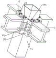
FIG. 1 is a schematic structural view of the present invention;
FIG. 2 is a schematic view of the attachment gusset mounting structure of the present invention;
FIG. 3 is a schematic view of the horizontal plane structure of the connecting steel column of the present invention;
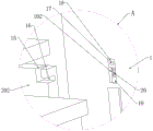
FIG. 4 is an enlarged view of the structure at A in FIG. 1 according to the present invention;
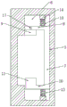
FIG. 5 is a schematic view of the internal structure of the rectangular frame according to the present invention;
fig. 6 is an enlarged view of the structure at B in fig. 2 according to the present invention.
In the figure: 1. connecting the steel columns; 101. connecting grooves; 102. a track groove; 2. an I-beam; 201. a horizontal plate; 202. a vertical plate; 3. connecting angle plates; 301. a U-shaped upper splice plate; 302. a U-shaped lower splice plate; 303. a connecting plate; 4. a rectangular frame; 5. a vertical slot; 6. a horizontal groove; 7. erecting a rod; 8. a first engagement rod; 9. a pin table; 10. a second engagement rod; 11. a wedge-shaped sliding table; 12. a first spring; 13. a second spring; 14. a first telescopic rod; 15. an L-shaped notch; 16. a rectangular notch; 17. a pressure lever; 18. pressing the cap; 19. a second telescopic rod; 20. a third spring; 21. a nut; 22. a gasket; 2201. and (5) saw teeth.
Detailed Description
The technical solution in the embodiments of the present invention will be clearly and completely described below with reference to the drawings in the embodiments of the present invention. It is obvious that the described embodiments are only a part of the embodiments of the present invention, and not all embodiments, and all other embodiments obtained by those skilled in the art without any inventive work are within the scope of the present invention.
In the description of the present invention, it should be noted that the terms "upper", "lower", "inner", "outer", "top/bottom", etc. indicate orientations or positional relationships based on orientations or positional relationships shown in the drawings, which are merely for convenience of description and simplification of description, but do not indicate or imply that the device or element referred to must have a specific orientation, be constructed and operated in a specific orientation, and thus, should not be construed as limiting the present invention. Furthermore, the terms "first" and "second" are used for descriptive purposes only and are not to be construed as indicating or implying relative importance.
In the description of the present invention, it should be noted that, unless otherwise explicitly specified or limited, the terms "mounted", "provided", "fitted/connected", "connected", and the like, are to be interpreted broadly, such as "connected", which may be fixedly connected, detachably connected, or integrally connected; can be mechanically or electrically connected; they may be connected directly or indirectly through intervening media, or they may be interconnected between two elements. The specific meanings of the above terms in the present invention can be understood in specific cases to those skilled in the art.
Examples
Referring to fig. 1-2, an energy-saving assembled steel frame structure includes: the connecting structure comprises connecting steel columns 1, I-shaped beams 2 and connecting angle plates 3.
Wherein, for the convenience of installation, the inside of connecting steel column 1 is hollow structure, has all seted up spread groove 101 on four faces of connecting steel column 1.
The I-shaped beam 2 comprises a pair of horizontal plates 201 and a vertical plate 202 vertically connected between the pair of horizontal plates 201, one end, close to the connecting steel column 1, of the vertical plate 202 is inserted into the connecting groove 101, and the pair of horizontal plates 201 and the connecting steel column 1 are tightly abutted after the vertical plate 202 is inserted into the connecting groove 101.
The four groups of connecting angle plates 3 are respectively welded on four outer surfaces of the connecting steel column 1, each group comprises a pair of connecting angle plates 3 with the same specification, openings of the pair of connecting angle plates 3 are oppositely arranged, any connecting angle plate 3 comprises a U-shaped upper splicing plate 301 and a U-shaped lower splicing plate 302, the U-shaped upper splicing plate 301 and the U-shaped lower splicing plate 302 are identical in specification, the inner diameters of the openings of the U-shaped upper splicing plate 301 and the U-shaped lower splicing plate 302 are identical to the thickness of the horizontal plate 201, sliding insertion of the pair of horizontal plates 201 is facilitated, the end portion of the I-shaped beam 2 is supported, and a connecting plate 303 is connected between the U-shaped upper splicing plate 301 and the U-shaped lower splicing plate 302.
Specifically, referring to fig. 3, a rectangular frame 4 is welded on the inner wall of a connecting steel column 1 to support an i-shaped beam 2 from inside, so that the i-shaped beam 2 is more stably installed, the rectangular frame 4 is communicated with a connecting groove 101 on the connecting steel column 1, a vertical groove 5 is formed in a vertical side wall on one side of the rectangular frame 4 along the extending direction of the side wall, horizontal grooves 6 are formed in horizontal side walls on the upper side and the lower side of the rectangular frame 4, and the vertical groove 5 on the rectangular frame 4 is connected with a pair of horizontal grooves 6;
a vertical rod 7 is connected in a vertical groove 5 on a rectangular frame 4 in a sliding mode, a first connecting rod 8 is horizontally connected to the upper end of the vertical rod 7, a pin platform 9 is installed on the lower end face of the first connecting rod 8, a second connecting rod 10 is horizontally connected to the lower end of the vertical rod 7, a wedge-shaped sliding table 11 is installed on the upper surface of the second connecting rod 10, when an I-shaped beam 2 is inserted into a connecting groove 101, the wedge-shaped sliding table 11 is pressed by the gravity of the I-shaped beam 2 to be gradually sunk into a horizontal groove 6 below, and the pin platform 9 is gradually exposed out of the horizontal groove 6 above until the pin platform is clamped on the I-shaped beam 2 and used for basic fixing.
Specifically, referring to fig. 5, in order to facilitate the timely return of the upright rod 7 during use, a first spring 12 is installed in the horizontal groove 6 below the rectangular frame 4, one end of the first spring 12, which is far away from the horizontal groove 6, is connected to a second connecting rod 10, a second spring 13 is installed in the horizontal groove 6 above the rectangular frame 4, and one end of the second spring 13, which is far away from the horizontal groove 6, is connected to the first connecting rod 8.
Specifically, referring to fig. 5, a first telescopic rod 14 is installed in each of the first spring 12 and the second spring 13, and the bottom of the first telescopic rod 14 is fixedly installed together with one side of the rectangular frame 4 located in the horizontal groove 6, so as to provide a guiding function for the vertical floating of the first spring 12 and the second spring 13.
Specifically, referring to fig. 5, in order to more stably mount the i-shaped beam 2 and the connecting steel column 1 together, an L-shaped notch 15 is formed in the upper surface of one end of the vertical plate 202 close to the connecting steel column 1, the length of a horizontal section of the L-shaped notch 15 is equal to the length of the first connecting rod 8, the length of a vertical section of the L-shaped notch 15 is equal to the bottom of the horizontal groove 6 from the second connecting rod 10 to the lower side, a rectangular notch 16 is formed in one surface of the vertical plate 202 close to the connecting steel column 1, and the rectangular notch 16 on the connecting steel column 1 is communicated with the L-shaped notch 15.
Specifically, referring to fig. 4 and 5, in order to facilitate the detachment of the i-shaped beam 2, a track groove 102 is formed above a connecting groove 101 on the connecting steel column 1, the track groove 102 is communicated with the horizontal groove 6, a pressure rod 17 is slidably installed in the track groove 102, one end of the pressure rod 17 is fixedly installed together with a first connecting rod 8, the other end of the pressure rod 17 is installed with a pressure cap 18, a second telescopic rod 19 is connected between the pressure cap 18 and the track groove 102 on the connecting steel column 1, a third spring 20 connected with the pressure cap 18 is installed at a movable end of the second telescopic rod 19, the pressure cap 18 is pressed downwards, the pressure cap 18 drives the first connecting rod 8 to move downwards continuously through the pressure rod 17, and at this time, the first connecting rod 8 and the pin block 9 pass through the rectangular notch 16, so that the i-shaped beam 2 is detached from the fixing of the pin block 9.
In particular, referring to FIG. 6, to install the gusset 3 with the I-beam 2. The U-shaped upper splicing plate 301, the U-shaped lower splicing plate 302 and the pair of horizontal plates 201 are connected through bolts, the bolts are connected with nuts 21 in a threaded mode, a pair of gaskets 22 with the same structure are coaxially mounted on the bolts between the nuts 21 and the U-shaped upper splicing plate 301, and the gaskets 22 are arranged to play a role in reinforcing stability.
Specifically, referring to fig. 6, the cam-shaped saw teeth 2201 of different specifications are arranged on the upper surface and the lower surface of the gasket 22, the density of the cam-shaped saw teeth 2201 on the contact surface of the gasket 22 and the adjacent external object is greater than that of the cam-shaped saw teeth 2201 on the contact surface of the gasket 22 and the gasket 22, so that the friction force between the gasket 22 and the adjacent external object is increased, the loss between the nut 21 and the U-shaped upper splice plate 301 is reduced, the cam-shaped saw teeth 2201 between the opposite surfaces of the pair of gaskets 22 are in wedge fit, and the convex inclination angle of the cam-shaped saw teeth 2201 on the opposite surfaces of the gasket 22 is greater than the thread pitch of the bolt.
The working principle is as follows:
when the I-shaped beam 2 slides into the connecting angle plate 3 until being inserted into the connecting groove 101, the wedge-shaped sliding table 11 is pressed by the gravity of the I-shaped beam 2 to be gradually sunk into the horizontal groove 6 below along with the gravity of the I-shaped beam 2, the pin table 9 is gradually exposed out of the horizontal groove 6 above and clamped in the L-shaped notch 15 on the I-shaped beam 2 for basic fixation, so that the vertical rod 7 can be reset in time during use, a first spring 12 is installed in the horizontal groove 6 below the rectangular frame 4, one end of the first spring 12, which is far away from the horizontal groove 6, is connected with a second connecting rod 10, a second spring 13 is installed in the horizontal groove 6 above the rectangular frame 4, and one end of the second spring 13, which is far away from the horizontal groove 6, is connected with the first connecting rod 8, so that quick installation and positioning can be conveniently realized;
during disassembly, a track groove 102 is formed above a connecting groove 101 in the connecting steel column 1, the track groove 102 is communicated with the horizontal groove 6, a pressing rod 17 is arranged in the track groove 102 in a sliding mode, one end of the pressing rod 17 is fixedly installed with the first connecting rod 8, a pressing cap 18 is installed at the other end of the pressing rod 17, a second telescopic rod 19 is connected between the pressing cap 18 and the track groove 102 in the connecting steel column 1, a third spring 20 connected with the pressing cap 18 is installed at the movable end of the second telescopic rod 19, the pressing cap 18 is pressed downwards, the pressing cap 18 drives the first connecting rod 8 to move downwards continuously through the pressing rod 17, at the moment, the first connecting rod 8 and the pin platform 9 penetrate through the rectangular notch 16, the I-shaped beam 2 is separated from the fixing of the pin platform 9, and quick disassembly is convenient to achieve.
Finally, it should be noted that: although the present invention has been described in detail with reference to the foregoing embodiments, it will be apparent to those skilled in the art that modifications may be made to the embodiments or portions thereof without departing from the spirit and scope of the invention.
Claims (7)
1. An energy-saving assembled steel body frame structure is characterized by comprising:
the connecting structure comprises a connecting steel column (1), wherein connecting grooves (101) are formed in four surfaces of the connecting steel column (1);
the I-shaped beam (2) comprises a pair of horizontal plates (201) and a vertical plate (202) vertically connected between the horizontal plates (201), and one end, close to the connecting steel column (1), of the vertical plate (202) is inserted into the connecting groove (101);
the steel column connecting structure comprises four groups of connecting angle plates (3), wherein the four groups of connecting angle plates (3) are respectively welded on four outer surfaces of a connecting steel column (1), any connecting angle plate (3) comprises a U-shaped upper splicing plate (301) and a U-shaped lower splicing plate (302), and a connecting plate (303) is connected between the U-shaped upper splicing plate (301) and the U-shaped lower splicing plate (302);
the steel column connecting structure is characterized in that a rectangular frame (4) is welded on the inner wall of the connecting steel column (1), the rectangular frame (4) is communicated with a connecting groove (101) in the connecting steel column (1), a vertical groove (5) is formed in the vertical side wall of one side of the rectangular frame (4) along the extending direction of the side wall, horizontal grooves (6) are formed in the horizontal side walls of the upper side and the lower side of the rectangular frame (4), and the vertical groove (5) in the rectangular frame (4) is connected with a pair of horizontal grooves (6);
vertical slot (5) sliding connection on rectangular frame (4) has pole setting (7), the upper end horizontally connected of pole setting (7) has first pole (8) that links up, round pin platform (9) are installed to the lower terminal surface of first pole (8) that links up, the lower extreme horizontally connected of pole setting (7) has second pole (10) that links up, the last surface mounting that the second linked up pole (10) has wedge slip table (11).
2. The energy-saving assembled steel body frame structure according to claim 1, wherein: install first spring (12) in horizontal groove (6) of rectangular frame (4) below, the one end and the second that horizontal groove (6) were kept away from in first spring (12) link together with second linking pole (10), install second spring (13) in horizontal groove (6) of rectangular frame (4) top, the one end and the first linking pole (8) that horizontal groove (6) were kept away from in second spring (13) link together.
3. The energy-saving assembled steel body frame structure according to claim 2, wherein: first telescopic links (14) are installed in the first spring (12) and the second spring (13), and the bottom of the first telescopic link (14) and one side of the rectangular frame (4) in the horizontal groove (6) are fixedly installed together.
4. An energy-saving assembled steel body frame structure according to claim 3, wherein: the steel column connecting structure is characterized in that an L-shaped notch (15) is formed in the upper surface of one end, close to the connecting steel column (1), of each vertical plate (202), the length of a horizontal section of each L-shaped notch (15) is equal to that of a first connecting rod (8), the length of a vertical section of each L-shaped notch (15) is equal to that of the bottom of a horizontal groove (6) from a second connecting rod (10) to the lower side, a rectangular notch (16) is formed in one side, close to the connecting steel column (1), of each vertical plate (202), and the rectangular notch (16) in the connecting steel column (1) is communicated with the L-shaped notch (15).
5. The energy-saving assembled steel body frame structure according to claim 4, wherein: a track groove (102) is formed in the upper portion of a connecting groove (101) in the connecting steel column (1), the track groove (102) is communicated with a horizontal groove (6), a pressing rod (17) is installed in the track groove (102) in a sliding mode, one end of the pressing rod (17) is fixedly installed with a first connecting rod (8), a pressing cap (18) is installed at the other end of the pressing rod (17), a second telescopic rod (19) is connected between the pressing cap (18) and the track groove (102) in the connecting steel column (1), and a third spring (20) connected with the pressing cap (18) is installed at the movable end of the second telescopic rod (19).
6. The energy-saving assembled steel body frame structure according to claim 5, wherein: splice plate (301) and splice plate (302) and a pair of horizontal plate (201) down pass through bolted connection on the U type, threaded connection has nut (21) on the bolt, is located coaxial arrangement has a pair of the same gasket (22) of structure on the bolt between splice plate (301) on nut (21) and the U type.
7. The energy-saving assembled steel body frame structure according to claim 6, wherein: the upper surface and the lower surface of the gasket (22) are provided with cam-shaped sawteeth (2201) with different specifications, the density of the cam-shaped sawteeth on the contact surface of the gasket (22) and an adjacent external object is greater than that of the cam-shaped sawteeth (2201) on the contact surface of the gasket (22) and the gasket (22), the cam-shaped sawteeth (2201) between the opposite surfaces of a pair of gaskets (22) are in wedge fit, and the convex surface inclination angle of the cam-shaped sawteeth (2201) on the opposite surfaces of the gasket (22) is greater than the thread pitch of the bolt.
Priority Applications (1)
| Application Number | Priority Date | Filing Date | Title |
|---|---|---|---|
| CN202111526157.4A CN114182820B (en) | 2021-12-15 | 2021-12-15 | Energy-saving assembly type steel body frame structure |
Applications Claiming Priority (1)
| Application Number | Priority Date | Filing Date | Title |
|---|---|---|---|
| CN202111526157.4A CN114182820B (en) | 2021-12-15 | 2021-12-15 | Energy-saving assembly type steel body frame structure |
Publications (2)
| Publication Number | Publication Date |
|---|---|
| CN114182820A CN114182820A (en) | 2022-03-15 |
| CN114182820B true CN114182820B (en) | 2023-03-24 |
Family
ID=80604903
Family Applications (1)
| Application Number | Title | Priority Date | Filing Date |
|---|---|---|---|
| CN202111526157.4A Active CN114182820B (en) | 2021-12-15 | 2021-12-15 | Energy-saving assembly type steel body frame structure |
Country Status (1)
| Country | Link |
|---|---|
| CN (1) | CN114182820B (en) |
Families Citing this family (2)
| Publication number | Priority date | Publication date | Assignee | Title |
|---|---|---|---|---|
| CN115262760B (en) * | 2022-08-18 | 2023-05-16 | 福建江夏学院 | An assembled steel pipe truss reinforced node connection structure and its application method |
| CN119593514B (en) * | 2024-12-02 | 2025-10-24 | 中国十七冶集团有限公司 | Beam-column connection node of assembled steel structure and its use method |
Family Cites Families (5)
| Publication number | Priority date | Publication date | Assignee | Title |
|---|---|---|---|---|
| CN207160238U (en) * | 2017-02-24 | 2018-03-30 | 新世界中国地产有限公司 | Prefabricated assembly type structure system |
| CN110080393B (en) * | 2019-05-14 | 2024-06-14 | 浙江大东吴集团建设有限公司 | Public building assembled steel structure |
| CN211257306U (en) * | 2019-11-14 | 2020-08-14 | 国网安徽众兴电力设计院有限公司 | A kind of wedge-shaped slot connecting assembled steel frame beam-column joint |
| CN212478345U (en) * | 2020-05-23 | 2021-02-05 | 苏州东尼建设发展有限公司 | Wall external corner mounting structure of wood veneer skeleton accessory formula installation |
| CN213014724U (en) * | 2020-07-06 | 2021-04-20 | 四川航天建筑工程有限公司 | A precast concrete beam and steel column connection structure |
-
2021
- 2021-12-15 CN CN202111526157.4A patent/CN114182820B/en active Active
Also Published As
| Publication number | Publication date |
|---|---|
| CN114182820A (en) | 2022-03-15 |
Similar Documents
| Publication | Publication Date | Title |
|---|---|---|
| CN114182820A (en) | Energy-saving assembly type steel body frame structure | |
| CN112112274B (en) | Assembly type steel structure building assembly and assembly method | |
| CN211572514U (en) | Scalable regulation outer wall scaffold frame | |
| CN221236205U (en) | Assembled connecting piece for steel structure building | |
| CN219261831U (en) | Steel truss web member structure | |
| CN219711104U (en) | Adjustable centering jacking of steel pipe scaffold | |
| CN216766203U (en) | Assembled beam column with bracing structure | |
| CN214144858U (en) | Steel structure support with reinforcing mechanism for building | |
| CN216740032U (en) | Connecting structure is assembled to steel house room | |
| CN223707261U (en) | A steel structure for substation towers | |
| CN223163786U (en) | Reinforcing apparatus suitable for bridge support node is ageing | |
| CN220117439U (en) | Steel structure connecting device | |
| CN224002177U (en) | Curtain stand coupling assembling | |
| CN222822539U (en) | A steel beam fixing structure | |
| CN216740367U (en) | Steel structure crossbeam for building engineering | |
| CN220014408U (en) | Support frame applied to heavy truss type support beam structure | |
| CN224016504U (en) | Combined assembly structure for arc beam | |
| CN223446350U (en) | Steel construction node convenient to assembly | |
| CN222413486U (en) | Assembled building connection piece | |
| CN111576625A (en) | Building steel structure connecting structure | |
| CN218989911U (en) | Cast-in-situ supporting structure of high-stability bridge | |
| CN220598741U (en) | Connecting device with waterproof and anti-corrosion functions for steel structure | |
| CN221118755U (en) | Steel frame structure for assembled building | |
| CN215166815U (en) | Building outer wall is with steel construction that shocks resistance | |
| CN222541648U (en) | Steel beam column of a factory building |
Legal Events
| Date | Code | Title | Description |
|---|---|---|---|
| PB01 | Publication | ||
| PB01 | Publication | ||
| SE01 | Entry into force of request for substantive examination | ||
| SE01 | Entry into force of request for substantive examination | ||
| GR01 | Patent grant | ||
| GR01 | Patent grant |