Disclosure of Invention
In view of the above, the invention discloses a single-port double-drinking cup, which realizes two drinking modes of direct drinking and drinking by a suction pipe by arranging a water diversion port.
The invention discloses a single-mouth double-drinking cup, which comprises a cup cover and a cup body, wherein the cup cover is connected with the cup body and is connected with a straw through a straw hole;
the connecting portion are close to the position of water inlet portion is provided with the inlet opening, the portion of absorbing water can drive the inlet opening stretches into or stretches out the straw hole, be provided with water sealing spare on the lateral wall in straw hole, water sealing spare is to stretching into the straw hole the inlet opening is sealed.
Further, the cup cover comprises a bottom cover and a top cover, the bottom cover is detachably connected with the cup body, and the straw hole is formed in the bottom cover; the top cover is hinged with the bottom cover and used for opening or sealing the drinking mouth.
Furthermore, a water sealing plug is arranged on the top cover, and the drinking water port is sealed through the water sealing plug.
Furthermore, a telescopic groove is formed in the bottom cover, one end of the water absorbing part extends into the telescopic groove and is connected with the connecting part, and the water absorbing part can move telescopically relative to the telescopic groove.
Further, it includes first sealing, the second is sealed and the third sealing to seal water spare, first sealing laminate in the inner wall of straw hole, and pass through the second sealing with the third sealing is fixed, the laminating of second sealing the bottom surface of straw hole, flexible groove passes through the second sealing prevents the water absorption portion stretches into in the straw hole.
Furthermore, one end of the connecting part and the water absorbing part are integrally formed, and the other end of the connecting part is connected with the water inlet part through a connecting piece and prevents the water inlet part from extending into the straw hole through the connecting piece.
Furthermore, one side of the top cover is rotatably connected with the bottom cover through a rotating shaft, and an elastic reset piece for driving the top cover to reset is arranged on the rotating shaft; the other side of the top cover is connected with the bottom cover through a locking mechanism.
Further, locking mechanism includes the locking plate, the locking plate with bottom normal running fit, the one end of locking plate is provided with first locking portion, be provided with on the top cap with first locking portion complex second locking portion, the locking plate with be provided with the drive between the bottom the locking spring that the locking plate resets.
Furthermore, a locking ring is rotatably connected to the bottom cover, a third locking portion matched with the locking ring is arranged on the top cover, and the locking ring locks the top cover through the third locking portion.
Furthermore, a hollow-out part is arranged on the connecting part and comprises a plurality of water inlets.
Compared with the prior art, the technical scheme disclosed by the invention has the beneficial effects that:
when the suction pipe is required to suck water, the water inlet hole extends into the suction pipe hole and is sealed through the water sealing part, the water sucking part and the water inlet part are in sealing fit at the moment, and water in the cup body is sucked through the water inlet part;
when direct drinking water is needed, the water inlet hole extends out of the straw hole, the cup body is taken, so that water in the cup body enters the straw through the water inlet hole, and direct drinking water is conducted through the water diversion port at the moment.
Detailed Description
When one component is considered to be "connected" to another component, it can be directly connected to the other component, or intervening components may be present. Unless defined otherwise, all technical and scientific terms used herein have the same meaning as commonly understood by one of ordinary skill in the art to which this invention belongs. It should also be noted that, unless expressly stated or limited otherwise, the terms "mounted," "connected," and "connected" are to be construed broadly and can include, for example, fixed connections, removable connections, or integral connections; either mechanically or electrically, and may be internal to both elements. The specific meanings of the above terms in the present invention can be understood in specific cases to those skilled in the art. The terminology used in the description of the invention herein is for the purpose of describing particular embodiments only and is not intended to be limiting of the invention.
It should be noted that in the description of the present invention, it should be noted that the terms "center", "upper", "lower", "left", "right", "vertical", "horizontal", "inner", "outer", etc. indicate orientations or positional relationships based on the orientations or positional relationships shown in the drawings, which are only for convenience of describing the present invention and simplifying the description, but do not indicate or imply that the referred device or element must have a specific orientation, be configured in a specific orientation, and operate, and thus, should not be construed as limiting the present invention. Furthermore, the terms "first," "second," and "third" are used for descriptive purposes only and are not to be construed as indicating or implying relative importance.
As shown in figures 1 and 2, the invention discloses a single-mouth double-drinking cup 100, which comprises a cup cover 10, a cup body 20 and a straw 30, wherein the cup cover 10 is detachably connected with the cup body 20, one end of the straw 30 is positioned in the cup body 20, the other end of the straw 30 penetrates through the cup cover 10, one end of the straw 30 penetrating through the cup cover 10 is provided with a drinking water mouth 31, and water in the cup body 20 can be directly drunk through the drinking water mouth 31 or can be sucked through the straw 30.
The cup cover 10 comprises a bottom cover 11 and a top cover 12, the bottom cover 11 is detachably connected with the cup body 20, a straw hole 112 is formed in the bottom cover 11, one end, provided with the drinking water port 31, of the straw 30 penetrates through the bottom cover 11 through the straw hole 112, and the top cover 12 is connected with the bottom cover 11 and can open or seal the drinking water port 31.
Specifically, the bottom cover 11 is detachably connected with the cup body 20, and seals an opening at the top end of the cup body 20, a thread groove is formed in the bottom cover 11, a sealing gasket 111 is arranged in the thread groove, the top end of the cup body 20 extends into the thread groove and is in threaded connection with the thread groove, the top end of the cup body 20 abuts against the sealing gasket 111, and the bottom cover 11 and the cup body 20 are in sealing fit.
The sealing gasket 111 is made of a silicone material.
Further, the bottom cover 11 on one side of the top cover 12 is hinged, the other side of the top cover 12 can be locked or unlocked with the bottom cover 11 through a locking mechanism 40, a water sealing plug 121 is arranged on the top cover 12, and when the top cover 12 is locked with the bottom cover 11 through the locking mechanism 40, the water sealing plug 121 abuts against the drinking opening 31 on the suction pipe 30 to seal the drinking opening 31; after the top cover 12 and the bottom cover 11 are unlocked, the water sealing plug 121 does not abut against the drinking water port 31 any more, and at this time, the drinking water port 31 is opened, so that drinking water can be carried out through the drinking water port 31.
Furthermore, one side of the top cover 12 is rotatably connected to the bottom cover 11 through a rotating shaft 14, and an elastic reset member is matched on the rotating shaft 14, when the top cover 12 and the bottom cover 11 are locked by the locking mechanism 40, the elastic reset member applies an elastic force to the top cover 12 to enable the top cover 12 to rotate towards a direction tending to open the drinking water port 31, and when the locking mechanism 40 does not lock the top cover 12 any more, the elastic reset member drives the top cover 12 to rotate around the rotating shaft 14 to open the drinking water port 31.
In this application, the elastic reset piece is a torsion spring.
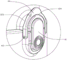
With reference to fig. 3, further, the locking mechanism 40 includes a locking plate 41, the locking plate 41 is rotatably connected to the bottom cover 11, a first locking portion 411 is disposed at one end of the locking plate 41, a second locking portion 122 engaged with the first locking portion 411 is disposed on the top cover 12, and a locking spring 42 for driving the locking plate 41 to reset is disposed between the locking plate 41 and the bottom cover 11. When the water drinking device is locked, the top cover 12 rotates around the rotating shaft 14 for a certain angle, so that the top cover 12 seals the water drinking opening 31, and the first locking part 411 is matched with the second locking part 122 to lock the top cover 12; when needing the unblock, press locking plate 41 is kept away from the one end of first locking portion 411, the compression locking spring 42 makes simultaneously locking plate 41 is provided with the one end perk of first locking portion 411 and with second locking portion 122 separates, and it is no longer right this moment top cap 12 carries out the locking, top cap 12 is in rotatory the reseing under the effect that elasticity resets, opens drinking water mouth 31.
In this application, the first locking portion 411 is a locking groove, the second locking portion 122 is a locking protrusion, and when the locking protrusion extends into the locking groove, the locking mechanism 40 locks the top cover 12.
As shown in fig. 4, the locking mechanism 40 further includes a locking ring 44, a third locking portion 123 cooperating with the locking ring 44 is provided on the top cover 12, and the locking ring 44 locks the top cover 12 through the third locking portion 123. When the first locking portion 411 is engaged with the second locking portion 122, the locking ring 44 is rotated to engage the locking ring 44 with the third locking portion 123, so as to further lock the top cover 12 and prevent the drinking spout 31 from being opened without being touched. Specifically, the locking plate 41 is rotatably connected to the bottom cover 11 by a connecting shaft 43, and the locking ring 44 is located outside the locking plate 41 and is also rotatably engaged with the connecting shaft 43. The third locking part 123 is provided with a stopper protrusion 124 corresponding to the locking ring 44, and the locking ring 44 can be engaged with the third locking part 123 or disengaged from the third locking part 123 when a certain external force is applied to the locking ring 44.
Furthermore, a drinking hole 31 of the drinking straw 30 is located in the housing formed when the top cover 12 and the bottom cover 11 are locked, and one end of the drinking straw 30 far away from the drinking hole 31 extends into the cup body 20.
Further, the suction pipe 30 includes a water absorption portion 32, a water inlet portion 33 and a connection portion 34, wherein the water inlet portion 33 is located in the cup body 20, the drinking water port 31 is located at an end of the water absorption portion 32 away from the water inlet portion 33, the water absorption portion 32 is communicated with the water inlet portion 33 through the connection portion 34, the water absorption portion 32, the water inlet portion 33 and the connection portion 34 are completely conducted to enable water absorption, and an end of the water inlet portion 33 away from the water absorption portion 32 can extend to a bottom end of the cup body 20. The water absorption part 32 and the water inlet part 33 are respectively located at two sides of the straw hole 112, the connecting part 34 penetrates through the straw hole 112, two ends of the connecting part 34 are respectively connected with the water absorption part 32 and the water inlet part 33, and the connecting part 34 can do telescopic motion relative to the straw hole 112. In the present application, the external force applied to the water absorbing portion 32 can drive the connecting portion 34 to perform a telescopic motion relative to the straw hole 112.
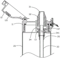
As shown in fig. 5 and 6, a water inlet 341 is disposed at a position of the connection part 34 close to the water inlet 33, and when the connection part 34 makes a telescopic motion relative to the straw hole 112, the water inlet 341 can extend into or out of the straw hole 112. Further, a water sealing member 13 is disposed on a side wall of the straw hole 112, and when the water inlet 341 enters the straw hole 112, the water sealing member 13 is attached to an outer wall of the connecting portion 34 to seal the water inlet 341. The water sealing member 13 is tightly fitted with the connecting portion 34, when the water inlet 341 enters the straw hole 112, the water sealing member 13 can seal the straw hole 112, and when a certain external force is applied to the water absorbing portion 32, the connecting portion 34 can be driven to perform telescopic motion relative to the straw hole 112, so that the water inlet 341 enters or leaves the straw hole 112.
Further, a hollow portion is disposed on the connecting portion 34, and the hollow portion is provided with a plurality of water inlets 341.
In the present application, the suction pipe 30 and the water sealing member 13 are both made of a silicone material.
As shown in fig. 6, when water in the cup body 20 needs to be sucked by the drinking straw 30, the connecting portion 34 is pulled by the water sucking portion 32, so that the water inlet 341 leaves the cup body 20 and enters the drinking straw hole 112, the water sealing member 13 seals the water inlet 341 in the drinking straw hole 112, and the drinking straw 30 forms a tube body with only two ends being conducted, so that a user can suck water in the cup body 20 through the drinking straw 30 at the drinking water port 31;
as shown in fig. 7, when the water in the cup body 20 needs to be drunk directly, the connecting part 34 is pushed by the water sucking part 32 to move relative to the straw hole 112, so that the water inlet 341 leaves the straw hole 112 and enters the cup body 20, the water inlet 341 is located at the top end of the cup body 20, the drinking water port 31 can be communicated with the inner space of the cup body 20 through the water inlet 341, when drinking, a user takes the cup body 20 and tilts the cup body 20, the water can flow to the top end of the cup body 20 and is located at the periphery of the water inlet 341, and the water can enter the drinking water pipe 30 through the water inlet 341 and flow out of the drinking water port 31 along the drinking water pipe 30.
Through right inlet opening 341 seals or opens, realizes through drinking water mouth 31 carries out straw formula drinking water or directly drinks formula drinking water two kinds of modes, simple structure need not set up unnecessary drinking water mouth 31 to reduce the structure assembly of different drinking water modes, simple structure reduces design cost and processing cost.
As shown in fig. 5 and 8, a telescopic slot 113 is further disposed on the bottom cover 11, one end of the water absorbing part 32 extends into the telescopic slot 113 to connect with the connecting part 34, and the water absorbing part 32 can move telescopically relative to the telescopic slot 113. Specifically, the one end that water absorption portion 32 kept away from water inlet portion 33 stretches out telescopic groove 113, the other end of water absorption portion 32 stretches into telescopic groove 113 in-connection connecting portion 34's one end, when through water absorption portion 32 drives connecting portion 34 is relative when suction tube hole 112 is concertina movement, water absorption portion 32 can be relative simultaneously telescopic groove 113 is concertina movement. The water absorption part 32 is provided with a guide protrusion 321, a guide groove 114 matched with the guide protrusion 321 is arranged in the telescopic groove 113, and the water absorption part 32 slides along the guide groove 114 through the guide protrusion 321.
Further, the water sealing member 13 includes a first sealing portion 131, a second sealing portion 132 and a third sealing portion 133, the first sealing portion 131 is attached to the inner wall of the straw hole 112, and when the water inlet hole 341 extends into the straw hole 112, the first sealing portion 131 seals the water inlet hole 341. The second sealing portion 132 and the third sealing portion 133 are respectively disposed at two ends of the first sealing portion 131, the first sealing portion 131 is fixed by the second sealing portion 132 and the third sealing portion 133, specifically, the second sealing portion 132 is located in the telescopic groove 113 and attached to the bottom end of the telescopic groove 113, and the third sealing portion 133 is located below the bottom cover 11 and attached to the bottom end of the bottom cover 11.
The diameter of the water absorbing part 32 is greater than that of the connecting part 34, the diameter of the telescopic groove 113 is greater than that of the straw hole 112, when the water absorbing part 32 extends into the telescopic groove 113 for a certain distance, the second sealing part 132 stops the water absorbing part 32 from extending into the straw hole 112, and at the moment, the water inlet 341 extends out of the straw hole 112 and enters the cup body 20.
Further, one end of the connecting portion 34 is integrally formed with the water absorbing portion 32, and the other end is connected to the water inlet portion 33 through a connecting member 35, and the water inlet portion 33 is prevented from extending into the straw hole 112 by the connecting member 35. Specifically, the water inlet part 33 is fixedly connected with the connecting part 35, and one end of the connecting part 34 far away from the water absorbing part 32 extends into the connecting part 35 and is in threaded connection with the connecting part 35, so that the water inlet part 33 is communicated with the connecting part 34. The diameter of the connecting member 35 is larger than that of the straw hole 112, and when the connecting member 34 extends into the straw hole 112, the connecting member 35 abuts against the bottom cover 11 to prevent the water inlet portion 33 from extending into the straw hole 112.
The present invention may be embodied in many different forms and modifications without departing from the spirit and scope of the present invention, and the above-described embodiments are intended to illustrate the present invention but not to limit the scope of the present invention.