Disclosure of Invention
Aiming at the problems in the prior art, the invention provides an electric shock prevention double protection constant current source rectification circuit, which comprises:
the input end of the power port is connected with commercial power, the output end of the power port is connected with the input end of a first protection module, the first protection module comprises a fuse, one end of the fuse is connected with the output end of the power port, the other end of the fuse is connected with three series resistors, and when the output current of the power port is larger than the fusing value of the fuse, the fuse controls the circuit to be disconnected; and
when the circuit is powered off, the electric quantity stored by the circuit is discharged through the three series resistors so as to perform first protection on the circuit;
the input end of the second protection module is connected with the output end of the first protection module, the second protection module comprises a thermistor, one end of the thermistor is connected with the output end of the first protection module, and when the circuit is conducted, surge current is reduced through the thermistor so as to carry out second protection on the circuit;
the input end of the rectification output module is connected with the output end of the second protection module, the output end of the rectification output module is connected with an external device, and the rectification output module rectifies the output voltage of the second protection module and supplies power for the external device.
Preferably, the output end of the power port is connected to the input end of the first protection module through a live wire and a zero wire, and is grounded through a ground wire.
Preferably, the first protection module includes:
one end of the piezoresistor is connected with the other end of the fuse, the other end of the piezoresistor is connected with the zero line, and the output voltage of the power supply port is clamped at a fixed value through the piezoresistor so as to perform overvoltage protection on the circuit;
the input end of the first inductor is respectively connected with the two ends of the piezoresistor, and the output end of the first inductor is connected with the input end of the second protection module;
one end of the fuse and the other end of the piezoresistor are used as input ends of the first protection module, and the output end of the first inductor is used as the output end of the first protection module;
the fuse controls to disconnect the circuit to protect the first inductor when the output current of the power supply port is larger than the fusing value of the fuse.
Preferably, the first inductor is a common mode inductor.
Preferably, the first protection module further includes:
the two ends of the first capacitor are respectively connected with the output end of the first inductor;
one end of the first resistor is respectively connected with one end of the first capacitor and the output end of the first inductor;
one end of the second resistor is connected with the other end of the first resistor;
one end of the third resistor is connected with the other end of the second resistor, and the other end of the third resistor is respectively connected with the other end of the first capacitor and the output end of the first inductor;
when the circuit is powered off, the electric quantity stored by the first capacitor is discharged through the first resistor, the second resistor and the third resistor so as to protect the first inductor.
Preferably, the first capacitor is a safety capacitor.
Preferably, the second protection module includes:
the input end of the second inductor is respectively connected with the output end of the first protection module and the other end of the thermistor;
one end of the third inductor is connected with the output end of the second inductor, and the other end of the third inductor is connected with the output end of the rectification output module;
the fourth resistor is connected in parallel with two ends of the third inductor, and when the circuit is powered off, the large current generated on the third inductor is discharged through the fourth resistor so as to protect the rectification output module;
the input end of the second inductor is used as the input end of the second protection module, and the other end of the third inductor is used as the output end of the second protection module;
when the circuit is short-circuited, the thermistor controls to open the circuit to protect the second inductor.
Preferably, the second inductor is a common mode inductor, and the third inductor is a differential mode inductor.
Preferably, the rectification output module includes:
a first interface of the rectifier bridge is connected with the output end of the second protection module, a second interface of the rectifier bridge is connected with an anode port, a third interface of the rectifier bridge is connected with the output end of the second inductor, and a fourth port of the rectifier bridge is connected with a cathode port;
one end of the second capacitor is connected with the second interface of the rectifier bridge and the positive electrode port respectively, and the other end of the second capacitor is connected with the fourth interface of the rectifier bridge and the negative electrode port respectively;
one end of the third capacitor is connected with a third interface of the rectifier bridge and the output end of the second inductor respectively, and the other end of the third capacitor is grounded;
the fourth capacitor is connected in parallel with two ends of the second capacitor;
one end of the fifth capacitor is connected with the negative electrode port, the other end of the second capacitor and one end of the fourth capacitor respectively, and the other end of the fifth capacitor is grounded;
the first interface and the third interface of the rectifier bridge are used as the input end of the rectifier output module, and the positive electrode port and the negative electrode port are used as the output end of the rectifier output module;
the output voltage of the second protection module is rectified through the rectifier bridge to obtain rectified voltage, the rectified voltage is filtered through the second capacitor and the fourth capacitor to obtain filtered voltage, and the filtered voltage is output through the positive port and the negative port.
Preferably, the third capacitor and the fifth capacitor are safety capacitors.
The technical scheme has the following advantages or beneficial effects: this circuit realizes anticreep duplicate protection through first protection module and second point protection module, can satisfy overheat protection, overvoltage protection, short-circuit protection and shutdown protection simultaneously, can effectively prevent the emergence of electric shock incident.
Detailed Description
The invention is described in detail below with reference to the figures and specific embodiments. The present invention is not limited to the embodiment, and other embodiments may be included in the scope of the present invention as long as the gist of the present invention is satisfied.
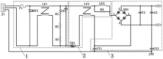
In the preferred embodiment of the present invention, based on the above problems in the prior art, there is provided an anti-electric shock dual protection constant current source rectification circuit, as shown in fig. 1, including:
the power supply port J1 is connected with the input end of the power supply port J1, the output end of the power supply port J1 is connected with the input end of a first protection module 1, the first protection module 1 comprises a fuse F1, one end of the fuse F1 is connected with the output end of the power supply port J1, the other end of the fuse F1 is connected with three series resistors, and when the output current of the power supply port J1 is larger than the fusing value of the fuse F1, the fuse F1 control circuit is disconnected; and
when the circuit is powered off, the electric quantity stored by the circuit is discharged through the three series resistors so as to perform first protection on the circuit;
the input end of the second protection module 2 is connected with the output end of the first protection module 1, the second protection module 2 comprises a thermistor TR1, one end of the thermistor TR1 is connected with the output end of the first protection module 1, and when the circuit is conducted, surge current is reduced through the thermistor TR1 so as to carry out second protection on the circuit;
and the input end of the rectification output module 3 is connected with the output end of the second protection module 2, the output end of the rectification output module 3 is connected with an external device, and the output voltage of the second protection module 2 is rectified through the rectification output module 3 and is supplied for the external device.
Specifically, in this embodiment, when the thermistor TR1 is in a cold state and the circuit is turned on, the inrush current can be reduced, and after normal operation, the temperature of the thermistor TR1 rises, the resistance value is reduced, and the power consumption of the circuit is reduced.
In the preferred embodiment of the present invention, the output terminal of the power port J1 is connected to the input terminal of the first protection module 1 through a live wire and a neutral wire, and is grounded through a ground wire.
In a preferred embodiment of the present invention, the first protection module 1 comprises:
one end of a piezoresistor MOV1, one end of a piezoresistor MOV1 is connected with the other end of the fuse F1, the other end of the piezoresistor MOV1 is connected with a zero line, and the output voltage of the power port J1 is clamped at a fixed value through the piezoresistor MOV1 so as to perform overvoltage protection on the circuit;
the input end of the first inductor LF1 is respectively connected with the two ends of the varistor MOV1, and the output end of the first inductor LF1 is connected with the input end of the second protection module 2;
one end of the fuse F1 and the other end of the piezoresistor MOV1 are used as input ends of the first protection module 1, and the output end of the first inductor LF1 is used as an output end of the first protection module 1;
the fuse F1 controls the open circuit to protect the first inductor LF1 when the output current of the power port J1 is greater than its fusing value.
Specifically, the voltage dependent resistor MOV1 is used to protect the circuit from overvoltage, and when the input voltage appears between the two poles of the voltage dependent resistor MOV1, the voltage dependent resistor MOV1 can clamp the input voltage to a relatively fixed voltage value, thereby protecting the circuit.
In the preferred embodiment of the present invention, the first inductor LF1 is a common mode inductor.
In a preferred embodiment of the present invention, the first protection module 1 further includes:
two ends of the first capacitor CX1 are respectively connected with the output end of the first inductor LF 1;
one end of the first resistor R1 is connected to one end of the first capacitor CX1 and the output end of the first inductor LF1 respectively;
one end of the second resistor R2 is connected with the other end of the first resistor R1;
one end of the third resistor R3 is connected to the other end of the second resistor R2, and the other end of the third resistor R3 is connected to the other end of the first capacitor CX1 and the output end of the first inductor LF 1;
when the circuit is powered off, the stored electric quantity of the first capacitor CX1 is discharged through the first resistor CX1, the second resistor CX2 and the third resistor CX3 so as to protect the first inductor LF 1.
Specifically, in this embodiment, the first capacitor CX1 is connected in parallel to the first resistor R1, the second resistor R2 and the third resistor R3, and is configured to discharge the electric quantity stored in the first capacitor CX1 to the first resistor R1, the second resistor R2 and the third resistor R3 after the power failure occurs, so as to prevent the user from accidentally touching the electric shock hazard.
In a preferred embodiment of the present invention, the first capacitor CX1 is a safety capacitor.
Specifically, in this embodiment, the first capacitor CX1 is an X-type safety capacitor.
In a preferred embodiment of the present invention, the second protection module 2 comprises:
the input end of the second inductor LF2 is connected with the output end of the first protection module 1;
one end of the third inductor LF3 is connected to the output end of the second inductor LF2, and the other end of the third inductor LF3 is connected to the output end of the rectification output module 3;
the fourth resistor R4 and the fourth resistor R4 are connected in parallel with two ends of the third inductor LF3, and when the circuit is powered off, the large current generated on the third inductor LF3 is discharged through the fourth resistor R4 so as to protect the rectification output module 3;
the input end of the second inductor LF2 is used as the input end of the second protection module 2, and the other end of the third inductor LF3 is used as the output end of the second protection module 2;
when the circuit is short-circuited, the thermistor TR1 controls to open the circuit to protect the second inductor LF 2.
Specifically, in the embodiment, the circuit is short-circuit protected by the thermistor TR1, and when the temperature of the thermistor TR1 exceeds the self temperature limit value due to the short circuit of the circuit, the circuit is disconnected, and the voltage input is stopped.
In a preferred embodiment of the present invention, the second inductor LF2 is a common mode inductor, and the third inductor LF3 is a differential mode inductor.
Specifically, in the present embodiment, the common mode inductor LF1 and the common mode inductor LF2 are used in the circuit to remove high frequency interference and low frequency interference during voltage transmission, and the differential mode inductor LF3 is used to remove interference signals.
In a preferred embodiment of the present invention, the rectification output module 3 includes:
a rectifier bridge BD1, a first interface of the rectifier bridge BD1 is connected with the output end of the second protection module 2, a second interface of the rectifier bridge BD1 is connected with a positive electrode port V +, a third interface of the rectifier bridge BD1 is connected with the output end of the second inductor LF2, and a fourth port of the rectifier bridge BD1 is connected with a negative electrode port V-;
one end of the second capacitor C1 is connected with a second interface and a positive electrode port V & lt- & gt of the rectifier bridge BD1, and the other end of the second capacitor C1 is connected with a fourth interface and a negative electrode port V & lt- & gt of the rectifier bridge BD 1;
one end of a third capacitor CY1, one end of the third capacitor CY1 being respectively connected to the third interface of the rectifier bridge BD1 and the output end of the second inductor LF2, the other end of the third capacitor CY1 being grounded;
a fourth capacitor C2, the fourth capacitor C2 is connected in parallel to two ends of the second capacitor C1;
one end of a fifth capacitor CY2 is connected with the negative electrode port V-, the other end of the second capacitor C1 and one end of a fourth capacitor C2 respectively, and the other end of the fifth capacitor CY2 is grounded;
a first interface and a third interface of the rectifier bridge BD1 are used as input ends of the rectifier output module 3, and a positive electrode port V + and a negative electrode port V-are used as output ends of the rectifier output module 3;
the output voltage of the second protection module 2 is rectified through the rectifier bridge BD1 to obtain rectified voltage, the rectified voltage is filtered through the second capacitor C1 and the fourth capacitor C2 to obtain filtered voltage, and the filtered voltage is output through the positive port V + and the negative port V-.
Specifically, in the present embodiment, the third inductor LF3 is connected in parallel with the fourth resistor R4 to prevent a large current on the third inductor LF3 from breaking through the rectifier bridge BD1 when the power supply is powered off.
Specifically, in this embodiment, the second capacitor C1 and the fourth capacitor C2 are filter capacitors, and the voltage rectified by the rectifier bridge BD1 is filtered by the second capacitor C1 and the fourth capacitor C2 and is transmitted to the positive terminal V + and the negative terminal V-for output.
In the preferred embodiment of the present invention, the third capacitor CY1 and the fifth capacitor CY2 are safety capacitors.
Specifically, in this embodiment, the circuit adopts two Y-type safety capacitors, namely, a third capacitor CY1 and a fifth capacitor CY2, which are respectively disposed between the ground line and the zero line before rectification and between the ground line and the negative terminal V-after rectification, so that the circuit is more stable and reliable.
While the invention has been described with reference to a preferred embodiment, it will be understood by those skilled in the art that various changes in form and detail may be made therein without departing from the spirit and scope of the invention.