Detachable lamp and assembling method
Technical Field
The invention relates to the technical field of illumination, in particular to a detachable lamp and an assembling method.
Background
Linear lamps are used for local illumination; the existing linear lamp is arranged in an integrated manner; the size of the linear lamp is fixed; it is not possible to lengthen or shorten the length of the linear lamp according to the lighting requirements; is inconvenient to use.
In chinese patent application No. 201910054553.8; patent application No. 2019.01.21 discloses a light string that is easy to disassemble; including power adapter and be connected and concatenate the lamp cluster group that forms by a plurality of lamp bodies with power adapter, can dismantle between lamp body and the lamp body and be connected, every the lamp body includes the main part, connects the first interface in the main part and sets up and connect the second that pegs graft in counterpoint with the first in the main part and connect, connects through first joint and second articulate between two adjacent lamp bodies, and the lamp body connects in power adapter through first joint detachable.
However, in the light string, the first connector is connected with the main body through the power line, and when the light string is installed, one end of the main body, which is connected with the first connector, needs to be aligned with one end of the other main body, which is provided with the second connector; the installation of the lamp body has directivity; is inconvenient to use; meanwhile, in order to make the input voltage consistent with the working voltage of the lamp body, the lamp string supplies power to the lamp body after the voltage is reduced by the power adapter; the lamp string does not consider that if the power adapter with higher output voltage is misused, the output voltage of the power adapter is higher than the working voltage of the lamp body, and the lamp body can be damaged.
Disclosure of Invention
The invention provides a detachable lamp and an assembly method, wherein a controller is conveniently and stably connected with lamp bodies and adjacent lamp bodies, and meanwhile, the controller can control the on, off and brightness of a lighting lamp.
In order to achieve the purpose, the technical scheme of the invention is as follows: a detachable light comprising a lighting device; forming a concave groove at the corners of the upper and lower sides of the back surface of the lighting device; the lighting device comprises a controller and more than one lamp body; the adjacent lamp bodies and the controller are detachably connected with the lamp bodies; the end parts of the controller and the lamp body are provided with plug connectors; the plug connector comprises a base body and a plug part; one end of the seat body is connected with one end of the insertion part; the other end of the inserting part is connected with a first interface and covers the outer surface of the first interface; the base body is provided with a groove sunken towards the inserting part; the groove is communicated with the first interface; the connector comprises a first connecting part, a second connecting part and two second interfaces; the first connecting part is connected with the second connecting part and is positioned between the two second interfaces; the first connecting part is connected with one second interface, and the second connecting part is connected with the other second interface; the first connecting part and the second connecting part are respectively inserted into the grooves of the adjacent plug connectors, and the second interface penetrates through the grooves to be connected with the first interface; an input interface is arranged on one side of the controller; the first interface, the second interface and the input interface are all Type-c interfaces; the first interface, the second interface and the input interface all use less than eight pins; the controller comprises a voltage reduction circuit, a human body induction circuit, a gesture control circuit, an illumination detection circuit and an output circuit, wherein the voltage reduction circuit supplies power to the human body induction circuit, the gesture control circuit, the illumination detection circuit and the output circuit, and the human body induction circuit, the gesture control circuit and the illumination detection circuit respectively control the lighting device through the output circuit.
In the arrangement, more than one first interface is arranged on both the controller and the lamp body; the first interface is connected with the connector; the controller is detachably connected with more than one lamp body; the controller and the lamp body use the same first interface; when the lamp is installed and used, only one end of the controller needs to be aligned with one end of the lamp body; then the controller and the lamp body are connected through the connector; the orientation of the end part of the lamp body does not need to be considered during installation; the use is convenient; meanwhile, the controller can be connected with different end parts of the lamp body; when a plurality of lamp bodies need to be installed for use; only the other lamp body is electrically connected with the lamp body or the controller through the connector; the number of the lamp bodies and the position relation between the controller and the lamp bodies can be set according to the use scene; the use scene is extensive. Meanwhile, the first interface, the second interface and the input interface all use less than eight pins; when in use, the lamp body is powered through the connector matched with the input interface; the input voltage is prevented from being higher than the working voltage of the lamp body, so that the lamp body is prevented from being damaged; meanwhile, the connector needs to be matched with an input interface for use; the power supply of other electrical products by using the connector can be avoided; the input voltage of the connector is higher than the working voltage of other electric appliance products, and other electric appliances are damaged.
The sunken groove extends along the length direction of lamp body and forms and link up the groove, and this structure, when installation lamps and lanterns, the area at the lamps and lanterns back reduces, lets the contact installation thing that lamps and lanterns can be better, simultaneously, sets up the sunken groove back in the upper and lower both sides at the back, and when installation lamps and lanterns, operating personnel's hand can grab lamps and lanterns and be difficult to the slippage, and the installation is all reliable with the dismantlement.
Because the controller with the voltage reduction circuit, the human body induction circuit, the gesture control circuit, the illumination detection circuit and the output circuit is arranged, the lighting lamp can be controlled to be turned on, turned off, lightened and the like through human body induction, gesture induction, illumination induction and the like, the control is convenient, and the energy-saving effect is good.
Further, the connector is a rigid connector; the first connecting part and the second connecting part are integrally arranged; the adjacent plug connectors are tightly attached; the first connecting portion and the second connecting portion are hidden between the adjacent plug connectors.
According to the arrangement, the adjacent plug connectors are tightly attached; when the controller is connected with the lamp body and the lamp body is connected with the lamp body; the controller is tightly attached to the lamp body and the lamp body is tightly attached to the lamp body; shielding the rigid connector; the rigid connector is not exposed outside; the appearance is beautiful; meanwhile, when the controller is connected with the lamp body and the lamp body is connected with the lamp body; the rigid connecting part is inserted into the groove; the rigid connecting part provides a supporting force for the adjacent plug connector; the rigid connecting part plays a supporting role at the connecting part of the controller and the lamp body and the connecting part of the lamp body and the lamp body; this enables stable use of the detachable lamp.
Further, the connector is a flexible connector; the connector further comprises a flexible connector; first connecting portion and the split type setting of second connecting portion, flexible connection connects between first connecting portion and second connecting portion.
Through the arrangement, the flexible connecting piece is arranged, so that one second interface can move relative to the other second interface.
Furthermore, the positive pins of the first interface, the second interface and the input interface are all ends A1, B1, A12 and B12; the negative pins of the first interface, the second interface and the input interface are all ends A4, B5, A9 and B9.
In the arrangement, the positions of the positive electrode pin and the repolarization pin are arranged; the lamp body is powered through the connector matched with the input interface.
Further, the cross section of the concave groove is arc-shaped.
Above setting, beautify the outward appearance structure of lamps and lanterns on the one hand, solve the technical problem who snatchs simultaneously.
Further, the lamp body further comprises an LED light source, a light guide plate and a diffusion plate; first mounting grooves are formed in two sides of the interior of the lamp body support; the LED light source is arranged in the first mounting groove; a light outlet is formed in the side surface of the first mounting groove; the two light outlets are oppositely arranged; the light guide plate is arranged between the two light outlets; the diffusion plate is arranged above the light guide plate; the light emitting direction of the LED light source is perpendicular to the light emitting direction of the light guide plate and the light emitting direction of the diffusion plate; the top of the lamp body bracket is provided with a convex part; the level of the protrusion is higher than that of the diffusion plate.
According to the arrangement, the LED light source is arranged on the inner side of the lamp body support, and the light emitting direction is perpendicular to the light emitting direction of the light guide plate and the light emitting direction of the diffusion plate; the LED light source is emitted from the side surface of the light guide plate, and then emitted from the front surface of the light guide plate after refraction; glare caused by the fact that a user directly views the LED light source is avoided; the light guide plate is arranged to enable the lamp body to emit light uniformly; the irradiation range of the lamp body is increased by providing the diffusion plate.
Furthermore, the lamp body also comprises a mounting bracket; the mounting bracket is arranged at the bottom of the lamp body bracket and is used for mounting the lamp body bracket. Thus, the lamp body is installed.
Further, the voltage reduction circuit comprises a polar capacitor C1, a resistor R5, a capacitor C2, a chip U1, a diode D1, an inductor L1, a resistor R6, a resistor R7, a polar capacitor C3, a polar capacitor C4, a resistor R8 and a resistor R9; VIN of the chip U1 is connected with the input end of a voltage reduction circuit, the input end of the voltage reduction circuit is connected with an input interface J1, COMP end of the chip U1 is connected with a capacitor C2 through a resistor R5, a capacitor C2 is grounded and connected with the input interface, and a polarity capacitor C1 is connected between VIN of the chip U1 and the ground; the SW end of the chip U1 is connected with an inductor L1, and the inductor L1, a resistor R7 and the output end of the voltage reduction circuit are sequentially connected; a resistor R8 is connected between the resistor R7 and the voltage reduction circuit, and the other end of the resistor R8 is connected with the FB end of the chip U1; one end of the resistor R7 is connected with one end of the polar capacitor C3, the other end of the polar capacitor C3 is grounded, the other end of the resistor R7 is connected with one end of the polar capacitor C4, the other end of the resistor R7 is connected with the CS-end of the chip U1, and the other end of the polar capacitor C4 is grounded; the resistor R6 is connected with the resistor R7 in parallel; the cathode of the diode D1 is connected with the input end of the inductor L1, and the output end of the inductor L1 is also connected with the CS + end of the chip U1; the anode of the diode D1 is grounded; the resistor R8 is connected with the resistor R9 in series, and the resistor R9 is grounded; the GND terminal of the chip U1 is connected to ground.
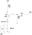
The human body induction circuit comprises a resistor R20, a MOS tube Q4, a human body induction sensor U5, a resistor R22 and a resistor R21; the output end of the voltage reduction circuit is connected with a resistor R20, a resistor R20 is connected with the source electrode of an MOS tube Q4, and the drain electrode of the MOS tube Q4 is connected with the first end of a human body induction sensor U5; the third end of the human body induction sensor U5 is grounded; the gate of the MOS transistor Q4 is connected to the resistor R21, one end of the resistor R22 is connected to the resistor R21, and the other end of the resistor R22 is grounded.
The gesture control circuit comprises a resistor R1, a resistor R2, a resistor R3, a capacitor C5, a resistor R4 and a gesture sensing sensor U4; one end of the resistor R1 is connected with the VCC end of the gesture induction sensor U4 and is connected with one end of the resistor R2, and the other end of the resistor R1 is connected with the SCl end of the gesture induction sensor U4; one end of the resistor R2 is connected with the output end of the voltage reduction circuit, and the other end of the resistor R2 is connected with the SDA end of the gesture induction sensor U4; the LDR end of the gesture induction sensor U4 is connected with the LEDK end of the gesture induction sensor U4; the GND terminal of the gesture sensing sensor U4 is grounded.
The output circuit comprises a switch S1, an ambient light sensor D4, a resistor R12, a chip U3, a capacitor C5, a resistor R11, a resistor R10, a MOS tube Q2 and a MOS tube Q1.
The second end of the human body induction sensor U5 is connected with the SDA end of the chip U3, one end of the resistor R2 is connected with the capacitor C5 through the resistor R3, and the capacitor C5 is connected with the GND end of the chip U3; the other end of the resistor R2 is connected with the SDA end of the chip U3 through a resistor R4; the resistor R21 is connected with the SCL end of the chip U3, and the other end of the resistor R1 is connected with the SCL end of the chip U3; the output end of the voltage reduction circuit is connected with the XCC end of the chip U3; the A1 end of the chip U3 is connected with a switch S1, and the switch S1 is grounded; one end of the resistor R10 is connected with the chip U3 and is grounded through a resistor R11, the other end of the resistor R10 is connected with the grid of the MOS transistor Q2, and the source of the MOS transistor Q2 is grounded; one end of the resistor R13 is connected with the PWM end of the chip U3 and is grounded through the resistor R12, the other end of the resistor R13 is connected with the grid electrode of the MOS transistor Q1, and the source electrode of the MOS transistor Q1 is grounded; the drain electrode of the MOS tube Q2, the drain electrode of the MOS tube Q1 and the input end of the voltage reduction circuit are connected with the first interface.
The illuminance detection circuit comprises an ambient light sensor D4 and a resistor R12; the output end of the voltage reduction circuit is connected with the anode of the ambient light sensor D4; the negative electrode of the ambient light sensor D4 is connected with the A2 end of the chip U3; the cathode of the ambient light sensor D4 is also connected to ground through a resistor R12.
The circuit is connected with the input interface through the voltage reduction circuit, supplies power to the voltage reduction circuit through an external connector, reduces voltage through the voltage reduction circuit and supplies power to the human body induction circuit, the gesture control circuit, the illumination detection circuit and the output circuit; the SCL end of the chip U3 outputs signals to control the human body induction circuit and the gesture control circuit to work.
An electric appliance C1, a polar capacitor C3 and a polar capacitor C4 in the voltage reduction circuit play a role in filtering; the voltage reduction effect is achieved through the inductor L1; the current limiting function is realized through the resistor R6 and the resistor R7; the diode D1 is used for realizing the function of freewheeling; resistor R8 and resistor R9 are used for feedback. When the human body induction circuit works, when the human body induction sensor U5 detects a human body, the second end of the human body induction sensor U5 outputs a signal to the SDA end of the chip U3; the output signal of the chip U3 is sent to the first interface to power the lamp body.
When the gesture reaction circuit works, when the gesture induction sensor U4 detects the action of a hand of a human body, the SDA end of the gesture induction sensor U4 outputs a signal to the SDA end of U3; the output signal of the chip U3 is sent to the first interface to power the lamp body.
Meanwhile, the PWM end of the chip U3 is connected with the MOS tube Q1; the A3 end of the chip U3 is connected with a MOS tube Q2; the MOS transistor Q1 and the MOS transistor Q2 are both connected with the first interface; therefore, the lamp body can be controlled to be turned on and off and the lighting color of the lamp body can be switched through the MOS tube Q1 and the MOS tube Q2.
The switch-on light S1 is connected with the A1 end of the chip U3, and the switch-on and switch-off of the lamp body and the switching of the lighting color of the lamp body are controlled by pressing the switch-on light S1.
An illuminance detection circuit is arranged, and power is supplied to the ambient light sensor D4 through the output of the voltage reduction circuit; the ambient light sensor D4 is used for illuminance detection; the ambient light sensor D4 outputs a signal to the chip U3 according to the current ambient illuminance, and the chip U3 controls the brightness of the lamp body according to the signal of the ambient light sensor D4.
The invention also provides an assembling method of the detachable lamp, which comprises the following steps: the first connecting part is inserted in the groove of one plug connector, the second inserting part is inserted in the groove of the other plug connector, the second interface is connected with the first interface, and the controller is electrically connected with the lamp body and the connected lamp bodies through the connectors.
According to the method, the first connecting part is inserted into the groove, and one end of the connecting part is stably connected with the plug connector; inserting the second connecting part into the other groove, and stably connecting one end of the connector with the other connector; meanwhile, the second interface is electrically connected with the first interface, and the adjacent plug connectors are connected through the connectors; the controller is electrically connected with the lamp bodies or the adjacent lamp bodies; when the controller is connected with the lamp body, any end of the controller and any end of the lamp body are connected through the connector, so that the lamp is convenient to use, and meanwhile, the irradiation range needs to be enlarged, and only any end of another lamp body needs to be connected with any end of the connected lamp body or any end of the controller; no orientation of the lamp body ends is required.
Drawings
Fig. 1 is a diagram showing a practical state of the detachable lamp.
Fig. 2 is another practical state diagram of the detachable lamp.
Fig. 3 is an exploded view of the detachable light.
Fig. 4 is a cross-sectional view a-a of fig. 3.
Fig. 5 is a sectional view of B-B in fig. 3.
Fig. 6 is a schematic view of a lamp body support in the removable lamp.
Fig. 7 is an exploded view of the lamp body of the removable light.
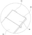
Fig. 8 is an enlarged view of a in fig. 7.
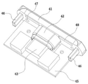
FIG. 9 is a perspective view of the connector of the detachable light being connected to a PCB.
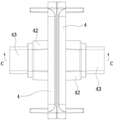
FIG. 10 is a schematic view of the rigid connector of the detachable light being connected to the two-part connector.
Fig. 11 is a cross-sectional view of C-C in fig. 10.
Fig. 12 is a schematic view of the rigid connector of fig. 11 separated from the two-part connector.
FIG. 13 is a schematic view of the lamp body in cooperation with one embodiment of the mounting bracket.
Fig. 14 is a schematic view of a lamp body mated with another embodiment of a mounting bracket.
Fig. 15 is a perspective view of a magnetic mount.
Figure 16 is a schematic view of a rigid connector.
Fig. 17 is a schematic view of a flexible connector.
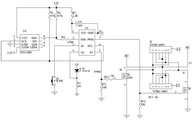
Fig. 18 is a schematic diagram of a step-down circuit.
FIG. 19 is a schematic diagram of a gesture control circuit and output circuit.
Fig. 20 is a schematic diagram of a human body sensing circuit.
FIG. 21 is a schematic diagram of the connection of the controller circuit to the first interface and the input interface in accordance with the present invention.
In the above figures: 1-a controller; 2-a lamp body; 3-a connector; 4-plug connector; 5-a concave groove; 11-an input interface; 12-a controller bracket; 13-controller cover plate; 21-a lamp body support; 22-LED light source; 23-a light guide plate; 24-a diffuser plate; 25-a lamp body cover plate; 26-magnetic attracting element; 27-a magnetic support; 28-arc support; 29-glue strip; 31-a second interface; 32-a first connection; 33-a second connecting portion; 34-a flexible connection; 41-seat body; 42-a plug-in part; 43-a first interface; 44-a groove; 45-PCB board; 46-an insertion portion; 47-first threaded hole; 48-fixing the groove; 121-a fourth mounting groove; 122-a second fixture; 123-a second support; 124-sixth mounting groove; 125-a fifth mounting groove; 211-a first mounting groove; 212-a first fixture; 213 a first support part; 214-a second mounting groove; 215-light exit; 216-a boss; 217-third mounting groove; 251-a first projection; 271-a first contact surface; 272-a limiting part; 273-fixing; 274-first via; 281-a clamping part; 2121-second threaded hole.
Detailed Description
The present invention will be described in further detail with reference to the accompanying drawings and specific embodiments.
As shown in fig. 1-21; a detachable light comprising a lighting device; the lighting device comprises a controller 1 and more than one lamp body 2; the adjacent lamp bodies 2 and the controller 1 and the lamp bodies 2 are detachably connected through connectors 3. The two ends of the controller 1 and the lamp body 2 are both provided with a plug connector 4; the plug connector 4 comprises a base body 41 and a plug-in part 42; one end of the seat body 41 is connected with one end of the insertion part 42; the other end of the inserting part 42 is connected with a first interface 43 and is coated on the outer surface of the first interface 43; the base body 41 is provided with a groove 44 depressed towards the insertion part 42; the groove 44 communicates with the first port 43; both ends of the connector 3 are provided with second interfaces 31 matched with the first interfaces 43; the connector 3 is inserted into the groove 44; the second port 31 is connected to the first port 43. The connector 3 is stably connected with the plug 4 by providing the groove 44.
The connector 3 further includes a first connection portion 32 and a second connection portion 33; the first connection portion 32 is connected to one second interface 31, and the second connection portion 33 is connected to the other second interface 31; the first connection portion 32 and the second connection portion 33 are adapted to be inserted into the groove 44. The first connecting part 32 and the second connecting part 33 are inserted into the groove 44; the connection strength of the connector 3 and the plug 4 is increased. In the present embodiment, the connector 3 is a rigid connector, and the first connection portion 32 and the second connection portion 33 are integrally provided and located between the two second ports 31.
When the rigid connector is used for connecting the two plug connectors 4; the adjacent plug connectors 4 are tightly attached; the rigid connector is hidden between adjacent plug connectors 4. The plug connector 4 at one end of the controller 1 can be tightly attached to the plug connector 4 at one end of the lamp body 2; the plug connector 4 at one end of the lamp body 2 can be tightly attached to the plug connector 4 at one end of the other lamp body 2; the rigid connector can be hidden between the controller 1 and the lamp body 2; the rigid connector may hide the lamp body 2 from the lamp body 2. In the embodiment, the plug connector 4 at one end of the controller 1 can be tightly attached to the plug connector 4 at one end of the lamp body 2, and the rigid connector is hidden between the controller 1 and the lamp body 2; a second port 31 at one end of the rigid connector passes through a groove 44 to be connected with the first port 43; the other second port 31 at one end of the rigid connector passes through the other groove 44 to be connected with the first port 43; the first connecting portion 32 is inserted into one groove 44, and the second connecting portion 33 is inserted into the other groove 44.
The adjacent plug connectors 4 are tightly attached; when the controller 1 is connected with the lamp body 2 and the lamp body 2 is connected with the lamp body 2; the controller 1 is tightly attached to the lamp body 2, and the lamp body 2 is tightly attached to the lamp body 2; shielding the rigid connector; the rigid connector is not exposed outside; the appearance is beautiful; when the controller 1 is connected with the lamp body 2 and the lamp body 2 is connected with the lamp body 2; inserted into the groove 44 through the rigid connection part; the rigid connecting part provides a supporting force for the adjacent plug-in connector 4; the rigid connecting part further plays a role in supporting the connection part of the controller 1 and the lamp body 2 and the connection part of the lamp body 2 and the lamp body 2; this enables stable use of the detachable lamp.
More than one first interface 43 is arranged on the controller 1 and the lamp body 2; connected with the first interface 43 through the connector 3; the controller 1 is detachably connected with more than one lamp body 2; since the controller 1 and the lamp body 2 both use the same first interface 43; when the lamp is installed and used, only one end of the controller 1 needs to be aligned with one end of the lamp body 2; then the controller 1 and the lamp body 2 are connected through the connector 3; the orientation of the end of the lamp body 2 does not need to be considered during installation; the use is convenient; meanwhile, the controller 1 can be connected with different ends of the lamp body 2; when a plurality of lamp bodies 2 need to be installed for use; only the other lamp body 2 is electrically connected with the lamp body 2 or the controller 1 through the connector 3; the number of the lamp bodies 2 and the position relation between the controller 1 and the lamp bodies 2 can be set according to the use scene; the use scene is extensive.
The controller 1 further comprises an input interface 11; the input interface 11 is disposed on the side of the controller 1 and between the two first interfaces 43 of the controller 1. The first interface 43, the second interface 31 and the input interface 11 are all Type-c interfaces; the first interface 43, the second interface 31 and the input interface 11 all use less than eight pins. In the present embodiment, the positive pins of the first interface 43, the second interface 31 and the input interface 11 are terminals a1, B1, a12 and B12; the negative pins of the first interface 43, the second interface 31 and the input interface 11 are terminals a4, B5, a9 and B9. The first interface 43, the second interface 31 and the input interface 11 all use less than eight pins; setting the positions of a positive electrode pin and a repolarization pin; the lamp body 2 is supplied with power through a connector matched with the input interface 11. When in use, the lamp body 2 is powered through the connector matched with the input interface 11; the input voltage is prevented from being higher than the working voltage of the lamp body 2, so that the lamp body 2 is prevented from being damaged; meanwhile, the connector needs to be matched with the input interface 11 for use; the power supply of other electrical products by using the connector can be avoided; the input voltage of the connector is higher than the working voltage of other electric appliance products, and other electric appliances are damaged.
In another implementation, the connector 3 is a flexible connector; the connector 3 further comprises a flexible connection 34; in this embodiment, the first connecting portion 32 and the second connecting portion 33 are provided separately, and the flexible connecting member 34 is connected between the first connecting portion 32 and the second connecting portion 33.
The flexible connecting piece 34 is arranged, so that one second interface 31 can move relative to the other second interface 31; when the lamp body 2 is used, the adjacent lamp body 2, the controller 1 and the lamp body 2 need to be separately installed due to the limitation of an installation scene, and when the plug connectors 4 of the adjacent lamp body 2, the plug connectors 4 of the controller 1 and the plug connectors 4 of the lamp body 2 are not on the same straight line; the adjacent lamp bodies 2, the controller 1 and the lamp bodies 2 are conveniently connected by using flexible connectors.
A concave groove 5 is formed at an opposite corner of the back surface of the lamp body and an opposite corner of the back surface of the controller. The lamp body 2 includes a lamp body support 21; the controller 1 includes a controller bracket 12. The cross section of the concave groove 5 is arc-shaped. The sunken groove extends along the length direction of lamp body and forms and link up the groove, and this structure, when installation lamps and lanterns, the area at the lamps and lanterns back reduces, lets the contact installation thing that lamps and lanterns can be better, simultaneously, sets up the sunken groove back in the upper and lower both sides at the back, and when installation lamps and lanterns, operating personnel's hand can grab lamps and lanterns and be difficult to the slippage, and the installation is all reliable with the dismantlement, lets the outward appearance of lamps and lanterns more pleasing to the eye simultaneously.
The lamp body 2 further includes an LED light source 22, a light guide plate 23, and a diffusion plate 24; the lamp body support 21 is provided with a first mounting groove 211, a first fixing member 212 and a first supporting portion 213; two first mounting grooves 211, two first fixing pieces 212 and two first supporting parts 213 are provided; the first mounting grooves 211 are disposed at both sides of the inside of the lamp body support 21; the two first fixing pieces 212 are arranged between the two first mounting grooves 211; the first supporting portion 213 is located between the first mounting groove 211 and the first fixing member 212 and above the first mounting groove 211 and the first fixing member 212. A second mounting groove 214 is formed between the two first supporting portions 213 and the two first fixing pieces 212. The first mounting groove 211 communicates with the second mounting groove 214.
The LED light source 22 is disposed in the first mounting groove 211; a light outlet 215 is formed in the side surface of the first mounting groove 211; the two light outlets 215 are disposed opposite to each other. The light guide plate 23 and the diffusion plate 24 are disposed in the second mounting groove 214 and between the two light outlets 214. The diffusion plate 24 is disposed above the light guide plate 23; the light emitting direction of the LED light source 22 is perpendicular to the light emitting direction of the light guide plate 23 and the light emitting direction of the diffusion plate 24; the top of the lamp body support 21 is provided with a convex part 216; the raised portions 216 are at a higher level than the diffuser plate 24, which protects the diffuser plate. The LED light source 22 is disposed inside the lamp body support 21, and the light emitting direction is perpendicular to the light emitting direction of the light guide plate 23 and the light emitting direction of the diffusion plate 24; the LED light source 22 is emitted from the side surface of the light guide plate 23, and is refracted and then emitted from the front surface of the light guide plate 23; glare caused by the direct view of the LED light source 22 by a user is avoided; the light guide plate 23 is arranged to enable the lamp body 2 to emit light uniformly; the irradiation range of the lamp body 2 is increased by providing the diffusion plate 24.
The lamp body 2 further includes a lamp body cover plate 25; two lamp body cover plates 25 are arranged; the diffusion plate 24 is located between the two lamp cover plates 25; the lamp body cover 25 is mounted in the second mounting groove 214. The first interface 43 is connected with a PCB 45; the lamp body support 21 is further provided with a third mounting groove 217; the third mounting groove 217 is positioned below the two first fixing pieces 212; the PCB 45 is arranged in the third mounting groove 217 and is in clearance fit with the third mounting groove 217; through PCB board 45 and third mounting groove 217 clearance fit, avoid PCB board 45 and the inseparable laminating of third mounting groove 217, the great PCB board 45 damage that leads to of stress that PCB board 45 received.
The plug-in unit 4 further comprises an insertion portion 46; the insertion portion 46 is formed by extending from the base 41 toward the insertion portion 42; the insertion portions 46 are provided at both ends of the seat body 41; the insertion portion 46 is used to be connected with the first mounting groove 211; the seat body 41 comprises more than one first threaded hole 47; the first mount 212 includes a second threaded hole 2121. The first threaded hole 47 is adapted to interface with the second threaded hole 2121 and be screwed thereto. When the lamp body 2 is assembled, the LED light source 22 is installed in the first installation groove 211; the light guide plate 23 and the diffusion plate 24 are mounted in the second mounting groove 214; then, the lamp body cover plates 25 are respectively installed at both ends of the second installation groove 214; then, the plug connectors 4 are respectively arranged at the two ends of the lamp body bracket 21; the insertion portion 46 is installed in the first installation groove 211; the PCB board 45 is mounted in the third mounting groove 217; the first and second threaded holes 47 and 2121 are then screwed together.
In this embodiment, a first protrusion 251 is protruded from one end of the lamp body cover plate 25 away from the diffusion plate 24; one side of the seat body 41 close to the lamp body 2 is inwards recessed with a fixing groove 48; when the plug-in unit 4 is mounted on the lamp body 2, the first projection 251 is inserted into the fixing groove 48, improving the stability of the connection of the plug-in unit 4 with the lamp body 2.
The controller bracket 12 is provided with a fourth mounting groove 121, a second fixing member 122, a second supporting portion 123 and a sixth mounting groove 124; two fourth mounting grooves 121, two second fixing pieces 122 and two second supporting parts 123 are provided; the fourth mounting groove 121 is disposed at both sides of the inside of the controller bracket 12; the two second fixing pieces 122 are disposed between the two fourth mounting grooves 121. A fifth mounting groove 125 is formed above the two second fixing pieces 122; the fifth mounting groove 125 is located between the second supporting portions 123. The sixth mounting groove 124 is located below the two second fixing pieces 122.
The controller 1 includes a controller cover 13; the controller cover 13 is mounted in the fifth mounting groove 125. The PCB board 45 is disposed in the sixth mounting groove 124 and is clearance-fitted with the sixth mounting groove 124. The second fixing member 122 is provided with a third screw hole (not shown). The first threaded hole 47 is for connection with the third threaded hole. When the controller 1 is assembled, the controller cover plate 13 is installed in the fifth installation groove 125, and then the plug connectors 4 are respectively installed at the two ends of the controller bracket 12; the insertion portion 46 is mounted in the fourth mounting groove 121; the PCB board 45 is mounted in the sixth mounting groove 124; the first threaded hole 47 is then screwed to the third threaded hole.
In the present embodiment, one end of the controller cover plate 13 close to the plug 4 is provided with a second protrusion (not shown in the figure); the second projection is the same structure as the first projection 251; when the plug-in unit 4 is mounted on the controller 1, the second protrusion is inserted into the fixing groove 48, improving the stability of the connection of the plug-in unit 4 with the controller 1.
The lamp body 2 further comprises a magnetic attraction piece 26; more than one magnetic suction piece 26 is arranged; the magnetic attraction piece 26 is fixed in the lamp body bracket 21; the lamp body 2 further comprises a mounting bracket; the two mounting brackets are arranged on the lamp body bracket 21, one mounting bracket is arranged at one end of the lamp body bracket 21, and the other mounting bracket is arranged at the other end of the lamp body bracket 21. The mounting bracket is used for mounting the lamp body bracket 21; this achieves the mounting of the lamp body 2.
In the present embodiment, the mounting bracket is a magnetic bracket 27; the magnetic bracket 27 is matched with the magnetic attraction piece 26; the magnetic attraction member 26 attracts the lamp body support 21 to the magnetic support 27.
The magnetic holder 27 includes a first contact surface 271 and a stopper 272; the stopper portions 272 are provided on both sides of the magnetic bracket 27; the limiting part 272 is used for acting with the grabbing structure 5 of the lamp body bracket 21; when the magnetic element 26 is attracted to the magnetic support 27; the two grabbing structures 5 are located between the two limiting parts 272; the limiting part 272 has the same shape as the grabbing structure 5; by the action of the limiting part 272 on the grabbing structure 5, the lamp body support 21 is prevented from shaking on the magnetic support 27.
The first contact surface 271 is used for contacting the bottom of the lamp body support 21; the first contact surface 271 is recessed away from the lamp body holder 21 to form a fixing portion 273; a first through hole 274 is provided in the fixing portion 273; the bottom of the magnetic bracket 27 is also provided with an adhesive tape 29; the adhesive tape 29 is provided with a second through hole (not shown in the figure); a first through hole 274 and a second through hole for passing a screw; the fixing portion 273 is recess-formed; thus, a receiving space is formed between the fixing portion 273 and the lamp body support 21; further, when the magnetic bracket 27 is fixed by using the screw, the top of the screw is flush with the first contact surface 271; the screw does not prevent the first contact surface 271 from adhering to the lamp body holder 21. When the magnetic bracket 27 is installed, the magnetic bracket can be fixed through the adhesive tape 29; the magnetic bracket 27 can also be fixed by screws; the magnetic support 27 can also be fixed simultaneously by means of the adhesive strip 29 and screws.
In another embodiment, the mounting bracket is an arc-shaped bracket 28 with elasticity; the arc-shaped bracket 28 is clamped on the side surface of the lamp body bracket 21; the arc-shaped support 28 comprises a second contact surface (not shown in the figure) and a clamping part 281; the clamping parts 281 are arranged at both sides of the magnetic bracket 27; the clamping part 281 is clamped on the side surface of the lamp body support 21. The side of lamp body support 21 is acted by clamping part 281 to avoid the shaking of lamp body support 21 on arc support 28.
The second contact surface is used for contacting the bottom of the lamp body support 21; the second contact surface is recessed away from the lamp body support 21 to form a fixing part 273; a first through hole 274 is provided in the fixing portion 273; the bottom of the arc-shaped bracket 28 is also provided with an adhesive tape 29; the adhesive tape 29 is provided with a second through hole (not shown in the figure); a first through hole 274 and a second through hole for passing a screw; the fixing portion 273 is recess-formed; thus, a receiving space is formed between the fixing portion 273 and the lamp body support 21; when the magnetic bracket 27 is fixed by using the screw, the top of the screw is flush with the second contact surface; the screws do not prevent the second contact surface from adhering to the lamp body holder 21. When the device is installed, the arc-shaped bracket 28 can be fixed through the adhesive tape 29; the arc-shaped bracket 28 can also be fixed through screws; the arc-shaped bracket 28 can also be fixed by the adhesive tape 29 and the screw at the same time.
The controller comprises a voltage reduction circuit, a human body induction circuit, a gesture control circuit, an illumination detection circuit and an output circuit; the voltage reduction circuit comprises a polar capacitor C1, a resistor R5, a capacitor C2, a chip U1, a diode D1, an inductor L1, a resistor R6, a resistor R7, a polar capacitor C3, a polar capacitor C4, a resistor R8 and a resistor R9. Chip U1 is model TX 4151.
VIN of the chip U1 is connected with the input end of a voltage reduction circuit, the input end of the voltage reduction circuit is connected with an input interface J1, COMP end of the chip U1 is connected with a capacitor C2 through a resistor R5, a capacitor C2 is grounded and connected with the input interface, and a polarity capacitor C1 is connected between VIN of the chip U1 and the ground; the SW end of the chip U1 is connected with an inductor L1, and the inductor L1, a resistor R7 and the output end of the voltage reduction circuit are sequentially connected; a resistor R8 is connected between the resistor R7 and the voltage reduction circuit, and the other end of the resistor R8 is connected with the FB end of the chip U1; one end of the resistor R7 is connected with one end of the polar capacitor C3, the other end of the polar capacitor C3 is grounded, the other end of the resistor R7 is connected with one end of the polar capacitor C4, the other end of the resistor R7 is connected with the CS-end of the chip U1, and the other end of the polar capacitor C4 is grounded; the resistor R6 is connected with the resistor R7 in parallel; the cathode of the diode D1 is connected with the input end of the inductor L1, and the output end of the inductor L1 is also connected with the CS + end of the chip U1; the anode of the diode D1 is grounded; the resistor R8 is connected with the resistor R9 in series, and the resistor R9 is grounded; the GND terminal of the chip U1 is connected to ground.
The human body induction circuit comprises a resistor R20, a MOS tube Q4, a human body induction sensor U5, a resistor R22 and a resistor R21; the output end of the voltage reduction circuit is connected with a resistor R20, a resistor R20 is connected with the source electrode of an MOS tube Q4, and the drain electrode of the MOS tube Q4 is connected with the first end of a human body induction sensor U5; the third end of the human body induction sensor U5 is grounded; the gate of the MOS transistor Q4 is connected to the resistor R21, one end of the resistor R22 is connected to the resistor R21, and the other end of the resistor R22 is grounded.
The gesture control circuit comprises a resistor R1, a resistor R2, a resistor R3, a capacitor C5, a resistor R4 and a gesture sensing sensor U4; gesture-sensitive sensor U4 is model UCS 14266.
One end of the resistor R1 is connected with the VCC end of the gesture sensing sensor U4 and connected with one end of the resistor R2, and the other end of the resistor R1 is connected with the SCL end of the gesture sensing sensor U4; one end of the resistor R2 is connected with the output end of the voltage reduction circuit, and the other end of the resistor R2 is connected with the SDA end of the gesture induction sensor U4; the LDR end of the gesture induction sensor U4 is connected with the LEDK end of the gesture induction sensor U4; the GND terminal of the gesture sensing sensor U4 is grounded.
The illuminance detection circuit comprises an ambient light sensor D4 and a resistor R12; the output end of the voltage reduction circuit is connected with the anode of the ambient light sensor D4; the negative electrode of the ambient light sensor D4 is connected with the A2 end of the chip U3; the cathode of the ambient light sensor D4 is also connected to ground through a resistor R12. Ambient light sensor D4 model UCS3106
The output circuit comprises a chip U3, a capacitor C5, a resistor R11, a resistor R10, a MOS tube Q2 and a MOS tube Q1; in this embodiment, the chip U3 is a single chip.
The second end of the human body induction sensor U5 is connected with the SDA end of the chip U3, one end of the resistor R2 is connected with the capacitor C5 through the resistor R3, and the capacitor C5 is connected with the GND end of the chip U3; the other end of the resistor R2 is connected with the chip U3 through a resistor R4; the resistor R21 is connected with the SCL end of the chip U3, and the other end of the resistor R1 is connected with the SCL end of the chip U3; the output end of the voltage reduction circuit is connected with a VCC end of the chip U3; one end of the resistor R10 is connected with the chip U3 and is grounded through a resistor R11, the other end of the resistor R10 is connected with the grid of the MOS transistor Q2, and the source of the MOS transistor Q2 is grounded; one end of the resistor R13 is connected with the PWM end of the chip U3 and is grounded through the resistor R12, the other end of the resistor R13 is connected with the grid electrode of the MOS transistor Q1, and the source electrode of the MOS transistor Q1 is grounded; the drain electrode of the MOS tube Q2, the drain electrode of the MOS tube Q1 and the input end of the voltage reduction circuit are connected with the first interface.
The A1 terminal of the chip U3 is connected with the switch S1, and the switch S1 is grounded.
The human body induction circuit, the gesture control circuit, the illumination detection circuit and the output circuit are powered; SCL end output signal control human body induction circuit and the work of gesture control circuit of chip U3, specifically be, when chip U3 gives resistance R21 a signal, MOS pipe Q4 switches on, and then human body induction sensor U5 gets electricity to carry out normal work. When the chip U3 sends a signal to the gesture sensor U4, the gesture sensor U4 is activated.
The capacitor C1, the polar capacitor C3 and the polar capacitor C4 in the voltage reduction circuit play a role in filtering; the voltage reduction effect is achieved through the inductor L1; the current limiting function is realized through the resistor R6 and the resistor R7; the diode D1 is used for realizing the function of freewheeling; the resistor R8 and the resistor R9 are used for feeding back the output voltage signal. When the human body induction circuit works, when the human body induction sensor U5 detects a human body, the second end of the human body induction sensor U5 outputs a signal to the SDA end of the chip U3; the output signal of the chip U3 is sent to the first interface to power the lamp body.
When the gesture reaction circuit works, when the gesture induction sensor U4 detects the action of a hand of a human body, the SDA end of the gesture induction sensor U4 outputs a signal to the SDA end of U3; the output signal of the chip U3 is sent to the first interface to power the lamp body.
Meanwhile, the PWM end of the chip U3 is connected with the MOS tube Q1; the A3 end of the chip U3 is connected with a MOS tube Q2; the MOS transistor Q1 and the MOS transistor Q2 are both connected with the first interface; therefore, the lamp body can be controlled to be turned on and off and the lighting color of the lamp body can be switched through the MOS tube Q1 and the MOS tube Q2.
The switch-on light S1 is connected with the A1 end of the chip U3, and the switch-on and switch-off of the lamp body and the switching of the lighting color of the lamp body are controlled by pressing the switch-on light S1, so that the switch-on and switch-off of the lamp are manually controlled.
An illuminance detection circuit is arranged, and power is supplied to the ambient light sensor D4 through the output of the voltage reduction circuit; the ambient light sensor D4 is used for illuminance detection; the ambient light sensor D4 outputs a signal to the chip U3 according to the current ambient illuminance, and the chip U3 controls the brightness of the lamp body according to the signal of the ambient light sensor D4.
A method of assembling a removable light comprising the steps of:
and (1) connecting a lamp body at one end of the controller.
And (2) connecting another lamp body to the other end of the controller or the connected lamp body.
And (3) repeating the steps (1) to (2), and increasing the number of the lamp bodies until the lighting requirement is met.
In the step (1) and the step (2), connecting adjacent plug connectors through connectors; the first connecting part is inserted in the groove of one plug connector, the second inserting part is inserted in the groove of the other plug connector, the second interface is connected with the first interface, and the controller is electrically connected with the lamp body and the connected lamp bodies through the connectors.
Comprising steps (a) to (b) before step (1);
assembling a lamp body, and installing an LED light source in a first installation groove; then, installing the light guide plate and the diffusion plate in the second installation groove; then, lamp body cover plates are respectively arranged at two ends of the second mounting groove; then installing plug connectors at two ends of the lamp body bracket respectively; the insertion part is installed in the first installation groove; the PCB is arranged in the third mounting groove; the first protrusion is inserted into the fixing groove; and then the first threaded hole is connected with the second threaded hole through a screw.
Assembling a controller, namely installing a controller cover plate in a fifth installation groove, and then respectively installing plug connectors at two ends of a controller bracket; the insertion part is installed in the fourth installation groove; the PCB is arranged in the sixth mounting groove; the second projection is inserted into the fixing groove; and then the first threaded hole is connected with the third threaded hole through a screw.
According to the method, the first connecting part is inserted into the groove, and one end of the connecting part is stably connected with the plug connector; inserting the second connecting part into the other groove, and stably connecting one end of the connector with the other connector; meanwhile, the second interface is electrically connected with the first interface, and the adjacent plug connectors are connected through the connectors; the controller is electrically connected with the lamp bodies or the adjacent lamp bodies; when the controller is connected with the lamp body, any end of the controller and any end of the lamp body are connected through the connector, so that the lamp is convenient to use, and meanwhile, the irradiation range needs to be enlarged, and only any end of another lamp body needs to be connected with any end of the connected lamp body or any end of the controller; no orientation of the lamp body ends is required.