Disclosure of Invention
The invention aims to provide a straw smashing, centralized and deep-buried rotary tillage and ridging comprehensive operation machine which can smash crop straws and return the crushed crop straws to a furrow, so that normal seeding of planting ridges and growth of crops are not influenced, air pollution is prevented, and the straws are converted into fertilizer which can be absorbed and utilized by the crops.
The technical scheme of the invention is as follows:
a straw smashing, centralized deep-burying, rotary tillage and ridging integrated operation machine comprises a frame, a transmission mechanism, finger disc assemblies, a straw picking and smashing mechanism, a straw returning mechanism, a rotary tillage mechanism and a ridging mechanism, wherein the left side and the right side of the front end of the frame are respectively provided with one finger disc assembly, the straw picking and smashing mechanism is arranged below the front portion of the frame, the left side and the right side of the upper surface of the frame are respectively provided with one straw returning mechanism, the rotary tillage mechanism is arranged at the rear portion of the frame, the ridging mechanism is arranged at the rear end of the frame, and the transmission mechanism drives the straw picking and smashing mechanism, the straw returning mechanism and the rotary tillage mechanism to operate; the ridging mechanism comprises a plurality of ridging plough components, and a ridging plough component is arranged in front of a straw outlet of each straw returning mechanism.
The transmission mechanism comprises a power input shaft, a first transmission shaft, a first gearbox, a second transmission shaft, a second gearbox, a first side box and a second side box; one end of the power input shaft is connected with a power output shaft of the tractor through a universal joint, the other end of the power input shaft is connected with a first transmission shaft through the universal joint, the other end of the first transmission shaft is connected with an input shaft of a first gearbox through the universal joint, output shafts on the left side and the right side of the first gearbox are connected with a first output shaft and a second output shaft through the universal joint, an output shaft at the rear end of the first gearbox is connected with a second transmission shaft through the universal joint, the other end of the second transmission shaft is connected with an input shaft of the second gearbox through the universal joint, output shafts on the left side and the right side of the second gearbox are connected with a third output shaft and a fourth output shaft through the universal joint, the first output shaft penetrates through the rack and is rotatably connected with the rack, and a first belt pulley and a second belt pulley are sleeved at the other end of the first output shaft; the second output shaft penetrates through the rack and is rotationally connected with the rack, and a third belt pulley and a fourth belt pulley are sleeved at the other end of the second output shaft; the other end of the third output shaft is connected with an input shaft of the first side box through a universal joint; the other end of the fourth output shaft is connected with an input shaft of the second side box through a universal joint.
The finger disc assembly comprises a finger disc, two positive and negative buckle adjusting bolts, a finger disc inclined rod and a finger disc height rod, wherein one end of the finger disc inclined rod is fixedly connected with the finger disc shaft, the other end of the finger disc inclined rod is hinged with a first positive and negative buckle adjusting bolt, and the other end of the first positive and negative buckle adjusting bolt is hinged with the rack; the utility model discloses a high pole of finger dish, including connecting rod, connecting rod other end, the connecting rod other end is connected with the frame, and the connecting rod other end is opening "U" type structure, and in the opening of connecting rod was arranged in to the finger dish axle, the bolt passed the connecting rod and the epaxial through-hole of finger dish connected the two, and second positive and negative knot adjusting bolt one end is articulated with connecting rod and connecting rod junction, and the other end is articulated with the frame.
The straw picking and smashing mechanism comprises a picking mechanism, a smashing mechanism and a straw collecting cover, the straw collecting cover is fixed on the machine frame, the picking mechanism and the smashing mechanism are arranged in the straw collecting cover, the smashing mechanism is arranged on the rear upper surface of the picking mechanism, the picking mechanism comprises a picking cutter shaft, two ends of the picking cutter shaft penetrate through the machine frame and are rotatably connected with the left side and the right side of the machine frame, and a picking claw is spirally arranged on the periphery of the picking cutter shaft; a first belt pulley sleeved on the first output shaft is in transmission connection with a crushing mechanism belt pulley sleeved at the end part of the crushing cutter shaft through a belt; the crushing mechanism comprises a crushing cutter shaft, two ends of the crushing cutter shaft penetrate through the rack and are rotatably connected with the left side and the right side of the rack, and crushing claws are spirally arranged on the periphery of the crushing cutter shaft; a third belt pulley sleeved on the second output shaft is in transmission connection with a picking mechanism belt pulley sleeved at the end part of the picking cutter shaft through a belt; the straw collecting cover is characterized in that a transverse straw feeding port penetrating through the whole rack is formed in the lower portion of the straw collecting cover, straw discharging ports are formed in the left side and the right side of the upper portion of the straw collecting cover, a row of fixed knives facing the picking mechanism are fixed on the front edge of the straw feeding port below the straw collecting cover, two rows of fixed knives are fixed on the rear edge of the straw feeding port, the front row of fixed knives face the front side, the rear row of fixed knives face the rear side, and the fixed knives face a picking claw or a space between a crushing claw and a crushing claw.
The straw returning mechanism comprises a self-suction fan, a conveying pipeline, a straw gathering cover, an auger outer cover, an auger driving mechanism and a straw press roller device; the self-suction fan is fixed on the front part of the rack, an inlet of the self-suction fan is connected with a straw discharge port of the straw picking and crushing mechanism through a pipeline, a fan belt pulley is sleeved on an input shaft of the self-suction fan, and a second belt pulley or a fourth belt pulley drives the fan belt pulley to rotate through a belt; from inhaling formula fan export fixed connection pipeline one end, pipeline extends backward, and the other end is arranged in the straw and is gathered together the cover, the straw is gathered together the cover in front and is the screw feeder dustcoat, and the straw gathers together the cover and is linked together with the screw feeder dustcoat, is equipped with fore-and-aft screw feeder in the screw feeder dustcoat, and the screw feeder transmission shaft passes through the bearing to be fixed in the screw feeder dustcoat, screw feeder actuating mechanism includes hydraulic motor, drive shaft, first bevel gear, second bevel gear, the drive shaft both ends are transversely installed on the frame through the bearing frame, hydraulic motor fixes in the frame, hydraulic motor's output shaft is connected with drive shaft one end, respectively installs first bevel gear at the both ends of drive shaft, first bevel gear meshes with the second bevel gear of screw feeder transmission shaft upper end, straw compression roller device includes straw compression roller frame, straw compression roller, spring, the screw feeder dustcoat is connected the straw compression roller frame through the tie-beam in the lower part, the straw press roll frame comprises a screw rod and an inverted U-shaped frame fixedly connected with the lower end of the bolt, the screw rod is sleeved with a spring, the upper end of the screw rod penetrates through the connecting beam and is locked by a nut, and the inverted U-shaped frame is rotatably connected with the left side and the right side of the straw press roll shaft.
The rotary tillage mechanism comprises two rotary tillers, one end of a cutter shaft of the first rotary tiller is connected with an output shaft of the first side box, the other end of the cutter shaft of the first rotary tiller is connected with the rack in a rotating mode, one end of a cutter shaft of the second rotary tiller is connected with the output shaft of the second side box, and the other end of the cutter shaft of the second rotary tiller is connected with the rack in a rotating mode.
The ridging plough subassembly comprises ridging plough and ridging plow frame, the ridging plow frame is installed on the crossbeam of frame rear end, the ridging plow frame comprises riser and U type frame, and it has the hole to open on the U type frame, it has a plurality of holes to open on the shank of ridging plough, and in the U type frame was arranged in to the shank, the bolt passed the hole on the U type frame and the hole on the shank couples together the two.
The spraying device comprises a frame, a stirring auger and a spraying mechanism, wherein the frame is provided with a spraying opening, the spraying opening is connected with the stirring auger through a pipeline, the spraying mechanism comprises a pesticide box, a high-pressure spraying pump, a pipeline and a spraying head, the pesticide box is fixed at the upper part of the frame, the outlet of the pesticide box is connected with the inlet of the high-pressure spraying pump through the pipeline, the outlet of the high-pressure spraying pump is connected with the spraying head through the pipeline, and the spraying head is inserted into the outer cover of the stirring auger; and a fifth belt pulley is mounted on an output shaft at the rear end of the second gearbox, a sixth belt pulley is mounted on an input shaft of the high-pressure spray pump, and the fifth belt pulley and the sixth belt pulley are in belt transmission.
The frame rear end passes through the compression roller tie-beam and rotates the connection compression roller, the compression roller tie-beam is formed by preceding "V" type roof beam and the articulated connection of the straight beam in back.
The two side surfaces of the rack are provided with a first pinch roller mechanism, a second pinch roller mechanism and two connecting plates, the first pinch roller mechanism comprises two first bending plates, a first pinch roller and a first spring, the lower ends of the two first bending plates are connected through a first connecting rod, holes are formed in the bending positions of the two first bending plates, a first bolt penetrates through the two holes to be rotatably connected with the first bending plates, one end of the first spring is sleeved on the first connecting rod, the other end of the first spring is sleeved on the rack, the two ends of a shaft of the first pinch roller are rotatably connected with the other ends of the two first bending plates, and the first pinch roller is arranged on a belt between a first belt pulley and a crushing mechanism belt pulley or a belt between a third belt pulley and a picking mechanism belt pulley; the second pinch roller mechanism comprises two second bending plates, a second pinch roller and a second spring, the lower ends of the two second bending plates are connected through a second connecting rod, the bending positions of the two second bending plates are provided with holes, a second bolt penetrates through the two holes to be rotatably connected with the second bending plates, the two ends of a shaft of the second pinch roller are rotatably connected with the upper ends of the two second bending plates, one end of the second spring is sleeved on the first screw rod, the other end of the second spring is sleeved on the second connecting rod, and the second pinch roller is arranged on a second belt pulley or a belt between a fourth belt pulley and a fan belt pulley; the two connecting plates are respectively arranged on the outer sides of the two first bending plates, the lower ends of the two connecting plates are sleeved on the first bolts, the two connecting plates are arranged on the outer sides of the two second bending plates, and the upper ends of the two connecting plates are sleeved on the second bolts.
The invention has the beneficial effects that:
1. this application is synthesized workover rig and is directly carried the frame back with the straw through straw returning to the field mechanism, and after the ridging mechanism ridging, the straw is direct to be led into in the furrow, solves among the prior art and spills the straw to on the ridge of beating or the straw smashes the problem that the rotary tillage brought simultaneously.
2. The utility model provides an in the furrow on good ridge is directly carried to the workover rig with kibbling straw to through the process of burying deeply with the suppression, the straw is concentrated and is buried deeply, prevents that the straw from being blown away by wind, does benefit to moreover and changes into organic matter.
3. The finger dish of the preceding both sides of this application frame can be gathered together the straw of about 10 centimetres in the frame outside in front, prevents that the straw of frame both sides from not having been picked up by the pickup, stays ground, will not bury in the planting ridge of both sides by the straw that has not been picked up when the normal rotary tillage of rotary tillage, ridging mechanism behind the frame, ridging in addition.
4. This application indicates the dish assembly, can adjust the height that indicates the dish apart from ground through adjusting the length of the positive and negative knot regulating stem of second, can adjust the inclination of pointing the dish for the direction of advance through adjusting the length of the first positive and negative knot regulating stem, and is more nimble.
5. This application is equipped with charge device, and the medicine in the medical kit is through pipeline and high-pressure spray pump, mixes the medicine through the nozzle in the straw that is carried down by the screw feeder, and the export discharge from the screw feeder lower extreme prevents that the straw from producing the pest, promotes the straw fermentation together.
6. This application is synthesized operation machine and is installed the claw of picking up including picking up mechanism and rubbing crusher structure at the arbor of picking up mechanism spiral form, can pick up the straw and carry out preliminary smashing, is thrown rubbing crusher structure department at the back through preliminary kibbling straw, and rubbing crusher structure is with picking up mechanism, and the straw that will tentatively smash is smashed once more, is siphoned away by the fan at last. The prior art is all picking up and smashing, does not have the regrinding, leads to one side through the spiral shaft and is siphoned away by the fan. The straw of this application is through smashing twice, and is smashed effectually. And the picking and crushing operation is separated, so that the straw is picked up cleanly and the crushing effect is good.
7. This application is collected at the straw and is installed the stationary knife below the cover, and the position of stationary knife installation faces crushing claw or picks up the space between the claw, can carry on spacingly to the straw, and control does benefit to and picks up the claw and pick up the operation in certain region, does benefit to crushing claw crushing operation, makes the straw smash effectually.
8. The part of this application frame side's drive mechanism drives through the belt and inhales formula fan and pick-up mechanism and rubbing crusher structure certainly. In addition, first pinch roller mechanism and second pinch roller mechanism prevent that the belt from too pine, influencing the transmission.
9. This application hydraulic motor drives the drive shaft and then through the mutual interlock of first bevel gear and second bevel gear, drives decurrent screw feeder transmission shaft, and the screw feeder blade is rotatory pushes down the straw, is equipped with the ridging plough in front of screw feeder dustcoat lower extreme, and in the ridging plough ditching, the straw was arranged the furrow from the straw discharge port below the screw feeder dustcoat, was buried deeply to the suppression buries two furrows deeply whole straw. This application still is equipped with spouts medicine mechanism, and straw and medicine mix in the screw feeder dustcoat, and then arrange the furrow in for straw conversion organic matter prevents the straw worm that lives when.
Detailed Description
Aiming at the problems that the straws are directly crushed and thrown on the land at the present stage to influence the emergence and growth of corns and the fertilizer is not easy to be absorbed, the applicant invents the straw crushing, concentrated deep-burying, rotary-tillage and ridging comprehensive operation machine. The present application will now be described in detail with reference to the accompanying drawings:
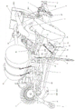
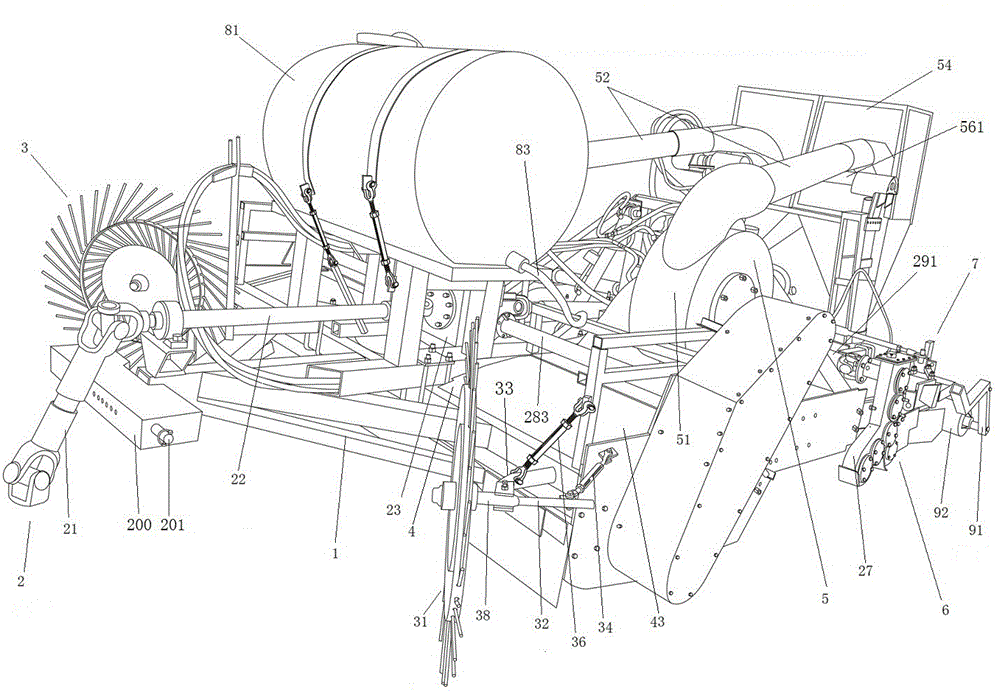
as shown in figures 1 and 2 of the drawings,
a straw smashing, centralized and deep-buried rotary tillage and ridging comprehensive operation machine comprises a frame 1, a transmission mechanism 2, a finger disc assembly 3, a straw picking and smashing mechanism 4, a straw returning mechanism 5, a rotary tillage mechanism 6 and a ridging mechanism 7. The left side and the right side of the front end of the frame 1 are respectively provided with a finger plate assembly 3, and a straw picking and smashing mechanism 4 is arranged below the front part of the frame 1. The left side and the right side of the upper surface of the frame 1 are respectively provided with a straw returning mechanism 5. The rear part of the frame 1 is provided with a rotary tillage mechanism 6, and the rear end of the frame 4 is provided with a ridging mechanism 7. The transmission mechanism 2 drives the straw picking and crushing mechanism 4, the straw returning mechanism 5 and the rotary tillage mechanism to operate 6. Ridging mechanism 7 includes a plurality of ridging plough subassemblies 71, shows in the application drawing to be five ridging plough subassemblies 71, can play four planting ridges simultaneously. The front of the straw outlet of each straw returning mechanism is provided with a ridging plough component, and the ridging plough component in front of the straw outlet can be arranged at the rear end of the frame and also can be arranged in front of the straw outlet of the straw returning mechanism. The machine is connected with the rear end of a tractor through a connecting plate, and particularly in the attached drawings of the application, the connecting plate 200 is connected with a balance arm of the tractor through a pin shaft 201. The machine is additionally provided with wheels 300 and landing gear 400, which may be of conventional design in the art. The landing gear 400 that shows in the present application drawing includes undercarriage 4001 and pneumatic cylinder 4002, the undercarriage is fixed in the frame, and pneumatic cylinder one end is connected with the undercarriage, and the other end is connected with the axletree. When the comprehensive working machine does not work, the hydraulic cylinder is used for supporting the comprehensive working machine by taking the pin shaft 201 as a shaft, and the whole comprehensive working machine falls down during working.
This application is synthesized operation machine and is gathered together the straw through preceding two finger dish assemblies about with the straw and collect the frame preceding, picks up rubbing crusher structure through the straw and picks up the straw and pick up simultaneously and smash, gets into straw still field mechanism through the straw discharge gate after smashing, and the straw is then led the frame at the back. After the land is rotary-tilled, the land is ridged by a ridging mechanism, and the crushed straws are thrown into furrows. The ridging plough assembly and the straw discharge port are arranged in front of and behind each other, the ridging plough ploughs furrows firstly, and the crushed straws are guided to the rear of the machine frame by the straw returning mechanism and are discharged into the furrows from the straw discharge port. The straws in the furrows are covered by the soil falling back during ditching, and the problem caused by random throwing of the straws in the prior art is solved.
As shown in fig. 1, 2 and 5, the transmission mechanism 2 includes a power input shaft 21, a first transmission shaft 22, a first gearbox 23, a second transmission shaft 24, a second gearbox 25, a first side box 26 and a second side box 27.
One end of the power input shaft 21 is connected with a power output shaft of the tractor through a universal joint, the other end of the power input shaft is connected with a first transmission shaft 22 through a universal joint, the other end of the first transmission shaft 22 is connected with an input shaft of a first gearbox 23 through a universal joint, output shafts on the left side and the right side of the first gearbox 23 are connected with a first output shaft 28 and a second output shaft 283 through universal joints, an output shaft on the rear end of the first gearbox 23 is connected with a second transmission shaft 24 through a universal joint, the other end of the second transmission shaft 24 is connected with an input shaft of a second gearbox 25 through a universal joint, and output shafts on the left side and the right side of the second gearbox 25 are connected with a third output shaft 29 and a fourth output shaft 291. The power is transmitted to the first gearbox through the power input shaft and the first transmission shaft, and the first gearbox transmits the power to the two sides of the rack through the first output shaft and the second output shaft respectively, so that the picking mechanism, the crushing mechanism and the self-suction fan are driven to operate. And the second gearbox transmits power to the two sides of the rack through a third output shaft and a fourth output shaft respectively, so that the first side box and the second side box are driven to operate. An output shaft behind the second gearbox drives the high-pressure spray pump to operate through a belt.
The first output shaft 28 penetrates through the rack and is rotationally connected with the rack, and the other end of the first output shaft is sleeved with a first belt pulley 281 and a second belt pulley 282; the first belt pulley 281 drives a cutter shaft of the crushing mechanism to rotate through a belt, so that straw crushing work is performed. The second belt pulley drives a self-suction fan of the straw returning mechanism to work through a belt.
The second output shaft penetrates through the rack and is rotationally connected with the rack, and a third belt pulley and a fourth belt pulley are sleeved at the other end of the second output shaft; the third belt pulley drives a cutter shaft of the picking mechanism to rotate through a belt, so that straw picking work is carried out. The fourth belt pulley drives the self-suction fan of the straw returning mechanism at the other side to work through a belt.
The other end of the third output shaft 29 is connected to the input shaft of the first side box 26 via a universal joint.
The other end of the fourth output shaft is connected with an input shaft of the second side box through a universal joint. The first side box and the second side box drive the first rotary cultivator and the second rotary cultivator to carry out rotary tillage land operation.
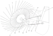
As shown in fig. 3, the finger plate assembly 3 includes a finger plate 31, two adjusting bolts with positive and negative buttons, a finger plate tilting rod 32 and a finger plate height rod 33, one end of the finger plate tilting rod 32 is fixedly connected with a finger plate shaft 38, the other end is hinged with a first adjusting bolt with positive and negative buttons 34, and the other end of the first adjusting bolt with positive and negative buttons 34 is hinged with the frame 1. The finger disc height rod 33 one end is link 36, and the other end is connecting rod 35, forms an contained angle between link 34 and the connecting rod 35, the connecting rod 35 is articulated with the frame, and the link 34 other end is "U" type structure, in the opening of link 34 was arranged in to finger disc axle 38, the bolt passed link and the epaxial through-hole of finger disc and linked together the two, and the second is positive and negative detains adjusting bolt 37 one end and is articulated with connecting rod 35 and link 34 junction, and the other end is articulated with the frame.
The straws are gathered in front of the frame through the finger plate, and preparation is made for subsequent straw picking and smashing work. The first positive and negative buckle adjusting bolt is matched with the finger disc inclined rod, and the finger disc inclined angle can be adjusted by adjusting the first positive and negative buckle adjusting bolt. The second positive and negative buckle adjusting bolt is matched with the finger disc height rod, and the finger disc height can be adjusted by adjusting the positive and negative buckle adjusting bolt.
As shown in fig. 4, the straw picking and smashing mechanism 4 comprises a picking mechanism 41, a smashing mechanism 42 and a straw collecting cover 43, the straw collecting cover 43 is fixed on the frame 1, the picking mechanism 41 and the smashing mechanism 42 are arranged in the straw collecting cover 43, the smashing mechanism 42 is arranged on the upper rear side of the picking mechanism 41, the picking mechanism comprises a picking knife shaft 411, two ends of the picking knife shaft 411 penetrate through the frame 1 and are rotatably connected with the left side and the right side of the frame, and picking claws 412 are arranged on the periphery of the picking knife shaft 411 in a spiral mode. And a third belt pulley sleeved on the second output shaft is in transmission connection with a picking mechanism belt pulley (not shown in the figure) sleeved at the end part of the picking cutter shaft through a belt, so that the picking cutter shaft is driven to rotate, and the picking mechanism works. In the rotating process of the picking cutter shaft, the straw is picked up by the picking claw and is preliminarily crushed.
The crushing mechanism 42 comprises a crushing cutter shaft 421, two ends of the crushing cutter shaft 421 penetrate through the frame 1 and are rotatably connected with the left side and the right side of the frame, and crushing claws 422 are spirally arranged on the periphery of the crushing cutter shaft 421. The first belt pulley 281 sleeved on the first output shaft 28 is in transmission connection with the crushing mechanism belt pulley 423 sleeved on the end part of the crushing cutter shaft 421 through a belt. In the process of the rotation of the smashing cutter shaft, the straw is smashed by the picking claw.
The picking claw and the crushing claw in the attached drawings have the same structure and comprise two positioning pieces 4221, blades 4222 and connecting bolts 4223, the two positioning pieces are fixed on a picking cutter shaft or a crushing cutter shaft, one end of each of three or more blades is arranged between the two positioning pieces, and the connecting bolts penetrate through the two positioning pieces and the blades to connect the two positioning pieces and the blades. The free ends of the blades on both outer sides of the plurality of blades on each of the pickup claws or the crushing claws are bent outward.
A transverse straw feeding port 431 penetrating through the whole machine frame is formed below the straw collecting cover 43, straw discharging ports (not shown in the figure) are formed in the left side and the right side of the upper surface of the straw collecting cover 43, a row of fixed knives 432 facing the picking mechanism are fixed on the front edge of the straw feeding port 431 below the straw collecting cover, two rows of fixed knives 432 are fixed on the rear edge of the straw feeding port, the front row of fixed knives face the front, the rear row of fixed knives face the rear, and the positions of the fixed knives face gaps between the picking claw and the picking claw or between the crushing claw and the crushing claw. The straw is picked up from the straw feeding port and is sucked away by the self-suction fan after being crushed. The fixed knife is arranged between the picking claw and the picking claw or between the crushing claw and the crushing claw. Can carry on spacingly to the straw, it is fixed, make to pick up or smash the process effect better.
As shown in fig. 1 and 2, the straw returning mechanism 5 includes a self-suction blower 51, a conveying pipeline 52, an auger (not shown in the figure) in an outer cover of the auger, an outer cover 53 of the auger, a straw gathering cover 54, an auger driving mechanism, and a straw pressing roller device 57. The self-suction fan 51 is fixed on the front part of the frame 1, the inlet of the self-suction fan 54 is communicated with the straw discharge port of the straw picking and smashing mechanism through a pipeline, the input shaft of the self-suction fan 51 is sleeved with a fan belt pulley 55, and a second belt pulley 282 on one side of the frame or a fourth belt pulley (not shown in the figure) on the other side of the frame drives the fan belt pulley 55 to rotate through a belt. From inhaling 50 one ends of fan 51 export fixed connection pipeline, pipeline 50 extends backward, and the other end is arranged in the straw and is gathered together in the cover 54, the straw gathers together the cover 54 preceding be screw feeder dustcoat 53, and the straw gathers together cover 54 and screw feeder dustcoat 53 and is linked together, is equipped with fore-and-aft screw feeder in screw feeder dustcoat 53, and the screw feeder transmission shaft passes through the bearing to be fixed in screw feeder dustcoat 53. The straw is conveyed to the back by the conveying pipeline 52, and then the straw put into the straw gathering cover enters the auger outer cover.
Screw feeder actuating mechanism includes hydraulic motor 56 (this application still includes the hydraulic pump, pipeline, heat transfer ware and the oil tank that prior art is used commonly and hydraulic motor supporting use commonly used, drive shaft 561, first bevel gear 562, second bevel gear 563, the bearing frame is transversely installed on the frame at drive shaft 561 both ends, hydraulic motor 56 fixes in the frame, hydraulic motor 56's output shaft and drive shaft 561 one end are connected, respectively install first bevel gear 562 at the both ends of drive shaft 561, first bevel gear 562 meshes with second bevel gear 563 on the screw feeder transmission shaft. The straw pressing roller device 57 comprises a straw pressing roller frame 571, a straw pressing roller 572 and a spring 573, the lower part of the rear surface of the auger outer cover is connected with the straw pressing roller frame 571 through a connecting beam 576, the straw pressing roller frame 571 comprises an upper screw rod 574 and an inverted U-shaped frame 575 fixedly connected with the lower end of the screw rod 574, the spring 573 is sleeved on the screw rod 574, the upper end of the screw rod penetrates through the connecting beam and is locked by a nut, and the inverted U-shaped frame 575 is rotatably connected with the left side and the right side of a shaft of the straw pressing roller 572.
By the kibbling straw being inhaled from inhaling formula fan and having been up, carry backward through pipeline, put into the straw through pipeline's export and gather together the cover in, because of auger dustcoat part is below the straw gathers together the cover down, and the two is linked together, in the auger dustcoat, drive the straw by the auger again and discharge downwards until following auger dustcoat lower extreme (auger dustcoat lower extreme opening, the straw discharge port promptly), then discharge in the furrow that the ridging plough was opened, the soil that falls back after ditching through the ridging plough covers the straw, and through the soil suppression of straw suppression roller device above to straw and cover. Thus, the aim of guiding the straws into the furrows can be fulfilled. The seeding and the fertilization are not influenced, and the straws are converted into organic matters to be absorbed by crops after long-time fermentation.
The rotary tilling mechanism 6 comprises two rotary tillers (below the frame, not shown in the figure), the shaft of the first rotary tiller is connected at one end to the output shaft of the first side box 26 and at the other end to the frame, and the shaft of the second rotary tiller is connected at one end to the output shaft of the second side box 27 and at the other end to the frame. The rotary cultivator can be used for carrying out rotary tillage operation on the soil.
As shown in fig. 2, the ridging mechanism 7 is composed of a plurality of ridging assemblies, and the ridging assemblies are composed of ridging plows 71 and ridging plow frames 72 and are ridging through the ridging plows. The ridging plow frame 72 is installed on a cross beam at the rear end of the machine frame, the ridging plow frame 72 is composed of a vertical plate 73 and a U-shaped frame 74 with an opening facing the ridging plow, a hole is formed in the U-shaped frame 74, a plurality of holes are formed in a plow handle 75 of the ridging plow 71, the plow handle is arranged in the U-shaped frame, and a bolt penetrates through the hole in the U-shaped frame and the hole in the plow handle to connect the hole and the plow handle. The depth of the plowing of the ridging plough can be adjusted through the U-shaped frame and the holes on the plough handle. The ridging plough in this application drawing is five, and wherein two are installed respectively in the front of screw feeder dustcoat, and the third is installed in the centre of two screw feeder dustcoats, and the outside at the screw feeder dustcoat is installed respectively to the fourth fifth. The plough handle is provided with a plurality of longitudinal bolt holes, and the ridging plough frame selects the bolt holes with different heights according to the requirement of the ridge depth.
As shown in fig. 1, the spraying mechanism 8 further comprises a spraying mechanism 8, the spraying mechanism 8 comprises a medicine box 81, a high-pressure spray pump, a pipeline 83 and a sprayer 84, the medicine box 81 is fixed on the upper portion of the rack, the outlet of the medicine box 81 is connected with the inlet of the high-pressure spray pump through the pipeline 83, the outlet of the high-pressure spray pump is divided into two branches, the two branches are respectively connected with the sprayer through pipelines, and the two sprayers are respectively inserted into the screw feeder housing. And a fifth belt pulley is mounted on an output shaft at the rear end of the second gearbox, a sixth belt pulley is mounted on an input shaft of the high-pressure spray pump, and the fifth belt pulley and the sixth belt pulley are in belt transmission. The pesticide spraying mechanism sprays pesticide into the straws, so that the straw corrosion process is accelerated, and the plant diseases and insect pests can be prevented.
As shown in fig. 2, the rear end of the frame 1 is rotatably connected to a press roller 92 by a press roller connecting beam 91 which is formed by a front V-shaped beam 93 and a rear straight beam 94 which are hinged to each other. The V-shaped beam in front is fixedly connected with the rear end of the frame, and the straight beam is connected with the press roller.
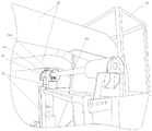
As shown in fig. 5, a first pinch roller mechanism 10, a second pinch roller mechanism 20 and two connecting plates 30 are mounted on both side surfaces of a frame 1, the first pinch roller mechanism 10 includes two first bending plates 101, first pinch rollers 102 and first springs 103, the lower ends of the two first bending plates 101 are connected through first connecting rods 104, the bending positions of the two first bending plates 101 are provided with holes, first bolts 105 penetrate through the two holes to be rotatably connected with the first bending plates, one end of each first spring 103 is sleeved on the corresponding first connecting rod, the other end of each first spring is sleeved on the frame, two ends of a shaft of each first pinch roller are rotatably connected with the other ends of the two first bending plates, and the first pinch roller is arranged on a belt between the first belt pulley and a crushing mechanism belt pulley or a belt between the third belt pulley and a picking mechanism belt pulley;
the second pinch roller mechanism 20 comprises two second bending plates 201, a second pinch roller 202 and a second spring 203, the lower ends of the two second bending plates 201 are connected through a second connecting rod, the bending positions of the two second bending plates are provided with holes, a second bolt 204 penetrates through the two holes to be rotatably connected with the second bending plates, two shaft ends of the second pinch roller are rotatably connected with the upper ends of the two second bending plates, one end of the second spring is sleeved on the first screw rod, the other end of the second spring is sleeved on the second connecting rod, and the second pinch roller is arranged on a second belt pulley or a belt between a fourth belt pulley and a fan belt pulley;
the two connecting plates 30 are respectively arranged on the outer sides of the two first bending plates, the lower ends of the two connecting plates are sleeved on the first bolts, the two connecting plates are arranged on the outer sides of the two second bending plates, and the upper ends of the two connecting plates are sleeved on the second bolts. The tightness of the belt can be adjusted through the first pressing wheel mechanism and the second pressing wheel mechanism.
The working process is as follows:
1. the power transmission tractor passes through the power input shaft with power, first transmission shaft transmits power for first gearbox, and the first output shaft and the second output shaft of first gearbox drive rubbing crusher structure and pickup mechanism operation respectively, and first gearbox passes through the second transmission shaft and transmits power for the second gearbox, and the second gearbox transmits power for first limit case and second limit case, and first limit case and second limit case drive first rotary cultivator and second rotary cultivator operation respectively.
2. Gathering the straws:
adjust first positive and negative knot adjusting bolt and second positive and negative knot adjusting bolt as required, adjust the height and the inclination of finger dish. In the advancing process of the comprehensive operation machine, the finger disc gathers the straws to the front of the frame, and preparation is made for subsequent picking and crushing.
3. The picking and crushing process of the straws:
the straw is picked up through the picking mechanism, is primarily crushed and then is thrown backwards, the crushing mechanism performs secondary crushing on the straw, and the crushed straw is sucked away by the self-suction fan.
4. Returning the straws to the field:
straw that is inhaled away by self-priming fan passes through conveying pipe and carries backward, put in straw gathering cover because of the pipeline rear end, so the straw is thrown into the straw and gathers up in the cover, under the effect of screw feeder transmission shaft, the straw is carried downwards, and then arranged in the soil, because of two preceding ridging ploughs that all have of screw feeder dustcoat lower extreme, so the straw is thrown into in the ridge that the ridging plough has just been played, and then is covered by the soil that falls back, after being suppressed by straw suppression roller again, the straw is buried in the furrow.
5. Spraying medicine
The straws are guided into the ridge stirring outer cover, and after being sprayed by the spraying mechanism, the medicines and the straws are mixed and then are discharged into the furrows.
6. Rotary tillage, ridging and pressing
Before the ridging plough performs ridging, the rotary cultivator performs rotary tillage. And the ridging plough is used for ridging the rotary-tilled soil. After ridging, the ridge is pressed by a press roller. And finishing the operation.