Disclosure of Invention
Aiming at the defects of limited operation height, complex operation and high requirements on personnel physical strength and devices in the existing site operation, the invention provides the connecting device for the insulating rod indirect live bypass cable and the live wire, which can achieve the following technical effects: only 1 ground operation personnel can easily hang the device into live wire and be suitable for all height's poles, has enlarged mountain area live working coverage and has also alleviateed intensity of labour, has promoted the operating efficiency simultaneously.
In order to achieve the purpose, the invention provides the following technical scheme: an indirect electrified bypass cable and electrified lead connecting device of an insulating rod comprises an insulating operating rod, wherein a cable clamp used for being fixed with an electrified lead is arranged at the head end of the insulating operating rod, a hoop used for fixing the bypass cable is arranged at the tail end of the insulating operating rod, a yoke plate is arranged on the cable clamp, the bypass cable is fixed in the hoop, and the head of the bypass cable is connected with the yoke plate; the wire clamp comprises a movable clamp capable of being opened or closed, a safety device and an unlocking ring are arranged on the movable clamp, the live wire touches the safety device to close the movable clamp, and the unlocking ring is pulled to unlock the safety device to open the clamp; the device is characterized by further comprising a pulley wound with an insulating lifting rope, wherein a rope fixing mechanism used for fixing the insulating lifting rope is arranged on the insulating operating rod, and the end part of the insulating lifting rope is fixed on the rope fixing mechanism so that the insulating operating rod is fixed on the insulating lifting rope.
Through this technical scheme, at first lay bypass cable in the operation point below, operating personnel climbs the pole and hangs the pulley that has insulating lifting rope into electrified wire after on the pole, and ground operating personnel fixes bypass cable's head on the yoke plate and carries out electric connection with the fastener to fix bypass cable through the staple bolt. And then the insulating operating rod is fixed on the insulating lifting rope through a rope fixing mechanism. Ground operating personnel buckle safeties and open the movable clamp to the movable clamp, when pulling insulating lifting rope and lift by crane the fastener that has the bypass cable to electrified wire, open movable clamp aims at electrified wire, and ground operating personnel drop down the bypass cable and make electrified wire touch safeties in the movable clamp to make the movable clamp press from both sides the clamp and take the electric wire, thereby can carry out live working. After the live-line work is finished, the working personnel on the rod stretch into the unlocking ring by using the insulating rod to pull the unlocking ring so as to unlock the safety device, so that the movable clamp is in an open state so as to be separated from a live-line wire, and the wire clamp with the bypass cable is put down by using the insulating lifting rope under the cooperation of ground working personnel. Only 1 ground operation personnel can easily hang the whole device into the live wire and be suitable for all height poles, and the mountain area live working coverage is enlarged, the labor intensity is reduced, and the operation efficiency is improved.
The invention is further configured to: the hoop comprises a fixing ring, a movable ring and a locking bolt, the movable ring is hinged to the fixing ring, and the movable ring and the fixing ring are fixed through the locking bolt. Through this setting, the movable ring is rotatable to be opened relatively solid fixed ring, and the movable ring is closed to the back in the bypass cable is put into the fixed ring to locking bolt locking, bypass cable just tightly is pressed from both sides tightly this moment in the staple bolt, follows insulating bar and goes up and down together, and is fixed firm, adapts to the bypass cable of different pipe diameters.
The invention is further configured to: the lower end of the movable clamp is provided with a fixing part, and the fixing part is sleeved at the head end of the insulating operating rod. Through this setting, fastener and insulating bar are detachable construction, conveniently change the fastener, can divide the body to transport simultaneously, portable.
The invention is further configured to: the head of the bypass cable is fixed on the yoke plate through a fixing bolt. Through this setting, the head fastening of bypass cable is on the yoke plate, realizes being connected with the electrified of fastener, guarantees that the circular telegram performance is stable.
The invention is further configured to: the yoke plate is fixed on the wire clamp through a fastening bolt. Through this setting, yoke plate and fastener are detachable construction, and both are connected reliably, and the contact is good.
The invention is further configured to: the rope fixing mechanism comprises a hanging ring and an openable hanging buckle, the hanging ring is fixed at the tail end of the insulating operating rod, and the hanging buckle is buckled on the hanging ring. Through this setting, rings are fixed on insulating bar, penetrate the couple of opening with the one end of insulating lifting rope in, then on the couple of opening colludes into rings again to wind insulating lifting rope on insulating bar, make insulating bar when lifting by crane, the fastener is in the upper end all the time, and the operation of being convenient for is fixed or is separated with electrified wire.
The invention is further configured to: the hanging buckle is provided with a protective sleeve, and the protective sleeve closes the opened hanging buckle. Through this setting, have the fixed back of hanging of insulating lifting rope to detain, the instrument that closed protective sheath can prevent to hang in falls out, improves the security.
The invention has the advantages that: firstly, lay the bypass cable in the operating point below, the pole is gone up the operation personnel and is climbed the pole and hang into electrified wire the pulley that has insulating lifting rope after, ground operation personnel fix the head of bypass cable on the yoke plate and carry out electric connection with the fastener to fix the bypass cable through the staple bolt. And then the insulating operating rod is fixed on the insulating lifting rope through a rope fixing mechanism. Ground operating personnel buckle safeties and open the movable clamp to the movable clamp, when pulling insulating lifting rope and lift by crane the fastener that has the bypass cable to electrified wire, open movable clamp aims at electrified wire, and ground operating personnel drop down the bypass cable and make electrified wire touch safeties in the movable clamp to make the movable clamp press from both sides the clamp and take the electric wire, thereby can carry out live working. After the live-line work is finished, the working personnel on the rod stretch into the unlocking ring by using the insulating rod to pull the unlocking ring so as to unlock the safety device, so that the movable clamp is in an open state so as to be separated from a live-line wire, and the wire clamp with the bypass cable is put down by using the insulating lifting rope under the cooperation of ground working personnel. Only 1 ground operation personnel can easily hang the whole device into the live wire and be suitable for all height poles, and the mountain area live working coverage is enlarged, the labor intensity is reduced, and the operation efficiency is improved.
Detailed Description
In the description of the present embodiment, it should be noted that, as the terms "center", "upper", "lower", "left", "right", "vertical", "horizontal", "inner", "outer", "front", "rear", etc. appear, their indicated orientations or positional relationships are based on those shown in the drawings, and are only for convenience of describing the present invention and simplifying the description, but do not indicate or imply that the referred device or element must have a specific orientation, be constructed and operated in a specific orientation, and thus, should not be construed as limiting the present invention. Furthermore, the terms "first," "second," and "third" as appearing herein are used for descriptive purposes only and are not to be construed as indicating or implying relative importance.
The invention is further described with reference to the drawings and the specific embodiments in the following description.
Example (b):
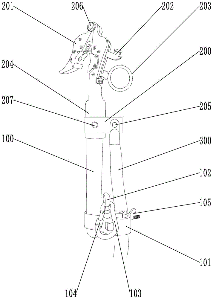
as shown in fig. 1, 2 and 3, an indirect live bypass cable 300 and live conductor connecting device with an insulating rod comprises an insulating operating rod 100, wherein a wire clamp for fixing the live conductor is arranged at the head end of the insulating operating rod 100, a hoop 101 for fixing the bypass cable 300 is arranged at the tail end of the insulating operating rod 100, a yoke plate 200 is arranged on the wire clamp, the bypass cable 300 is fixed in the hoop 101, and the head of the bypass cable 300 is connected with the yoke plate 200; the wire clamp comprises a movable clamp 201 which can be opened or closed, wherein a safety device 202 and an unlocking ring 203 are arranged on the movable clamp 201, a live wire touches the safety device 202 to close the movable clamp 201, and the unlocking ring 203 is pulled to unlock the safety device 202 to open the clamp; the insulating lifting rope fixing device is characterized by further comprising a pulley wound with an insulating lifting rope, a rope fixing mechanism used for fixing the insulating lifting rope is arranged on the insulating operating rod 100 and comprises a hanging ring 102 and a hanging buckle 103 capable of being opened, the hanging ring 102 is fixed at the tail end of the insulating operating rod 100, the hanging buckle 103 is buckled on the hanging ring 102, a protective sleeve 104 is arranged on the hanging buckle 103, the hanging buckle 103 which is opened is closed by the protective sleeve 104, and the end portion of the insulating lifting rope is fixed on the rope fixing mechanism so that the insulating operating rod 100 is fixed on the insulating lifting rope.
In this embodiment, bypass cable 300 has first been laid to the operating point below, and after the pole operating personnel climbed the pole and hung the pulley that has insulating lifting rope into electrified wire, ground operating personnel fixed bypass cable 300's head on yoke plate 200 and carried out electric connection with the fastener to fix bypass cable 300 through staple bolt 101. One end of the insulated lifting rope penetrates into the opened hook, then the opened hook is hooked into the hanging ring 102, and the insulated lifting rope is wound on the insulated operating rod 100, so that the wire clamp is always positioned at the upper end of the insulated operating rod 100 during lifting, and the insulated operating rod 100 is convenient to operate and fix or separate with an electrified wire. After the hanging buckle 103 with the insulated lifting rope is fixed, the closed protective sleeve 104 can prevent the hung tools from falling out, and the safety is improved. Ground operating personnel buckle the safety device 202 on the movable clamp 201 and open the movable clamp 201, when pulling the insulated lifting rope to lift the wire clamp with the bypass cable 300 to the live conductor, the opened movable clamp 201 is aligned with the live conductor, the ground operating personnel pull down the bypass cable 300 to enable the live conductor to touch the safety device 202 in the movable clamp 201, so that the movable clamp 201 clamps the live conductor, and the live operation can be carried out. After the live working is completed, the worker on the pole extends the unlocking ring 203 with an insulating rod to pull the unlocking ring 203 to unlock the safety device 202, so that the movable clamp 201 is in an open state to be separated from the live conductor, and the wire clamp with the bypass cable 300 is put down through the insulating lifting rope in cooperation with the ground worker. Only 1 ground operation personnel can easily hang the whole device into the live wire and be suitable for all height poles, and the mountain area live working coverage is enlarged, the labor intensity is reduced, and the operation efficiency is improved.
Specifically, the hoop 101 includes a fixing ring, a movable ring and a locking bolt 105, the movable ring is hinged to the fixing ring, and the movable ring and the fixing ring are fixed by the locking bolt 105. The movable ring can be opened in a rotating mode relative to the fixing ring, after the bypass cable 300 is placed into the fixing ring, the movable ring is closed and locked through the locking bolt 105, the bypass cable 300 is tightly clamped in the hoop 101 and goes up and down along with the insulating operating rod 100, fixing is firm, and the bypass cable 300 is suitable for bypass cables 300 with different pipe diameters.
The lower extreme of activity anchor clamps 201 is equipped with fixed part 204, and the fixed part 204 cover is established at the head end of insulating bar 100, and fastener and insulating bar 100 are detachable construction, conveniently change the fastener, can separate the body transportation simultaneously, portable.
The head of the bypass cable 300 is fixed on the yoke plate 200 through the fixing bolt 205, and the head of the bypass cable 300 is fastened on the yoke plate 200, so that the live connection with a wire clamp is realized, and the stability of the electrifying performance is ensured. The yoke plate 200 is fixed on the wire clamp through the fastening bolt 207, and the yoke plate 200 and the wire clamp are of detachable structures and are reliably connected and have good contact.
In a more specific embodiment, the device is mainly composed of the following components.
Insulating operation rod 100: the outer diameter is phi 30 mm, the length is 800 mm, and the tail ends are fastened and connected into a whole by an aluminum ring.
The movable clamp 201: the aluminum alloy is made of two concave clamps, and the clamping live wire preventing device falls off when the movable clamp 201 is tightened. The movable clamp 201 has the following model: 50 square millimeters, 70 square millimeters, 120 square millimeters, 150 square millimeters, 185 square millimeters, 240 square millimeters cross-sectional area, the movable clamp 201 is changed into the mould of corresponding model according to electrified wire type number, makes movable clamp 201 and electrified wire contact connection inseparabler, and the conduction current is more enlarged.
The connecting bolt 206: the performance grade 4.8 bolt is used for connecting two clamps, and the two clamps can be separated by external force with the connecting bolt 206 as a fulcrum.
Fixing part 204: the inner diameter is 30 mm, the upper end is an integral aluminum structure, and the lower end is connected with an insulating operating rod 100 with the outer diameter of 30 mm.
The safety device 202: made of aluminum alloy, the up-and-down state of the safety device 202 controls the tightening and loosening state of the movable clamp 201.
Unlocking ring 203: the movable clamp 201 is in a state of tightly fastening the live conductor when the movable clamp 201 clamps the live conductor, and the movable clamp 201 is in a state of tightly fastening the live conductor after the movable clamp 201 pulls the safety device 202 downwards through the unlocking ring 203 to separate, and the movable clamp 201 is in a state of releasing the separated conductor.
The yoke plate 200: the connecting plate is made of a tinned copper plate with the length of 75 mm, the width of 40 mm and the thickness of 4 mm, two ends of the connecting plate 200 are respectively provided with a screw hole with the diameter of 10 mm, and the distance between the two holes is 50 mm.
Fastening bolts 207: the clamp is made of ferrous materials with the outer diameter of phi 10 mm, the length of 30 mm and the performance level of 4.8, the clamp is fixed on the tinned copper connecting plate 200 by using the fastening bolt 207, the connection is reliable, and the contact is good.
Fixing the bolt 205: the outer diameter is phi 10 mm, the length is 30 mm, and the performance level is 4.8, so that the head of the bypass cable 300 is fixed on the tinned copper connecting plate 200, the connection is reliable, and the contact is good.
Bypass cable 300: is a flexible high-voltage power cable. The temporary bypass power supply cable line consists of a bypass load switch, a cable and a quick bypass connector, and is quickly connected into a temporary bypass power supply cable line on site.
And (4) hoop 101: the inner diameter is 30 mm, one end of which is fixed with the insulating operating rod 100 and the other end is fixed with the bypass cable 300.
Locking bolts 105: the bypass cable 300 is placed into the hoop 101 at a proper position and then the locking bolt 105 of the hoop 101 is tightened, so that the bypass cable 300 is fixed in the hoop 101.
Hanging ring 102: a hoisting ring 102 with a screw rod with the specification of phi 10 mm and 50 mm penetrates into a screw hole in the middle of the insulating operating rod 100 and the hoop 101, and a nut is screwed.
Hanging and buckling 103: the oval shape is made of steel with the diameter of 6 mm, and a protective sleeve 104 is arranged outside the connecting part to prevent the hung tool from falling out.
The above embodiments are described in detail for the purpose of further illustrating the present invention and should not be construed as limiting the scope of the present invention, and the skilled engineer can make insubstantial modifications and variations of the present invention based on the above disclosure.