CN114130478B - Building rubbish breaker - Google Patents

Building rubbish breaker Download PDF

Info

Publication number
CN114130478B
CN114130478B CN202111322322.4A CN202111322322A CN114130478B CN 114130478 B CN114130478 B CN 114130478B CN 202111322322 A CN202111322322 A CN 202111322322A CN 114130478 B CN114130478 B CN 114130478B
Authority
CN
China
Prior art keywords
case
stirring device
fixed
construction waste
driving
Prior art date
Legal status (The legal status is an assumption and is not a legal conclusion. Google has not performed a legal analysis and makes no representation as to the accuracy of the status listed.)
Active
Application number
CN202111322322.4A
Other languages
Chinese (zh)
Other versions
CN114130478A (en
Inventor
王春
Current Assignee (The listed assignees may be inaccurate. Google has not performed a legal analysis and makes no representation or warranty as to the accuracy of the list.)
Jiangsu Tianqin Environmental Technology Co ltd
Original Assignee
Jiangsu Tianqin Environmental Technology Co ltd
Priority date (The priority date is an assumption and is not a legal conclusion. Google has not performed a legal analysis and makes no representation as to the accuracy of the date listed.)
Filing date
Publication date
Application filed by Jiangsu Tianqin Environmental Technology Co ltd filed Critical Jiangsu Tianqin Environmental Technology Co ltd
Priority to CN202111322322.4A priority Critical patent/CN114130478B/en
Publication of CN114130478A publication Critical patent/CN114130478A/en
Application granted granted Critical
Publication of CN114130478B publication Critical patent/CN114130478B/en
Active legal-status Critical Current
Anticipated expiration legal-status Critical

Links

Images

Classifications

    • B—PERFORMING OPERATIONS; TRANSPORTING
    • B02—CRUSHING, PULVERISING, OR DISINTEGRATING; PREPARATORY TREATMENT OF GRAIN FOR MILLING
    • B02C—CRUSHING, PULVERISING, OR DISINTEGRATING IN GENERAL; MILLING GRAIN
    • B02C13/00—Disintegrating by mills having rotary beater elements ; Hammer mills
    • B02C13/20—Disintegrating by mills having rotary beater elements ; Hammer mills with two or more co-operating rotors
    • B—PERFORMING OPERATIONS; TRANSPORTING
    • B02—CRUSHING, PULVERISING, OR DISINTEGRATING; PREPARATORY TREATMENT OF GRAIN FOR MILLING
    • B02C—CRUSHING, PULVERISING, OR DISINTEGRATING IN GENERAL; MILLING GRAIN
    • B02C13/00—Disintegrating by mills having rotary beater elements ; Hammer mills
    • B02C13/26—Details
    • B02C13/28—Shape or construction of beater elements
    • B02C13/2804—Shape or construction of beater elements the beater elements being rigidly connected to the rotor
    • B—PERFORMING OPERATIONS; TRANSPORTING
    • B02—CRUSHING, PULVERISING, OR DISINTEGRATING; PREPARATORY TREATMENT OF GRAIN FOR MILLING
    • B02C—CRUSHING, PULVERISING, OR DISINTEGRATING IN GENERAL; MILLING GRAIN
    • B02C13/00—Disintegrating by mills having rotary beater elements ; Hammer mills
    • B02C13/26—Details
    • B02C13/286—Feeding or discharge
    • B—PERFORMING OPERATIONS; TRANSPORTING
    • B02—CRUSHING, PULVERISING, OR DISINTEGRATING; PREPARATORY TREATMENT OF GRAIN FOR MILLING
    • B02C—CRUSHING, PULVERISING, OR DISINTEGRATING IN GENERAL; MILLING GRAIN
    • B02C13/00—Disintegrating by mills having rotary beater elements ; Hammer mills
    • B02C13/26—Details
    • B02C13/30—Driving mechanisms
    • B—PERFORMING OPERATIONS; TRANSPORTING
    • B02—CRUSHING, PULVERISING, OR DISINTEGRATING; PREPARATORY TREATMENT OF GRAIN FOR MILLING
    • B02C—CRUSHING, PULVERISING, OR DISINTEGRATING IN GENERAL; MILLING GRAIN
    • B02C13/00—Disintegrating by mills having rotary beater elements ; Hammer mills
    • B02C13/26—Details
    • B02C13/286—Feeding or discharge
    • B02C2013/28609—Discharge means
    • Y—GENERAL TAGGING OF NEW TECHNOLOGICAL DEVELOPMENTS; GENERAL TAGGING OF CROSS-SECTIONAL TECHNOLOGIES SPANNING OVER SEVERAL SECTIONS OF THE IPC; TECHNICAL SUBJECTS COVERED BY FORMER USPC CROSS-REFERENCE ART COLLECTIONS [XRACs] AND DIGESTS
    • Y02—TECHNOLOGIES OR APPLICATIONS FOR MITIGATION OR ADAPTATION AGAINST CLIMATE CHANGE
    • Y02W—CLIMATE CHANGE MITIGATION TECHNOLOGIES RELATED TO WASTEWATER TREATMENT OR WASTE MANAGEMENT
    • Y02W30/00—Technologies for solid waste management
    • Y02W30/50—Reuse, recycling or recovery technologies
    • Y02W30/58—Construction or demolition [C&D] waste

Landscapes

  • Engineering & Computer Science (AREA)
  • Food Science & Technology (AREA)
  • Mixers Of The Rotary Stirring Type (AREA)

Abstract

The invention discloses a construction waste crushing device, which relates to the field of construction waste, and the device comprises a case and also comprises: the stirring device is movably arranged in the case and is used for stirring and crushing the construction waste in the case; the chute devices are arranged on two end parts of the stirring device and are used for motion guidance when the stirring device moves; the auxiliary stirring device is movably arranged on the side wall of the case and is used for further crushing the construction waste crushed by the stirring device; the driving mechanism is arranged on the side wall of the case, one end parts of the stirring device and the auxiliary stirring device are connected with the driving mechanism, and the driving mechanism is used for driving the auxiliary stirring device to rotate in the case.

Description

Building rubbish breaker
Technical Field
The invention relates to the field of construction waste, in particular to a construction waste crushing device.
Background
The construction waste refers to the general name of dregs, waste concrete, waste bricks and stones and other wastes produced by people in the production activities of the construction industry such as demolition, construction, decoration and repair. The construction waste can be classified into engineering residue soil, decoration waste, demolition waste, engineering slurry and the like according to the production source; the construction waste can be classified into slag, concrete blocks, broken stone blocks, broken bricks and tiles, waste mortar, slurry, asphalt blocks, waste plastics, waste metals, waste bamboo and wood and the like according to the composition. The construction waste comprises waste residue soil, waste soil, sludge, waste materials and the like. These materials are not helpful to the construction itself, but are substances generated in the construction process, and need to be treated correspondingly, so that the ideal engineering project construction can be achieved, and because the materials are an integral process, the link consideration is more important.
The construction waste needs to be stirred and crushed in the treatment process due to the characteristics of the construction waste; however, the existing device adopts a unidirectional stirring type crushing mode, and the position of the stirring rod device is fixed, so that large stone rubbish is easily blocked at the edge part, and the device fails.
Disclosure of Invention
The invention aims to provide a construction waste crushing device, and aims to solve the problems that an existing construction waste crushing device is single in stirring mode when used for stirring and crushing construction waste, and poor in stability during working.
In order to achieve the purpose, the invention provides the following technical scheme:
the utility model provides a construction waste breaker, includes quick-witted case, still includes:
the stirring device is movably arranged in the case and is used for stirring and smashing the construction waste in the case;
the chute devices are arranged on two end parts of the stirring device and are used for carrying out motion guidance when the stirring device moves;
the auxiliary stirring device is movably arranged on the side wall of the case and is used for further crushing the construction waste crushed by the stirring device;
the driving mechanism is arranged on the side wall of the case, one end parts of the stirring device and the auxiliary stirring device are connected with the driving mechanism, and the driving mechanism is used for driving the auxiliary stirring device to rotate in the case and simultaneously driving the stirring device to realize multi-degree-of-freedom rotary stirring and crushing in the case.
On the basis of the technical scheme, the invention also provides the following optional technical scheme:
in one alternative: agitating unit includes the horizontal pole, and fixed mounting has the vertical pole on the horizontal pole, and the side position vertical fixation of horizontal pole has the ringlet, and the side position vertical fixation of vertical pole has big ring, a tip of horizontal pole with actuating mechanism is connected, just the spout device is installed on the both ends of vertical pole.
In one alternative: the sliding groove device comprises a middle groove, a protrusion is arranged in the middle of the middle groove, a sliding block is attached to the surface of the protrusion, and one end of the longitudinal rod is connected with the sliding block.
In one alternative: the auxiliary stirring device comprises a rotating shaft which is rotatably arranged on the case, an outer rod is fixed on the rotating shaft, rotating rods are uniformly arranged on the side edge parts of the outer rod, protrusions are fixed on the surfaces of the rotating rods, and one end part of the rotating shaft is connected with the driving mechanism.
In one alternative: the driving mechanism comprises a driving element and a connecting member for driving the cross rod to rotate in the case, a thread plate device is arranged on the side wall of the case, the driving element is installed on the thread plate device, one end of the connecting member is connected with one end of the driving device, and the other end of the connecting member is connected with the cross rod.
In one alternative: the connecting elements is installed including rotating pivot on the machine case, and the sleeve pipe has been cup jointed to driven element's output, the pivot is pegged graft and is installed sheathed tube inside, be fixed with the bearing frame device between pivot and the machine case, the end of pivot is rotated and has been cup jointed the cover card, the fixed surface of cover card has the sketch plate, a tip of horizontal pole is installed on the sketch plate, a tip of pivot pass through connecting element with the axis of rotation is connected.
In one alternative: the improved cabinet is characterized in that the cabinet comprises round corners, arc-shaped inner containers are arranged at the inner corners of the cabinet, a feed inlet is arranged at the middle part of the top of the cabinet, an inner groove is formed in the cabinet, a discharge outlet is formed in the middle part of the cabinet, a base is fixed on the side edge of the bottom of the cabinet, and a second discharge outlet is formed in the middle part of the bottom of the cabinet.
In one alternative: the bearing seat device comprises a bearing, and an outer bolt is installed between the side part of the bearing seat device and the case in a threaded mode.
In one alternative: the top of the discharge port is fixed with a bottom plate, foundation bolts are inserted into the bottom plate, and a support is fixed to the top of the bottom plate.
Compared with the prior art, the invention has the following beneficial effects:
the device has the function of stirring at any angle through the profiling improved design of the universal shaft. The side part of the case is fixed with a thread plate device, and the top of the thread plate device is fixed with a motor, so that the stability of fixing the motor can be ensured. The output end of the motor is sleeved with the sleeve, and the stability of the output power of the output shaft can be ensured by passing. The telescopic inside grafting install the pivot, is fixed with the bearing frame device between pivot and the quick-witted case, and the end of pivot is rotated and has been cup jointed the cover card, and the fixed surface of cover card has the dysmorphism board, and the effect of setting up the dysmorphism board is mainly with universal device slope, and then forms multi freedom's stirring effect. The inside agitating unit that pegs graft of side of dysmorphism board has, and agitating unit includes the horizontal pole, and the middle part fixed mounting of horizontal pole has the vertical pole, and horizontal pole and vertical pole are main stirring position. The rib plates are fixed in the middle of the transverse rods and the longitudinal rods and can reinforce the strength of the structure. The side part of the transverse rod is vertically fixed with a small ring, the side part of the longitudinal rod is vertically fixed with a large ring, and the large ring and the small ring are auxiliary stirring equipment. The belt pulley is arranged in the middle of the rotating shaft, the belt is sleeved on the surface of the belt pulley, the auxiliary stirring device is sleeved on the other side of the belt, the auxiliary stirring device is a linkage auxiliary stirring device, single power is utilized, and the linkage effect is achieved.
Drawings
FIG. 1 is a schematic view of the present invention.
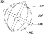
FIG. 2 is a schematic view of the stirring apparatus of the present invention.
Fig. 3 is a schematic structural view of the chute device of the present invention.
FIG. 4 is a schematic structural diagram of an auxiliary stirring device according to another embodiment of the present invention.
Notations for reference numerals: 1 chassis, 101 fillets, 102 arc-shaped liner, 103 feeding ports, 104 inner grooves, 105 discharging ports, 2 thread plate devices, 201 plates, 202 bolts, 203 support rods, 204 support plates, 3 motors, 301 sleeves, 4 bearing seat devices, 401 bearings, 402 outer bolts, 5 rotating shafts, 501 belt pulleys, 6 sleeves, 7 special-shaped plates, 8 stirring devices, 801 cross rods, 802 longitudinal rods, 803 rib plates, 804 large rings, 805 small rings, 9 sliding groove devices, 901 middle grooves, 902 bulges, 10 sliders, 11 supports, 12 bottom plates, 13 anchor bolts, 14 belts, 15 auxiliary stirring devices, 151 rotating shafts, 152 outer rods, 153 rotating rods, 154 bulges, 16 bearing seats, 17 partition plates, 18 second discharging ports and 19 bases.
Detailed Description
In order to make the objects, technical solutions and advantages of the present invention more clearly understood, the present invention is further described in detail below with reference to the accompanying drawings and embodiments; in the drawings or the description, the same reference numerals are used for similar or identical parts, and the shape, thickness, or height of each part may be enlarged or reduced in practical use. The examples are given solely for the purpose of illustration and are not intended to limit the scope of the invention. Any obvious modifications or variations can be made to the present invention without departing from the spirit or scope of the present invention.
In one embodiment, as shown in fig. 2, the construction waste crushing device provided by the present invention includes a chassis 1, and further includes:
the stirring device 8 is movably arranged inside the case 1, and the stirring device is used for stirring and smashing the construction waste in the case 1;
the chute devices 9 are installed on two end parts of the stirring device 8, and the chute devices 9 are used for guiding the movement when the stirring device 8 moves;
the auxiliary stirring device 15 is movably arranged on the side wall of the case 1, and the auxiliary stirring device 15 is used for further crushing the construction waste crushed by the stirring device 8;
the driving mechanism is arranged on the side wall of the case 1, one end parts of the stirring device 8 and the auxiliary stirring device 15 are connected with the driving mechanism, and the driving mechanism is used for driving the auxiliary stirring device 15 to rotate in the case 1 and simultaneously driving the stirring device 8 to realize multi-degree-of-freedom rotary stirring and crushing in the case 1.
When the whole device works, firstly, the construction waste is put into the case 1, then the driving mechanism is started to work, when the driving mechanism works, the stirring device 8 is driven to rotate and stir in the case 1 in multiple degrees of freedom, the construction waste in the case 1 is fully crushed, the construction waste crushed by the stirring device 8 is discharged into the auxiliary stirring device 15, the auxiliary stirring device 15 pulls the building crushed by the stirring device 8 for further crushing treatment, as an embodiment, the left, right, upper and lower positions of all parts shown in the drawing are only an arrangement mode, and the specific positions are set according to specific needs;
in one embodiment, as shown in fig. 1 and fig. 2, the stirring device 8 includes a cross bar 801, a longitudinal bar 802 is fixedly installed on the cross bar 801, a small ring 805 is vertically fixed on a side portion of the cross bar 801, a large ring 804 is vertically fixed on a side portion of the longitudinal bar 802, one end portion of the cross bar 801 is connected with the driving mechanism, and the chute devices 9 are installed on two end portions of the longitudinal bar 802;
when the driving mechanism starts to work, the cross rod 801 is driven to rotate, and when the cross rod 81 rotates, the longitudinal rod 802, the small ring 805 and the large ring 804 are driven to realize multi-degree-of-freedom movement, so that the construction waste in the case 1 is crushed, and the chute device 9 guides the movement in the movement process;
ribs 803 are fixed at the middle parts of the transverse rods 801 and the longitudinal rods 802, and the strength of the transverse rods 801 and the strength of the longitudinal rods 802 are enhanced by the ribs 803.
In one embodiment, as shown in fig. 1 and 3, the sliding groove device 9 includes a middle groove 901, a protrusion 902 is formed in a middle portion of the middle groove 901, a slider 10 is attached to a surface of the protrusion 902, and one end of the longitudinal rod 802 is connected to the slider 10;
in the embodiment of the present invention, when the driving device drives the stirring device 8 to move, one end of the longitudinal rod 802 in the stirring device 8 will move in the middle slot 901 through the sliding block 10, so as to realize swinging;
in one embodiment, as shown in fig. 1 and 4, the auxiliary stirring device 15 includes a rotating shaft 151 rotatably mounted on the chassis 1, an outer rod 152 is fixed on the rotating shaft 151, a rotating rod 153 is uniformly mounted at a side portion of the outer rod 152, a protrusion 154 is fixed on a surface of the rotating rod 153, and one end portion of the rotating shaft 151 is connected to the driving mechanism;
in the embodiment of the present invention, when the driving mechanism starts to operate, the rotating shaft 151 is driven to rotate, and when the rotating shaft 151 rotates, the construction waste is stirred and crushed by the plurality of rotating rods 153 installed on the side wall thereof;
in one embodiment, as shown in fig. 1, the driving mechanism includes a driving element and a connecting member for driving the cross bar 801 to rotate in the chassis 1, a screw plate device 2 is disposed on a side wall of the chassis 1 and the driving element is mounted on the screw plate device, one end of the connecting member is connected to one end of the driving device and the other end of the connecting member is connected to the cross bar 801;
in one embodiment, as shown in fig. 1, the connecting member includes a rotating shaft 5 rotatably mounted on the chassis 1, a sleeve 301 is sleeved on an output end of the driven element, the rotating shaft 5 is inserted into the sleeve 301, a bearing seat device 4 is fixed between the rotating shaft 5 and the chassis 1, a sleeve clamp 6 is rotatably sleeved on an end of the rotating shaft 5, a profiled plate 7 is fixed on a surface of the sleeve clamp 6, one end of the cross rod 801 is mounted on the profiled plate 7, and one end of the rotating shaft 5 is connected to the rotating shaft 151 through a connecting element;
when the driving element starts to work, the rotating shaft 151 is driven to rotate through the connecting element, meanwhile, the rotating shaft 5 is driven to rotate when the driving element works, the special-shaped plate 7 is driven to rotate when the rotating shaft 5 rotates, one side of the special-shaped plate 7 upwards tilts, and the transverse rod 801 can rotate at a certain angle in the rotating process, so that stirring is realized in the rotating process of the transverse rod 801, and the longitudinal rod 802 swings in a matching manner, so that the stirring and crushing effects with multiple degrees of freedom can be realized;
the driving element can be set as a rotating motor or a pneumatic motor, etc., and is preferably set as a motor 3 in the embodiment;
in one embodiment, as shown in fig. 1, the case 1 includes a rounded corner 101, an arc-shaped inner container 102 is disposed at an inner corner of the case 1, a feed inlet 103 is disposed at a middle portion of a top of the case 1, an inner groove 104 is disposed inside the case 1, a discharge outlet 105 is disposed at a middle portion of the case 1, a base 19 is fixed to a side edge of a bottom of the case 1, and a second discharge outlet 18 is disposed at a middle portion of a bottom of the case 1;
in one embodiment, as shown in fig. 1, the bearing seat device 4 includes a bearing 401, and an external bolt 402 is threadedly mounted between a side portion of the bearing seat device 401 and the chassis 1;
in one embodiment, as shown in fig. 1, a bottom plate 12 is fixed on the top of the discharging hole 105, an anchor bolt 13 is inserted into the bottom plate 12, and a bracket 11 is fixed on the top of the bottom plate 12;
a partition 17 is fixed at the bottom of the discharge port 105.
When the whole device is put into use, the thread plate device 2 is fixed at the side part of the case 1, and the thread plate device 2 is arranged to ensure that the motor at the top can be stably supported. The top of the thread plate 2 device is fixed with a motor 3, and the motor 3 is the only power device of the device. The output end of the motor 3 is sleeved with a sleeve 301, and the sleeve 301 is sleeved on the surface of the rotating shaft 5, so that the rotating shaft 5 can rotate more stably. A rotating shaft 5 is inserted into the sleeve 301, a bearing seat device 4 is fixed between the rotating shaft 5 and the case 1, and the bearing seat device 4 is a supporting device for the rotating shaft 5. The sleeve card 6 is sleeved at the tail end of the rotating shaft 5 in a rotating mode, the special-shaped plate 7 is fixed on the surface of the sleeve card 6, one side of the special-shaped plate 7 tilts upwards, and the universal device is made to form a certain angle, so that the multi-degree-of-freedom stirring effect can be achieved. Stirring devices 8 are inserted into the inner side of the side edge of the special-shaped plate 7, each stirring device 8 comprises a cross rod 801, a longitudinal rod 802 is fixedly installed in the middle of each cross rod 801, and the cross rods 801 and the longitudinal rods 802 are main supporting devices. Ribs 803 are fixed at the middle parts of the cross bar 801 and the vertical bar 802, and the ribs are used for increasing the structural strength of the device and avoiding breaking. The side part of the cross bar 801 is vertically fixed with a small ring 805, the side part of the longitudinal bar 802 is vertically fixed with a large ring 804, and the small ring 805 and the large ring 804 mainly play a role in stirring and smashing construction waste. The middle part of the rotating shaft 5 is provided with a belt pulley 501, and the belt pulley 501 can prevent the belt from deviating. The surface of the belt wheel 501 is sleeved with a belt 14, the other side of the belt 14 is sleeved with an auxiliary stirring device 15, and the auxiliary stirring device 15 is a second stirring device.
The above description is only for the specific embodiments of the present disclosure, but the scope of the present disclosure is not limited thereto, and any person skilled in the art can easily think of the changes or substitutions within the technical scope of the present disclosure, and shall cover the scope of the present disclosure. Therefore, the protection scope of the present disclosure shall be subject to the protection scope of the claims.

Claims (4)

1. The utility model provides a construction waste breaker, includes quick-witted case, its characterized in that still includes: the stirring device is movably arranged inside the case and is used for stirring and smashing the construction waste in the case; the chute devices are arranged on two end parts of the stirring device and are used for performing motion guidance when the stirring device moves; the auxiliary stirring device is movably arranged on the side wall of the case and is used for further crushing the construction waste crushed by the stirring device; the driving mechanism is arranged on the side wall of the case, one end parts of the stirring device and the auxiliary stirring device are connected with the driving mechanism, and the driving mechanism is used for driving the auxiliary stirring device to rotate in the case and simultaneously driving the stirring device to realize multi-degree-of-freedom rotary stirring and crushing in the case;
the stirring device comprises a transverse rod, a longitudinal rod is fixedly arranged on the transverse rod, a small ring is vertically fixed at the side edge part of the transverse rod, a large ring is vertically fixed at the side edge part of the longitudinal rod, one end part of the transverse rod is connected with the driving mechanism, and the sliding groove devices are arranged at the two end parts of the longitudinal rod;
the sliding groove device comprises a middle groove, a bulge is arranged in the middle of the middle groove, a sliding block is attached to the surface of the bulge, and one end of the longitudinal rod is connected with the sliding block;
the auxiliary stirring device comprises a rotating shaft which is rotatably arranged on the case, an outer rod is fixed on the rotating shaft, rotating rods are uniformly arranged on the side edge parts of the outer rod, bulges are fixed on the surfaces of the rotating rods, and one end part of the rotating shaft is connected with the driving mechanism;
the driving mechanism comprises a driving element and a connecting member for driving the cross rod to rotate in the case, a thread plate device is arranged on the side wall of the case, the driving element is installed on the thread plate device, one end of the connecting member is connected with one end of the driving device, and the other end of the connecting member is connected with the cross rod;
the connecting component is installed including rotating pivot on the quick-witted case, and the sleeve pipe has been cup jointed to driven element's output, the pivot is pegged graft and is installed sheathed tube inside, be fixed with the bearing frame device between pivot and the quick-witted case, the end of pivot is rotated and has been cup jointed the cover card, the fixed surface of cover card has the dysmorphism board, a tip of horizontal pole is installed on the dysmorphism board, a tip of pivot through connecting element with the axis of rotation is connected.
2. The construction waste crushing device according to claim 1, wherein the case comprises round corners, the inner arc-shaped liners are arranged at the inner corners of the case, the feed inlet is formed in the middle of the top of the case, the inner groove is formed in the case, the discharge outlet is formed in the middle of the case, the base is fixed on the side edge of the bottom of the case, and the second discharge outlet is formed in the middle of the bottom of the case.
3. The construction waste crushing device as claimed in claim 1, wherein the bearing seat device comprises a bearing, and an outer bolt is installed between the side part of the bearing seat device and the case in a threaded manner.
4. The construction waste crushing device according to claim 2, wherein a bottom plate is fixed to the top of the discharge port, foundation bolts are inserted into the bottom plate, and a support is fixed to the top of the bottom plate.
CN202111322322.4A 2021-11-09 2021-11-09 Building rubbish breaker Active CN114130478B (en)

Priority Applications (1)

Application Number Priority Date Filing Date Title
CN202111322322.4A CN114130478B (en) 2021-11-09 2021-11-09 Building rubbish breaker

Applications Claiming Priority (1)

Application Number Priority Date Filing Date Title
CN202111322322.4A CN114130478B (en) 2021-11-09 2021-11-09 Building rubbish breaker

Publications (2)

Publication Number Publication Date
CN114130478A CN114130478A (en) 2022-03-04
CN114130478B true CN114130478B (en) 2022-12-16

Family

ID=80392937

Family Applications (1)

Application Number Title Priority Date Filing Date
CN202111322322.4A Active CN114130478B (en) 2021-11-09 2021-11-09 Building rubbish breaker

Country Status (1)

Country Link
CN (1) CN114130478B (en)

Family Cites Families (5)

* Cited by examiner, † Cited by third party
Publication number Priority date Publication date Assignee Title
CN105617929A (en) * 2016-02-26 2016-06-01 德清奥元生物科技有限公司 Stirring device
CN205598996U (en) * 2016-04-27 2016-09-28 襄城县创世纪科技咨询有限公司 Eccentric formula chemical industry agitating unit
CN105833754A (en) * 2016-05-30 2016-08-10 无锡科技职业学院 Conical mixer
CN109045797B (en) * 2018-09-28 2023-10-03 深圳市宝美新能源有限公司 A slide-type automatic sewage treatment equipment
CN213617482U (en) * 2020-06-30 2021-07-06 浙江瑞鑫建材有限公司 Concrete mixing device

Also Published As

Publication number Publication date
CN114130478A (en) 2022-03-04

Similar Documents

Publication Publication Date Title
KR20090018744A (en) Mortar mixer
CN111359712B (en) Garbage crushing device for constructional engineering
CN204710151U (en) New multi-purpose Portable agitator
CN107715979A (en) Cement slurry for building circulates crushing and screening guiding device
CN211755442U (en) Building rubbish breaker for building engineering
CN206357424U (en) A kind of building material feeding agitating device
CN208359079U (en) A kind of blender for concrete mixing plant
CN109016155A (en) A kind of subregion pretreatment mortar spiral stirs device
CN114130478A (en) Building rubbish breaker
CN112844636A (en) Production equipment for construction waste recycled aggregate
CN209649115U (en) A kind of architectural engineering high-efficiency stirring concrete apparatus
CN210058435U (en) Integrated device suitable for sorting and crushing construction waste
CN107225681A (en) Concrete uniform stirring Efficient Agitator is screened with stone
CN214555079U (en) Construction waste screening device
CN207736506U (en) One kind is laid bricks mortar stirring device
CN207859172U (en) Construction of Civil Engineering agitating device
CN215277563U (en) Breaker is used in concrete production
CN211682812U (en) Double-horizontal-shaft concrete mixer
CN208615045U (en) A kind of concrete central mix plant
CN214187815U (en) High-speed sand mixer
CN208730026U (en) A kind of circulating building building cement agitating device
CN211514673U (en) Waste treatment device for building engineering construction
CN210752841U (en) Energy-saving building waste cyclic utilization device
CN114100422A (en) Preparation device of machine-made sand regulator
CN207156118U (en) Cement mixer

Legal Events

Date Code Title Description
PB01 Publication
PB01 Publication
SE01 Entry into force of request for substantive examination
TA01 Transfer of patent application right

Effective date of registration: 20221130

Address after: 225000 floor 20, building B, Zhigu building, No. 186, Yangzi River middle road, Yangzhou Economic and Technological Development Zone, Jiangsu Province

Applicant after: Jiangsu tianqin Environmental Technology Co.,Ltd.

Address before: 243000 No. 198, Loushi West Street, Huayang Community, Liyang Town, he County, Ma'anshan City, Anhui Province

Applicant before: Wang Chun

TA01 Transfer of patent application right
GR01 Patent grant
GR01 Patent grant
PE01 Entry into force of the registration of the contract for pledge of patent right

Denomination of invention: A construction waste crushing device

Effective date of registration: 20231109

Granted publication date: 20221216

Pledgee: Bank of China Limited Yangzhou Development Zone Branch

Pledgor: Jiangsu tianqin Environmental Technology Co.,Ltd.

Registration number: Y2023320000575

PE01 Entry into force of the registration of the contract for pledge of patent right