CN114105251B - Mechanical vibration type treatment equipment for treating marine aquaculture sewage - Google Patents
Mechanical vibration type treatment equipment for treating marine aquaculture sewage Download PDFInfo
- Publication number
- CN114105251B CN114105251B CN202210082368.1A CN202210082368A CN114105251B CN 114105251 B CN114105251 B CN 114105251B CN 202210082368 A CN202210082368 A CN 202210082368A CN 114105251 B CN114105251 B CN 114105251B
- Authority
- CN
- China
- Prior art keywords
- shaft
- fixedly arranged
- gear
- shaped shell
- driven
- Prior art date
- Legal status (The legal status is an assumption and is not a legal conclusion. Google has not performed a legal analysis and makes no representation as to the accuracy of the status listed.)
- Expired - Fee Related
Links
- 239000010865 sewage Substances 0.000 title claims abstract description 27
- 238000009360 aquaculture Methods 0.000 title claims abstract description 11
- 244000144974 aquaculture Species 0.000 title claims abstract description 11
- 230000005540 biological transmission Effects 0.000 claims abstract description 47
- 238000005192 partition Methods 0.000 claims abstract description 9
- XLYOFNOQVPJJNP-UHFFFAOYSA-N water Substances O XLYOFNOQVPJJNP-UHFFFAOYSA-N 0.000 claims description 13
- 238000013016 damping Methods 0.000 claims description 3
- 239000002351 wastewater Substances 0.000 claims 1
- 230000000694 effects Effects 0.000 abstract description 7
- 230000004069 differentiation Effects 0.000 abstract description 3
- 230000009347 mechanical transmission Effects 0.000 abstract description 2
- 238000001914 filtration Methods 0.000 description 9
- 239000012535 impurity Substances 0.000 description 2
- 206010070917 Eccentric fixation Diseases 0.000 description 1
- 230000000903 blocking effect Effects 0.000 description 1
- 230000008859 change Effects 0.000 description 1
- 238000010586 diagram Methods 0.000 description 1
- 230000009977 dual effect Effects 0.000 description 1
- 238000001125 extrusion Methods 0.000 description 1
- 238000010030 laminating Methods 0.000 description 1
- 230000007246 mechanism Effects 0.000 description 1
- 238000000034 method Methods 0.000 description 1
- 230000000149 penetrating effect Effects 0.000 description 1
- 230000008569 process Effects 0.000 description 1
- 238000011084 recovery Methods 0.000 description 1
- 230000009467 reduction Effects 0.000 description 1
- 230000001360 synchronised effect Effects 0.000 description 1
Images


Classifications
-
- C—CHEMISTRY; METALLURGY
- C02—TREATMENT OF WATER, WASTE WATER, SEWAGE, OR SLUDGE
- C02F—TREATMENT OF WATER, WASTE WATER, SEWAGE, OR SLUDGE
- C02F1/00—Treatment of water, waste water, or sewage
- C02F1/34—Treatment of water, waste water, or sewage with mechanical oscillations
-
- B—PERFORMING OPERATIONS; TRANSPORTING
- B01—PHYSICAL OR CHEMICAL PROCESSES OR APPARATUS IN GENERAL
- B01D—SEPARATION
- B01D33/00—Filters with filtering elements which move during the filtering operation
- B01D33/01—Filters with filtering elements which move during the filtering operation with translationally moving filtering elements, e.g. pistons
- B01D33/03—Filters with filtering elements which move during the filtering operation with translationally moving filtering elements, e.g. pistons with vibrating filter elements
- B01D33/0346—Filters with filtering elements which move during the filtering operation with translationally moving filtering elements, e.g. pistons with vibrating filter elements with flat filtering elements
-
- B—PERFORMING OPERATIONS; TRANSPORTING
- B01—PHYSICAL OR CHEMICAL PROCESSES OR APPARATUS IN GENERAL
- B01D—SEPARATION
- B01D33/00—Filters with filtering elements which move during the filtering operation
- B01D33/44—Regenerating the filter material in the filter
- B01D33/52—Regenerating the filter material in the filter by forces created by movement of the filter element
- B01D33/54—Regenerating the filter material in the filter by forces created by movement of the filter element involving vibrations
-
- B—PERFORMING OPERATIONS; TRANSPORTING
- B01—PHYSICAL OR CHEMICAL PROCESSES OR APPARATUS IN GENERAL
- B01D—SEPARATION
- B01D33/00—Filters with filtering elements which move during the filtering operation
- B01D33/80—Accessories
- B01D33/801—Driving means, shaft packing systems or the like
-
- B—PERFORMING OPERATIONS; TRANSPORTING
- B01—PHYSICAL OR CHEMICAL PROCESSES OR APPARATUS IN GENERAL
- B01D—SEPARATION
- B01D33/00—Filters with filtering elements which move during the filtering operation
- B01D33/80—Accessories
- B01D33/803—Accessories in which the filtering elements are moved between filtering operations ; Particular measures for removing or replacing the filtering elements; Transport systems for filters
Abstract
The invention provides a mechanical vibration type treatment device for treating marine aquaculture sewage, which relates to the technical field of sewage treatment and comprises the following components: the top of the U-shaped shell is connected, a partition plate is fixedly arranged on the inner side of the top of the U-shaped shell, a transmission shaft, a driven shaft A and a driven shaft B are rotatably arranged between the partition plate and the U-shaped shell, the transmission shaft is positioned in the middle of the driven shaft A and the driven shaft B, according to the transmission shaft, the driven shaft A and the driven shaft B of the invention, the intermittent transmission effect is provided, the transmission gear is a quarter gear, and the tooth surface tooth number of the transmission gear is half of that of the driven gear A and the driven gear B, a mechanical differentiation structure can be formed, the original electric device control is replaced, the mechanical transmission accuracy is reduced, the automatic segmented control is realized, and can avoid appearing the error, solved the control cost that current sewage treatment device consumed than higher to can not guarantee intermittent type's operation and do not appear the problem of time error.
Description
Technical Field
The invention relates to the technical field of sewage treatment, in particular to mechanical vibration type treatment equipment for treating marine aquaculture sewage.
Background
When sewage treatment, need pass through filtering step with sewage in advance, still need simultaneously to carry out vibration treatment to sewage, with in the sewage debris filterable while shake the condensate of loosing in the sewage through the vibration, avoid the condensate to pile up, cause the jam at pipeline rear.
At present, different electric parts are required to be used for segmented control on filtering and filtering of marine aquaculture sewage, a plurality of groups of filtering facilities are used for ensuring that other filtering screens keep a filtering effect when a group of filtering screens are cleaned, intermittent steps are realized through separated matching, consumed control cost is higher, and no time error occurs in intermittent operation.
Disclosure of Invention
In view of this, the present invention provides a mechanical vibration type treatment apparatus for marine aquaculture sewage treatment, which has three sets of filter screen leaves capable of providing a filtering effect, and can ensure continuous sewage filtration.
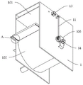
The invention provides a mechanical vibration type treatment device for treating marine aquaculture sewage, which specifically comprises: the top of the U-shaped shell is connected, a partition plate is fixedly arranged on the inner side of the top of the U-shaped shell, a transmission shaft, a driven shaft A and a driven shaft B are rotatably arranged between the partition plate and the U-shaped shell, and the transmission shaft is positioned in the middle of the driven shaft A and the driven shaft B; the bottom of the middle of the U-shaped shell is integrally provided with a U-shaped pool, and the bottom of the left side of the U-shaped pool penetrates through the U-shaped shell to be connected with a drain pipe; a sliding row is fixedly arranged below the left side of the U-shaped shell; the water discharge is fixedly arranged in the middle of the front side of the U-shaped shell, the front end of the water discharge is provided with a group of inlets, and the rear side of the water discharge is provided with a row of outlets; the central shaft is matched with the damping bearing and is rotatably arranged in the middle of the U-shaped shell, the center of the central shaft is aligned with the circle center of the U-shaped pool, and the driven shaft A, the driven shaft B and the central shaft are all self-locking shafts; a guide frame is fixedly arranged at the left side of the U-shaped shell; the rack frame is arranged in the guide frame in a sliding mode; the strip frame B is matched with the guide rail and is arranged at the top of the sliding row in a sliding mode, and a push-pull rod is fixedly arranged in the middle of the rear side of the strip frame B; the containing box is arranged in the middle of the rear side of the U-shaped shell in a sliding mode, and the rear end of the push-pull rod is fixedly connected with a connecting rod arranged on the left side of the containing box; the steering gear is rotationally arranged on the left side of the U-shaped shell, a rack part of the rack is positioned below the rear side and is meshed with the steering gear, and the number of teeth of the rack is half of that of the steering gear; an eccentric disc B is fixedly arranged at the left end of a rotating shaft of the steering gear, and an eccentric rod B is eccentrically and fixedly arranged at the left side of the eccentric disc B; the eccentric disc B is arranged in the strip-shaped frame B in a sliding manner; a motor cover is fixedly arranged on the front lower portion of the right side of the U-shaped shell, a motor B is fixedly arranged at the outer end of the motor cover, and a cross is fixedly arranged at the rotating shaft end of the motor B after penetrating through the motor cover.
Optionally, a transmission gear is fixedly arranged at the left end of the transmission shaft, and the transmission gear is a quarter gear; the right side of the U-shaped shell is provided with a motor A which is in transmission connection with the transmission shaft.
Optionally, a driven gear a is fixedly arranged at the left end of the driven shaft a; a driven gear B is fixedly arranged at the left end of the driven shaft B; the tooth number and tooth diameter of the driven gear A and the driven gear B are the same; the tooth surface tooth number of the transmission gear is half of that of the driven gear A and the driven gear B.
Optionally, the driven shaft B further includes: the left end of the eccentric disc A and the driven shaft B is fixedly provided with the eccentric disc A, and the left side of the eccentric disc A is eccentrically and fixedly provided with the eccentric rod A.
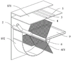
Optionally, the central shaft includes: the filter screen leaf, the fixed three filter screen leaves that are provided with in outside of center pin, three equidistant settings of filter screen leaves of group, and the inner wall in the marginal laminating U-shaped pond of filter screen leaf.
Optionally, the rack comprises: the rack is characterized by comprising a bar-shaped frame A, wherein the top of the rack frame is fixedly provided with the bar-shaped frame A; the eccentric rod A is arranged in the bar-shaped frame A in a sliding mode.
Optionally, the right side of the U-shaped shell is vertically and rotatably provided with a side shaft, the top end of the side shaft is in transmission connection with the driven shaft a through a bevel gear, and the bottom end of the side shaft is in transmission connection with the central shaft through a bevel gear.
Optionally, the driven shaft a rotates three times, and the central shaft rotates one time.
Optionally, the cross comprises: the sides of the cross are provided with four groups of hexagonal grooves; the pile driving device comprises a knocking pile, wherein a telescopic rod is fixedly arranged on one side of the knocking pile, a hexagonal block is fixedly arranged at one end of the telescopic rod, the hexagonal block is arranged in a hexagonal groove in a sliding mode, and a spring is fixedly arranged in the hexagonal groove; the knocking pile can contact the central shaft when rotating.
Advantageous effects
According to the transmission shaft, the driven shaft A and the driven shaft B of the invention, an intermittent transmission effect is provided, the transmission gear is a quarter gear, and the tooth surface number of the transmission gear is half of that of the driven gear A and the driven gear B, so that a mechanical differentiation structure can be formed, the original electric device control is replaced, the automatic segmented control is realized by using the accuracy reduction of mechanical transmission, and the error can be avoided.
In addition, motor B sets up alone, and it is rotatory to drive the cross through motor B, utilizes to strike a stake striking center pin and produces the vibration, conveys the vibration in the sewage via the conduction of filter screen leaf, and then carries out vibration treatment to sewage, prevents that sewage from condensing, can not influence the change of filter screen leaf, utilizes the vibration of filter screen leaf to provide and avoids sewage to condense and the adnexed dual effect of spot, can retrieve the filter.
In addition, strike the stake and provide the striking function, the fixed telescopic link that is provided with in one side of striking the stake, the fixed hexagonal piece that is provided with of one end of telescopic link, hexagonal piece slide to set up at hexagonal inslot, the fixed spring that is provided with in the hexagonal inslot, can contact the center pin when striking the stake rotation, provide the vibration effect to hexagonal piece can be through stress extrusion spring will strike the stake shrink, guarantees to strike the stake and can cross the center pin, accomplishes the vibrations that last.
Drawings
In order to more clearly illustrate the technical solutions of the embodiments of the present invention, the drawings of the embodiments will be briefly described below.
The drawings in the following description relate to some embodiments of the invention only and are not intended to limit the invention.
In the drawings:
FIG. 1 shows a schematic view of an overall three-dimensional structure according to an embodiment of the invention;
FIG. 2 illustrates a side-down perspective view according to an embodiment of the present invention;
FIG. 3 shows a perspective rear view schematic diagram according to an embodiment of the invention;
FIG. 4 shows a schematic side bottom view of an embodiment according to the invention;
FIG. 5 shows a disassembled perspective view of an embodiment of the present invention;
FIG. 6 shows a schematic perspective cross-sectional view of an embodiment according to the invention;
FIG. 7 shows a perspective view of a cross according to an embodiment of the invention;
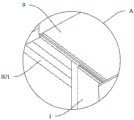
fig. 8 shows a partially enlarged schematic view of a in fig. 4 according to an embodiment of the invention.
List of reference numerals
1. A U-shaped shell; 101. a partition plate; 102. a U-shaped pool; 103. a drain pipe; 104. sliding the row; 105. a guide frame; 106. a motor cover; 2. water is discharged; 3. a drive shaft; 301. a transmission gear; 4. a driven shaft A; 401. a driven gear A; 5. a driven shaft B; 501. a driven gear B; 502. an eccentric disc A; 503. an eccentric rod A; 6. a central shaft; 601. a filter screen leaf; 7. a rack frame; 701. a bar frame A; 8. a bar frame B; 801. a push-pull rod; 9. a housing box; 10. a steering gear; 1001. an eccentric disc B; 1002. an eccentric rod B; 11. a side shaft; 12. a cross; 1201. a hexagonal groove; 1202. knocking the pile; 1203. a telescopic rod; 1204. hexagonal blocks; 13. a motor A; 14. and a motor B.
Detailed Description
In order to make the objects, aspects and advantages of the embodiments of the present invention more apparent, the embodiments of the present invention will be described in detail with reference to the accompanying drawings. Unless otherwise indicated, terms used herein have the ordinary meaning in the art. Like reference symbols in the various drawings indicate like elements.
Example (b): please refer to fig. 1 to 8:
the invention provides a mechanical vibration type treatment device for treating marine aquaculture sewage, which comprises: the top of the U-shaped shell 1 is connected with the top of the U-shaped shell 1, a partition plate 101 is fixedly arranged on the inner side of the top of the U-shaped shell 1, a transmission shaft 3, a driven shaft A4 and a driven shaft B5 are rotatably arranged between the partition plate 101 and the U-shaped shell 1, and the transmission shaft 3 is positioned in the middle of the driven shaft A4 and the driven shaft B5; the middle bottom of the U-shaped shell 1 is integrally provided with a U-shaped pool 102, and the left bottom of the U-shaped pool 102 penetrates through the U-shaped shell 1 and is connected with a drain pipe 103; a slide bar 104 is fixedly arranged below the left side of the U-shaped shell 1; the water discharge 2 is fixedly arranged in the middle of the front side of the U-shaped shell 1, the front end of the water discharge 2 is provided with a group of inlets, and the rear side of the water discharge 2 is provided with a row of outlets; the central shaft 6 is arranged in the middle of the U-shaped shell 1 in a rotating mode through matching with a damping bearing, the center of the central shaft 6 is aligned with the center of the U-shaped pool 102, and the driven shaft A4, the driven shaft B5 and the central shaft 6 are all self-locking shafts; a guide frame 105 is fixedly arranged at the left side of the U-shaped shell 1; a rack 7, wherein the rack 7 is arranged in the guide frame 105 in a sliding way; the strip-shaped frame B8 is arranged at the top of the sliding row 104 in a sliding manner by matching with a guide rail, and the middle of the rear side of the strip-shaped frame B8 is fixedly provided with a push-pull rod 801; the containing box 9 is arranged in the middle of the rear side of the U-shaped shell 1 in a sliding mode, the rear end of the push-pull rod 801 is fixedly connected with a connecting rod arranged on the left side of the containing box 9, the front side of the interior of the containing box 9 is higher than the rear side of the interior of the containing box 9, and a slope structure is formed; the steering gear 10 is rotationally arranged on the left side of the U-shaped shell 1, the rack part of the rack frame 7 is positioned below the rear side and meshed with the steering gear 10, and the number of teeth of the rack frame 7 is half of that of the steering gear 10; an eccentric disc B1001 is fixedly arranged at the left end of a rotating shaft of the steering gear 10, and an eccentric rod B1002 is eccentrically and fixedly arranged at the left side of the eccentric disc B1001; the eccentric disc B1001 is arranged in the strip-shaped frame B8 in a sliding manner; a motor cover 106 is fixedly arranged at the front lower part of the right side of the U-shaped shell 1, a motor B14 is fixedly arranged at the outer end of the motor cover 106, and a cross 12 is fixedly arranged at the rotating shaft end of the motor B14 through the motor cover 106.
Further, according to an embodiment of the present invention, referring to fig. 5 to 6, a transmission gear 301 is fixedly provided at a left end of the transmission shaft 3, and the transmission gear 301 is a quarter gear; the right side of the U-shaped shell 1 is provided with a motor A13 which is in transmission connection with a transmission shaft 3; a driven gear A401 is fixedly arranged at the left end of the driven shaft A4; a driven gear B501 is fixedly arranged at the left end of the driven shaft B5; the tooth diameters of the driven gear A401 and the driven gear B501 are the same; the tooth surface tooth number of the transmission gear 301 is half of that of the driven gear A401 and the driven gear B501, the transmission gear 301 can intermittently drive the driven gear A401 and the driven gear B501 to rotate in the rotating process, and the driven gear A401 and the driven gear B501 can intermittently rotate.
Further, according to an embodiment of the present invention, referring to fig. 5, the driven shaft B5 further includes: the eccentric disc A502, the left end of driven shaft B5 is fixed and is provided with eccentric disc A502, and the left side eccentric fixation of eccentric disc A502 is provided with eccentric rod A503, and the rack 7 is including: the top of the rack frame 7 is fixedly provided with a strip frame A701; the eccentric rod A503 is slidably disposed in the bar frame A701, and the eccentric disc A502 and the bar frame A701 constitute a reciprocating mechanism.
Further, according to an embodiment of the present invention, referring to fig. 5, the center shaft 6 includes: the filter screen blades 601 are fixedly provided with three groups of filter screen blades 601 outside the central shaft 6, the three groups of filter screen blades 601 are arranged at equal intervals, the edges of the filter screen blades 601 are attached to the inner wall of the U-shaped pool 102, and the bearing surfaces of the filter screen blades 601 are provided with blocking strip structures.
In addition, according to the embodiment of the invention, the side shaft 11 is vertically and rotatably arranged on the right side of the U-shaped shell 1, the top end of the side shaft 11 is in bevel gear transmission connection with the driven shaft A4, the bottom end of the side shaft 11 is in bevel gear transmission connection with the central shaft 6, and the central shaft 6 rotates for one circle when the driven shaft A4 rotates for three circles, so that the mechanical motion period differentiation is realized, and errors caused by electrical control cannot occur.
Further, according to an embodiment of the present invention, referring to fig. 7, the cross 12 includes: the six-sided groove 1201, the side of the cross 12 has four groups of six-sided grooves 1201; the pile driving device comprises a knocking pile 1202, wherein a telescopic rod 1203 is fixedly arranged on one side of the knocking pile 1202, a hexagonal block 1204 is fixedly arranged at one end of the telescopic rod 1203, the hexagonal block 1204 is arranged in a hexagonal groove 1201 in a sliding mode, and a spring is fixedly arranged in the hexagonal groove 1201; the driven stub 1202 is able to contact the central shaft 6 when rotated, providing a vibratory effect.
The specific use mode and function of the embodiment are as follows: in the present invention, when in use, the sewage connecting water 2 is divided and transported, sprinkled on the top of the front filter screen blade 601, filtered by the filter screen blade 601, flows into the U-shaped tank 102, and discharged from the drain pipe 103.
Motor B14 and motor A13 synchronous start, motor B14 drive cross 12 rotatory, utilize to strike stake 1202 and strike center pin 6 and produce the vibration, convey the vibration in the sewage via the conduction of filter screen leaf 601, and then carry out vibration treatment to sewage, prevent that sewage from condensing.
The motor A13 drives the transmission shaft 3 to rotate, the transmission shaft 3 drives the transmission gear 301 to rotate, the transmission gear 301 firstly drives the driven shaft B5, the driven gear B501 and the eccentric disc A502 to rotate for half a circle, the rack frame 7 and the strip frame A701 are moved downwards by the eccentric rod A503, the eccentric disc B1001 and the eccentric rod B1002 are driven to rotate for half a circle by matching with the steering gear 10, the strip frame B8, the push-pull rod 801 and the containing box 9 are moved backwards, the containing box 9 is pulled out, the driven shaft A4 and the driven gear A401 are driven to rotate for half a circle, meanwhile, the side shaft 11 drives the central shaft 6 to rotate for half a circle, the central shaft 6 and the filter screen leaves 601 are rotated for 60 degrees, at the moment, the containing box 9 is higher than the filter screen leaves 601 at the rear side, then the driven shaft B5, the driven gear B501 and the eccentric disc A502 are rotated for half a circle, the containing box 9 is reset, the central shaft 6 and the filter screen leaves 601 are rotated for 60 degrees, filtered impurities fall into the containing box 9, and recovery is completed, meanwhile, the filter screen blade 601 is replaced, and impurities are prevented from being attached to the outer surface of the filter screen blade 601 through vibration.
Finally, it should be noted that, when describing the positions of the components and the matching relationship therebetween, the present invention is usually illustrated by one/a pair of components, however, it should be understood by those skilled in the art that such positions, matching relationship, etc. are also applicable to other/other pairs of components.
The above description is intended to be illustrative of the present invention and not to limit the scope of the invention, which is defined by the claims appended hereto.
Claims (3)
1. A mechanical vibration type treatment equipment for treating marine aquaculture sewage, which is characterized by comprising: the transmission shaft is characterized by comprising a U-shaped shell (1), the top of the U-shaped shell (1) is connected, a partition plate (101) is fixedly arranged on the inner side of the top of the U-shaped shell (1), a transmission shaft (3), a driven shaft A (4) and a driven shaft B (5) are rotatably arranged between the partition plate (101) and the U-shaped shell (1), and the transmission shaft (3) is located in the middle of the driven shaft A (4) and the driven shaft B (5);
the middle bottom of the U-shaped shell (1) is integrally provided with a U-shaped pool (102), and the left bottom of the U-shaped pool (102) penetrates through the U-shaped shell (1) to be connected with a drain pipe (103); a slide bar (104) is fixedly arranged below the left side of the U-shaped shell (1);
the water discharge device comprises a water discharge device (2), wherein the water discharge device (2) is fixedly arranged in the middle of the front side of a U-shaped shell (1), the front end of the water discharge device (2) is provided with a group of inlets, and the rear side of the water discharge device (2) is provided with a row of outlets; the central shaft (6) is matched with the damping bearing and is rotatably arranged in the middle of the U-shaped shell (1), the central shaft (6) is aligned with the circle center of the U-shaped pool (102), and the driven shaft A (4), the driven shaft B (5) and the central shaft (6) are self-locking shafts; a guide frame (105) is fixedly arranged at the left side of the U-shaped shell (1); the rack frame (7), the rack frame (7) is arranged in the guide frame (105) in a sliding mode;
the strip-shaped frame B (8) is matched with the guide rail and is arranged at the top of the sliding row (104) in a sliding mode, and a push-pull rod (801) is fixedly arranged in the middle of the rear side of the strip-shaped frame B (8); the containing box (9) is arranged in the middle of the rear side of the U-shaped shell (1) in a sliding mode, and the rear end of the push-pull rod (801) is fixedly connected with a connecting rod arranged on the left side of the containing box (9); the steering gear (10) is rotationally arranged on the left side of the U-shaped shell (1), the rack part of the rack (7) is positioned below the rear side and meshed with the steering gear (10), and the number of teeth of the rack (7) is half of that of the steering gear (10); an eccentric disc B (1001) is fixedly arranged at the left end of a rotating shaft of the steering gear (10), and an eccentric rod B (1002) is eccentrically and fixedly arranged at the left side of the eccentric disc B (1001); the eccentric disc B (1001) is arranged in the bar-shaped frame B (8) in a sliding manner; a motor cover (106) is fixedly arranged at the front lower part of the right side of the U-shaped shell (1), a motor B (14) is fixedly arranged at the outer end of the motor cover (106), and a cross (12) is fixedly arranged at the rotating shaft end of the motor B (14) through the motor cover (106);
a transmission gear (301) is fixedly arranged at the left end of the transmission shaft (3), and the transmission gear (301) is a quarter gear; the right side of the U-shaped shell (1) is provided with a motor A (13) which is in transmission connection with the transmission shaft (3);
a driven gear A (401) is fixedly arranged at the left end of the driven shaft A (4); a driven gear B (501) is fixedly arranged at the left end of the driven shaft B (5); the tooth diameters of the driven gear A (401) and the driven gear B (501) are the same; the tooth surface tooth number of the transmission gear (301) is half of that of the driven gear A (401) and the driven gear B (501);
the driven shaft B (5) further comprises: the left side of the eccentric disc A (502) and the driven shaft B (5) is fixedly provided with the eccentric disc A (502), and the left side of the eccentric disc A (502) is eccentrically and fixedly provided with an eccentric rod A (503);
the central shaft (6) comprises: the filter screen blades (601), three groups of filter screen blades (601) are fixedly arranged outside the central shaft (6), the three groups of filter screen blades (601) are arranged at equal intervals, and the edges of the filter screen blades (601) are attached to the inner wall of the U-shaped pool (102);
the rack (7) comprises: the rack is characterized by comprising a bar-shaped frame A (701), wherein the top of the rack frame (7) is fixedly provided with the bar-shaped frame A (701); the eccentric rod A (503) is arranged in the bar-shaped frame A (701) in a sliding manner;
a side shaft (11) is vertically and rotatably arranged on the right side of the U-shaped shell (1), the top end of the side shaft (11) is in transmission connection with a driven shaft A (4) through a bevel gear, and the bottom end of the side shaft (11) is in transmission connection with a central shaft (6) through the bevel gear.
2. A mechanically vibrating treatment device for treatment of marine aquaculture sewage according to claim 1 wherein the driven shaft a (4) rotates three revolutions while the central shaft (6) rotates one revolution.
3. A mechanically vibrating treatment apparatus for treatment of marine aquaculture wastewater according to claim 1 wherein said cross (12) comprises:
the device comprises a hexagonal groove (1201), wherein four groups of hexagonal grooves (1201) are formed in the side of a cross (12);
the device comprises a knocking pile (1202), wherein a telescopic rod (1203) is fixedly arranged on one side of the knocking pile (1202), a hexagonal block (1204) is fixedly arranged at one end of the telescopic rod (1203), the hexagonal block (1204) is arranged in a hexagonal groove (1201) in a sliding mode, and a spring is fixedly arranged in the hexagonal groove (1201); the knocking pile (1202) can contact the central shaft (6) when rotating.
Priority Applications (1)
| Application Number | Priority Date | Filing Date | Title |
|---|---|---|---|
| CN202210082368.1A CN114105251B (en) | 2022-01-25 | 2022-01-25 | Mechanical vibration type treatment equipment for treating marine aquaculture sewage |
Applications Claiming Priority (1)
| Application Number | Priority Date | Filing Date | Title |
|---|---|---|---|
| CN202210082368.1A CN114105251B (en) | 2022-01-25 | 2022-01-25 | Mechanical vibration type treatment equipment for treating marine aquaculture sewage |
Publications (2)
| Publication Number | Publication Date |
|---|---|
| CN114105251A CN114105251A (en) | 2022-03-01 |
| CN114105251B true CN114105251B (en) | 2022-04-15 |
Family
ID=80361267
Family Applications (1)
| Application Number | Title | Priority Date | Filing Date |
|---|---|---|---|
| CN202210082368.1A Expired - Fee Related CN114105251B (en) | 2022-01-25 | 2022-01-25 | Mechanical vibration type treatment equipment for treating marine aquaculture sewage |
Country Status (1)
| Country | Link |
|---|---|
| CN (1) | CN114105251B (en) |
Families Citing this family (1)
| Publication number | Priority date | Publication date | Assignee | Title |
|---|---|---|---|---|
| CN116510391A (en) * | 2023-06-28 | 2023-08-01 | 山东省海洋资源与环境研究院(山东省海洋环境监测中心、山东省水产品质量检验中心) | Mechanical vibration type treatment equipment for treating marine aquaculture sewage |
Citations (3)
| Publication number | Priority date | Publication date | Assignee | Title |
|---|---|---|---|---|
| CN205031958U (en) * | 2015-08-25 | 2016-02-17 | 东莞安默琳机械制造技术有限公司 | Rotary drum type filter |
| CN111549737A (en) * | 2020-05-11 | 2020-08-18 | 黄明明 | Water quality primary treatment equipment for river channel |
| CN215310521U (en) * | 2021-07-29 | 2021-12-28 | 广东岱正科技有限公司 | Waste sulfuric acid recycling device for aluminum sulfate solid water purifying agent production |
Family Cites Families (6)
| Publication number | Priority date | Publication date | Assignee | Title |
|---|---|---|---|---|
| EP0463195B1 (en) * | 1990-06-23 | 1993-12-15 | Ralf F. Piepho Abwassertechnik GmbH | Movable device for the purification of all kinds of sewage |
| CN109157892B (en) * | 2018-08-30 | 2020-10-20 | 江苏欧仕达润滑油有限公司 | Movable liquid pool slag removal and filtration equipment |
| CN111593787B (en) * | 2020-05-25 | 2021-05-25 | 绍兴玖越智能装备有限公司 | Rainwater collecting device |
| WO2022178883A1 (en) * | 2021-02-27 | 2022-09-01 | 苏州赛荣建筑装饰工程有限公司 | Underground leachate sewage treatment equipment |
| CN113249908B (en) * | 2021-07-16 | 2021-09-14 | 江苏盈彩纺织科技有限公司 | Textile fabric conveying device based on intermittent tensioning and vibration drainage drying structure |
| CN113737877B (en) * | 2021-09-27 | 2023-05-05 | 新疆中核二一六建设有限公司 | Farmland ditch dredging equipment capable of supplementing water level based on hydraulic engineering |
-
2022
- 2022-01-25 CN CN202210082368.1A patent/CN114105251B/en not_active Expired - Fee Related
Patent Citations (3)
| Publication number | Priority date | Publication date | Assignee | Title |
|---|---|---|---|---|
| CN205031958U (en) * | 2015-08-25 | 2016-02-17 | 东莞安默琳机械制造技术有限公司 | Rotary drum type filter |
| CN111549737A (en) * | 2020-05-11 | 2020-08-18 | 黄明明 | Water quality primary treatment equipment for river channel |
| CN215310521U (en) * | 2021-07-29 | 2021-12-28 | 广东岱正科技有限公司 | Waste sulfuric acid recycling device for aluminum sulfate solid water purifying agent production |
Also Published As
| Publication number | Publication date |
|---|---|
| CN114105251A (en) | 2022-03-01 |
Similar Documents
| Publication | Publication Date | Title |
|---|---|---|
| EP1841312B1 (en) | Filtering device, in particular for a fish basin | |
| CN114105251B (en) | Mechanical vibration type treatment equipment for treating marine aquaculture sewage | |
| CN109912063A (en) | A kind of energy saving and environment friendly effluent treatment plant | |
| CN210145583U (en) | Environment-friendly impurity removing device for engineering sewage treatment | |
| CN117088564A (en) | Agricultural vegetable wastewater treatment system and treatment method | |
| CN216358837U (en) | Metal filters with prevent blockking up structure | |
| CN216890853U (en) | Tobacco essence processing and extracting equipment | |
| CN216629945U (en) | Solid-liquid separation device for mucosa extract | |
| CN113248042B (en) | Distributed domestic sewage high-efficiency nitrogen and phosphorus removal treatment system and treatment process thereof | |
| CN215905978U (en) | Sewage treatment device | |
| CN114681986A (en) | Sewage filtering treatment system | |
| CN210613016U (en) | Sewage filtering device | |
| CN114516688A (en) | Fluorine chemical industry production wastewater treatment equipment | |
| CN112499823A (en) | Sewage treatment plant is used in bridge construction | |
| CN219290754U (en) | Quick biochemical sewage purification equipment | |
| CN112499793A (en) | Sedimentation type sewage purification system and purification method thereof | |
| CN220237901U (en) | Wastewater treatment device with anti-blocking structure | |
| CN219341869U (en) | Water purifier capable of collecting impurities | |
| KR101602769B1 (en) | Dehydrator with movable multi-disc | |
| CN217367339U (en) | Sewage treatment purifier for municipal administration blowdown | |
| CN220609267U (en) | Filter with on-line brine monitoring | |
| CN218322601U (en) | Waterproof drainage device of hydraulic engineering construction | |
| CN218485295U (en) | Waste water classification filter equipment | |
| CN219209209U (en) | Anti-blocking sewage filtering device | |
| CN219596117U (en) | Sewage treatment collecting tank |
Legal Events
| Date | Code | Title | Description |
|---|---|---|---|
| PB01 | Publication | ||
| PB01 | Publication | ||
| SE01 | Entry into force of request for substantive examination | ||
| SE01 | Entry into force of request for substantive examination | ||
| GR01 | Patent grant | ||
| GR01 | Patent grant | ||
| CF01 | Termination of patent right due to non-payment of annual fee | ||
| CF01 | Termination of patent right due to non-payment of annual fee |
Granted publication date: 20220415 |